1994 JEEP CHEROKEE coolant temperature
[x] Cancel search: coolant temperaturePage 862 of 1784

(5) Place the engine cylinder head over the dowels.
CAUTION: Engine cylinder head bolts should be re-
used only once. Replace the head bolts if they were
used before or if they have a paint dab on the top
of the bolt.
(6) Coat the threads of bolt No.7, only, with Loctite
PST sealant or equivalent.
(7) Install all head bolts, except No.8 and No.10.
(8) Remove the dowels.
(9) Install No.8 and No.10 head bolts.
(10) Tighten the engine cylinder head bolts in se-
quence according to the following procedure (Fig. 6):
(a) Tighten all bolts in sequence (1 through 10)
to 30 Nzm (22 ft. lbs.) torque.
(b) Tighten all bolts in sequence (1 through 10)
to 61 Nzm (45 ft. lbs.) torque.
(c) Check all bolts to verify they are set to 61
Nzm (45 ft. lbs.) torque.
(d) Tighten bolts (in sequence):
²Bolts 1 through 6 to 149 Nzm (110 ft. lbs.) torque.
²Bolt 7 to 136 Nzm (100 ft. lbs.) torque.
²Bolts 8 through 10 to 149 Nzm (110 ft. lbs.) torque.
CAUTION: During the final tightening sequence,
bolt No.7 will be tightened to a lower torque than
the rest of the bolts. DO NOT overtighten bolt No.7.
(e) Check all bolts in sequence to verify the cor-
rect torque.
(f) If not already done, clean and mark each bolt
with a dab of paint after tightening. Should you
encounter bolts which were painted in an earlier
service operation, replace them.
(11) Install the ignition coil and bracket assembly.
(12) Connect the temperature sending unit wire
connector.
(13) Install the spark plugs and tighten to 37 Nzm
(27 ft. lbs.) torque. Connect the ignition wires.(14) Install the intake and exhaust manifolds (re-
fer to Group 11, Exhaust System and Intake Mani-
fold for the proper procedures).
(15) Install the fuel lines and the vacuum advance
hose.
(16) If equipped, attach the power steering pump
and bracket.
(17) Install the push rods, rocker arms, pivots and
bridges in the order they were removed.
(18) Install the engine cylinder head cover.
(19) Attach the air conditioning compressor mount-
ing bracket to the engine cylinder head and block.
Tighten the bolts to 40 Nzm (30 ft. lbs.) torque.
(20) Attach the air conditioning compressor to the
bracket. Tighten the bolts to 27 Nzm (20 ft. lbs.)
torque.
CAUTION: The serpentine drive belt must be routed
correctly. Incorrect routing can cause the water
pump to turn in the opposite direction causing the
engine to overheat.
(21) Install the serpentine drive belt and correctly
tension the belt (refer to Group 7, Cooling System for
the proper procedure).
(22) Install the air cleaner and ducting.
(23) Install the engine cylinder head cover.
(24) Connect the hoses to the thermostat housing
and fill the cooling system to the specified level (re-
fer to Group 7, Cooling Systems for the proper proce-
dure).
(25) The automatic transmission throttle linkage
and cable must be adjusted after completing the en-
gine cylinder head installation (refer to Group 21,
Transmissions for the proper procedures).
(26) Install the temperature sending unit and con-
nect the wire connector.
(27) Connect the fuel pipe and vacuum advance
hose.
(28) Connect negative cable to battery.
(29) Connect the upper radiator hose and heater
hose at the thermostat housing.
(30) Fill the cooling system. Check for leaks.
WARNING: USE EXTREME CAUTION WHEN THE
ENGINE IS OPERATING. DO NOT STAND IN DIRECT
LINE WITH THE FAN. DO NOT PUT HANDS NEAR
THE PULLEYS, BELTS OR FAN. DO NOT WEAR
LOOSE CLOTHING.
(31) Operate the engine with the radiator cap off.
Inspect for leaks and continue operating the engine
until the thermostat opens. Add coolant, if required.
VALVE SPRINGS AND OIL SEALS
This procedure can be done with the engine cylin-
der head installed on the block.
Fig. 6 Engine cylinder head Bolt Tightening
Sequence
J2.5L ENGINE 9 - 21
Page 900 of 1784
(17) Tighten the serpentine drive belt according to
the specifications listed in Group 7, Cooling System.
(18) Install the fan shroud and radiator (refer to
Group 7, Cooling System for the proper procedure).
(19) Connect the radiator hoses.
(20) Connect the throttle valve rod and retainer.
(21) Connect the throttle cable and install the rod.
(22) Install the throttle valve rod spring.
(23) Connect the speed control cable, if equipped.
(24) Connect the oxygen sensor wire connector.
(25) Install the vacuum hose and check valve on
the brake booster.
(26) Connect the coolant temperature sensor wire
connector.
(27) Connect the idle speed actuator wire connec-
tor.
(28) Connect the fuel inlet and return hoses at the
fuel rail. Verify that the quick-connect fitting assem-
bly fits securely over the fuel lines by giving the fuel
lines a firm tug.
(29) Install the fuel line bracket to the intake
manifold.
(30) Connect all fuel injection wire connections.
(31) Install the engine ground strap.
(32) Connect the ignition coil wire connector.
(33) Remove the coolant temperature sending unit
to permit air to escape from the block. Fill the cool-
ing system with coolant. Install the coolant tempera-
ture sending unit when the system is filled.
(34) If equipped with power steering:
(a) Remove the protective caps
(b) Connect the hoses to the fittings at the steer-
ing gear. Tighten the nut to 52 Nzm (38 ft. lbs.)
torque.
(c) Fill the pump reservoir with fluid.
(35) Install the battery and connect the battery ca-
bles.
(36) Install the air cleaner bonnet to the throttle
body.
(37) Install the air cleaner.
(38) Lower the hood and secure in place.
(39) Start the engine and inspect for leaks.
(40) Stop the engine and check the fluid levels.
Add fluid, as required.
ENGINE CYLINDER HEAD COVER
A cured gasket is part of the engine cylinder head
cover.
REMOVAL
(1) Disconnect negative cable from battery.
(2) Disconnect the Crankcase Ventilation (CCV)
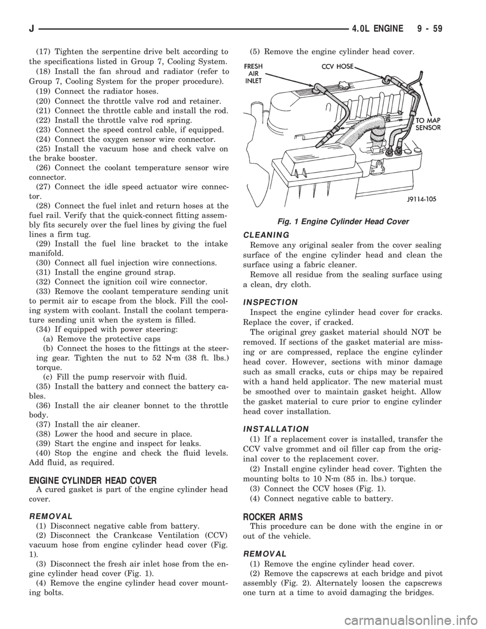
vacuum hose from engine cylinder head cover (Fig.
1).
(3) Disconnect the fresh air inlet hose from the en-
gine cylinder head cover (Fig. 1).
(4) Remove the engine cylinder head cover mount-
ing bolts.(5) Remove the engine cylinder head cover.
CLEANING
Remove any original sealer from the cover sealing
surface of the engine cylinder head and clean the
surface using a fabric cleaner.
Remove all residue from the sealing surface using
a clean, dry cloth.
INSPECTION
Inspect the engine cylinder head cover for cracks.
Replace the cover, if cracked.
The original grey gasket material should NOT be
removed. If sections of the gasket material are miss-
ing or are compressed, replace the engine cylinder
head cover. However, sections with minor damage
such as small cracks, cuts or chips may be repaired
with a hand held applicator. The new material must
be smoothed over to maintain gasket height. Allow
the gasket material to cure prior to engine cylinder
head cover installation.
INSTALLATION
(1) If a replacement cover is installed, transfer the
CCV valve grommet and oil filler cap from the orig-
inal cover to the replacement cover.
(2) Install engine cylinder head cover. Tighten the
mounting bolts to 10 Nzm (85 in. lbs.) torque.
(3) Connect the CCV hoses (Fig. 1).
(4) Connect negative cable to battery.
ROCKER ARMS
This procedure can be done with the engine in or
out of the vehicle.
REMOVAL
(1) Remove the engine cylinder head cover.
(2) Remove the capscrews at each bridge and pivot
assembly (Fig. 2). Alternately loosen the capscrews
one turn at a time to avoid damaging the bridges.
Fig. 1 Engine Cylinder Head Cover
J4.0L ENGINE 9 - 59
Page 902 of 1784

(11) Remove the intake and engine exhaust mani-
folds from the engine cylinder head (refer to Group
11, Exhaust System and Intake Manifold for the
proper procedures).
(12) Disconnect the ignition wires and remove the
spark plugs.
(13) Disconnect the temperature sending unit wire
connector.
(14) Remove the ignition coil and bracket assem-
bly.
(15) Remove the engine cylinder head bolts. Bolt
No.14 cannot be removed until the head is moved
forward (Fig. 3). Pull bolt No.14 out as far as it will
go and then suspend the bolt in this position (tape
around the bolt).
(16) Remove the engine cylinder head and gasket
(Fig. 3).
(17) If this was the first time the bolts were re-
moved, put a paint dab on the top of the bolt. If the
bolts have a paint dab on the top of the bolt or it
isn't known if they were used before, discard the
bolts.
(18) Stuff clean lint free shop towels into the cyl-
inder bores.
CLEANING
Thoroughly clean the engine cylinder head and cyl-
inder block mating surfaces. Clean the intake and
engine exhaust manifold and engine cylinder head
mating surfaces. Remove all gasket material and car-
bon.
Check to ensure that no coolant or foreign material
has fallen into the tappet bore area.
Remove the carbon deposits from the combustion
chambers and top of the pistons.
INSPECTION
Use a straightedge and feeler gauge to check the
flatness of the engine cylinder head and block mat-
ing surfaces.
INSTALLATION
The engine cylinder head gasket is a composition
gasket. The gasket is to be installed DRY.DO NOT
use a gasket sealing compound on the gasket.
If the engine cylinder head is to be replaced and
the original valves used, measure the valve stem di-
ameter. Only standard size valves can be used with a
service replacement engine cylinder head unless the
replacement head valve stem guide bores are reamed
to accommodate oversize valve stems. Remove all
carbon buildup and reface the valves.
(1) Remove the shop towels from the cylinder
bores. Coat the bores with clean engine oil.
(2) Position the engine cylinder head gasket (with
the numbers facing up) onto the cylinder block.
CAUTION: Engine cylinder head bolts should be re-
used only once. Replace the head bolts if they were
used before or if they have a paint dab on the top
of the bolt.
(3) With bolt No.14 held in place (tape around
bolt), install the engine cylinder head. Remove the
tape from bolt No.14.
(4) Coat the threads of stud bolt No.11 with Loctite
592 sealant, or equivalent.
(5) Tighten the engine cylinder head bolts in se-
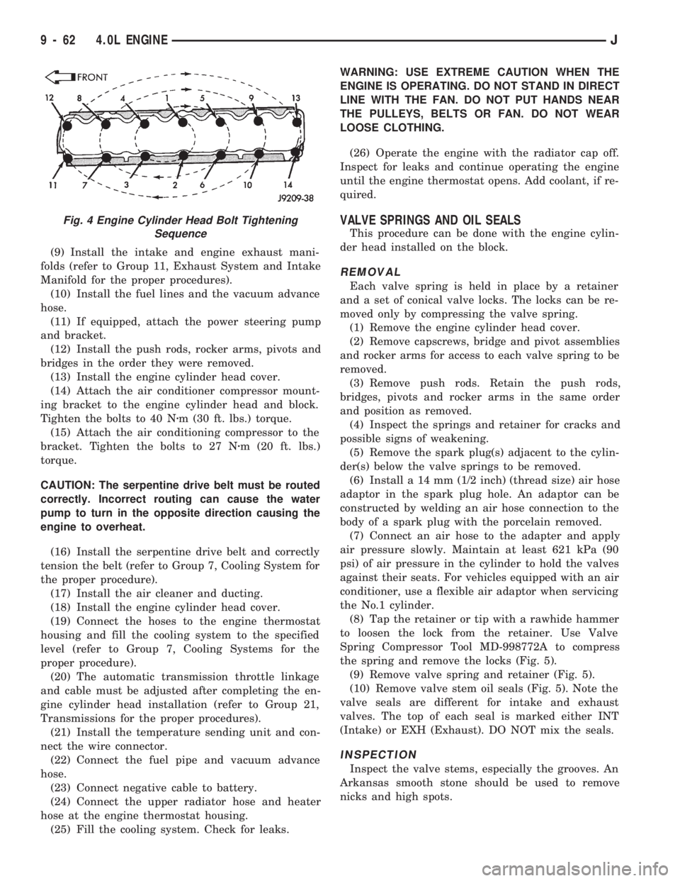
quence according to the following procedure (Fig. 4):
(a) Tighten all bolts in sequence (1 through 14)
to 30 Nzm (22 ft. lbs.) torque.
(b) Tighten all bolts in sequence (1 through 14)
to 61 Nzm (45 ft. lbs.) torque.
(c) Check all bolts to verify they are set to 61
Nzm (45 ft. lbs.) torque.
(d) Tighten bolts (in sequence):
²Bolts 1 through 10 to 149 Nzm (110 ft. lbs.) torque.
²Bolt 11 to 136 Nzm (100 ft. lbs.) torque.
²Bolts 12 through 14 to 149 Nzm (110 ft. lbs.)
torque.
CAUTION: During the final tightening sequence,
bolt No.11 will be tightened to a lower torque than
the rest of the bolts. DO NOT overtighten bolt
No.11.
(e) Check all bolts in sequence to verify the cor-
rect torque.
(f) If not already done, clean and mark each bolt
with a dab of paint after tightening. Should you
encounter bolts which were painted in an earlier
service operation, replace them.
(6) Install the ignition coil and bracket assembly.
(7) Connect the temperature sending unit wire
connector.
(8) Install the spark plugs and tighten to 37 Nzm
(27 ft. lbs.) torque. Connect the ignition wires.
Fig. 3 Engine Cylinder Head Assembly
J4.0L ENGINE 9 - 61
Page 903 of 1784
(9) Install the intake and engine exhaust mani-
folds (refer to Group 11, Exhaust System and Intake
Manifold for the proper procedures).
(10) Install the fuel lines and the vacuum advance
hose.
(11) If equipped, attach the power steering pump
and bracket.
(12) Install the push rods, rocker arms, pivots and
bridges in the order they were removed.
(13) Install the engine cylinder head cover.
(14) Attach the air conditioner compressor mount-
ing bracket to the engine cylinder head and block.
Tighten the bolts to 40 Nzm (30 ft. lbs.) torque.
(15) Attach the air conditioning compressor to the
bracket. Tighten the bolts to 27 Nzm (20 ft. lbs.)
torque.
CAUTION: The serpentine drive belt must be routed
correctly. Incorrect routing can cause the water
pump to turn in the opposite direction causing the
engine to overheat.
(16) Install the serpentine drive belt and correctly
tension the belt (refer to Group 7, Cooling System for
the proper procedure).
(17) Install the air cleaner and ducting.
(18) Install the engine cylinder head cover.
(19) Connect the hoses to the engine thermostat
housing and fill the cooling system to the specified
level (refer to Group 7, Cooling Systems for the
proper procedure).
(20) The automatic transmission throttle linkage
and cable must be adjusted after completing the en-
gine cylinder head installation (refer to Group 21,
Transmissions for the proper procedures).
(21) Install the temperature sending unit and con-
nect the wire connector.
(22) Connect the fuel pipe and vacuum advance
hose.
(23) Connect negative cable to battery.
(24) Connect the upper radiator hose and heater
hose at the engine thermostat housing.
(25) Fill the cooling system. Check for leaks.WARNING: USE EXTREME CAUTION WHEN THE
ENGINE IS OPERATING. DO NOT STAND IN DIRECT
LINE WITH THE FAN. DO NOT PUT HANDS NEAR
THE PULLEYS, BELTS OR FAN. DO NOT WEAR
LOOSE CLOTHING.
(26) Operate the engine with the radiator cap off.
Inspect for leaks and continue operating the engine
until the engine thermostat opens. Add coolant, if re-
quired.
VALVE SPRINGS AND OIL SEALS
This procedure can be done with the engine cylin-
der head installed on the block.
REMOVAL
Each valve spring is held in place by a retainer
and a set of conical valve locks. The locks can be re-
moved only by compressing the valve spring.
(1) Remove the engine cylinder head cover.
(2) Remove capscrews, bridge and pivot assemblies
and rocker arms for access to each valve spring to be
removed.
(3) Remove push rods. Retain the push rods,
bridges, pivots and rocker arms in the same order
and position as removed.
(4) Inspect the springs and retainer for cracks and
possible signs of weakening.
(5) Remove the spark plug(s) adjacent to the cylin-
der(s) below the valve springs to be removed.
(6) Install a 14 mm (1/2 inch) (thread size) air hose
adaptor in the spark plug hole. An adaptor can be
constructed by welding an air hose connection to the
body of a spark plug with the porcelain removed.
(7) Connect an air hose to the adapter and apply
air pressure slowly. Maintain at least 621 kPa (90
psi) of air pressure in the cylinder to hold the valves
against their seats. For vehicles equipped with an air
conditioner, use a flexible air adaptor when servicing
the No.1 cylinder.
(8) Tap the retainer or tip with a rawhide hammer
to loosen the lock from the retainer. Use Valve
Spring Compressor Tool MD-998772A to compress
the spring and remove the locks (Fig. 5).
(9) Remove valve spring and retainer (Fig. 5).
(10) Remove valve stem oil seals (Fig. 5). Note the
valve seals are different for intake and exhaust
valves. The top of each seal is marked either INT
(Intake) or EXH (Exhaust). DO NOT mix the seals.
INSPECTION
Inspect the valve stems, especially the grooves. An
Arkansas smooth stone should be used to remove
nicks and high spots.
Fig. 4 Engine Cylinder Head Bolt Tightening
Sequence
9 - 62 4.0L ENGINEJ
Page 939 of 1784
INTAKE MANIFOLDÐ2.5L ENGINE
REMOVAL
(1) Disconnect the battery negative cable.
(2) Remove the air inlet hose from the throttle
body and air cleaner.
(3) Loosen the accessory drive belt tension and re-
move the belt from the power steering pump.
(4) Remove the power steering pump and brackets
from the water pump and intake manifold. Support
power steering pump and bracket with mechanics
wire attached to the radiator upper crossmember.
(5) Remove the fuel tank filler cap to relieve the
fuel tank pressure.
(6) Install the fuel tank filler cap.
(7) Disconnect fuel supply and return tube from
the fuel rail (refer to Group 14, Fuel System - Quick
Connect Fittings).
(8) Disconnect the accelerator cable from the throt-
tle body and the holddown bracket.
CAUTION: When disconnecting the cruise control
connector at the throttle body, DO NOT pry the con-
nector off with pliers or screwdriver. Use finger
pressure only. Prying the connector off could break
it.
(9) Disconnect the electrical connectors. Pull the
harnesses away from the manifold.
²The throttle position sensor.
²The idle speed control motor.
²The coolant temperature sensor at the thermostat.
²The manifold air temperature sensor at the intake
manifold.
²The fuel injectors.
²The oxygen sensor.
(10) Disconnect the crankcase ventilation (CCV)
vacuum hose and manifold absolute pressure (MAP)
sensor vacuum hose connector at the intake mani-
fold.
(11) Disconnect vacuum hose from vacuum port on
the intake manifold.
(12) Disconnect CCV hose at the cylinder head
cover (Fig. 12).
(13) Remove the molded vacuum harness.
(14) Disconnect the vacuum brake booster hose at
the intake manifold.
(15) Remove bolts 2 through 5 securing the intake
manifold to the cylinder head (Fig. 11). Slightly
loosen bolt No.1 and nuts 6 and 7.
(16) Remove the intake manifold and gaskets.
Drain the coolant from the manifold.
CLEANING
Clean the intake manifold and cylinder head mat-
ing surfaces.DO NOT allow foreign material to
enter either the intake manifold or the ports in
the cylinder head.
INSTALLATION
(1) Install the new intake manifold gasket over the
locating dowels.
(2) Position the manifold in place and finger
tighten the mounting bolts.
(3) Tighten the fasteners in sequence and to the
specified torque (Fig. 11).
²Fastener No.1ÐTighten to 41 Nzm (30 ft. lbs.)
torque.
²Fasteners Nos.2 through 7ÐTighten to 31 Nzm (23
ft. lbs.) torque.
(4) Connect the fuel return and supply tube to the
connector next to the fuel rail. Push them into the
fitting until a click is heard. Verify that the connec-
tions are complete.
²First, ensure only the retainer tabs protrude from
the connectors.
²Second, pull out on the fuel tubes to ensure they
are locked in place.
(5) Connect the molded vacuum hoses to the vac-
uum port on the intake manifold and the cylinder
head cover.
(6) Connect the electrical connectors.
²The throttle position sensor.
²The automatic idle speed control motor.
²The coolant temperature sensor at the thermostat
housing.
²The fuel injectors.
²The air manifold temperature sensor.
²The oxygen sensor.
(7) Connect the CCV vacuum hose and MAP sen-
sor vacuum hose connectors to the throttle body.
(8) Install the power steering pump and bracket
assembly to the water pump and intake manifold.
(9) Connect the accelerator cable and cruise control
cable to the holddown bracket and the throttle arm.
Fig. 12 Crankcase Ventilation (CCV) Hose
(2.5L Engine)
11 - 8 EXHAUST SYSTEM AND INTAKE MANIFOLDJ
Page 978 of 1784
MULTI-PORT FUEL INJECTION (MFI)ÐCOMPONENT DESCRIPTION/SYSTEM
OPERATION
INDEX
page page
Air Conditioning (A/C) Clutch RelayÐPCM Output.24
Air Conditioning (A/C) ControlsÐPCM Input.... 19
Auto Shut Down (ASD) RelayÐPCM Output.... 24
Automatic Shut Down (ASD) SenseÐPCM Input . 19
Battery VoltageÐPCM Input................ 19
Brake SwitchÐPCM Input.................. 20
Camshaft Position SensorÐPCM Input........ 20
Crankshaft Position SensorÐPCM Input....... 20
Data Link ConnectorÐPCM Input............ 20
Data Link ConnectorÐPCM Output........... 24
EMR LampÐPCM Output.................. 24
Engine Coolant Temperature SensorÐPCM Input . 21
Extended Idle SwitchÐPCM Input............ 21
Fuel InjectorsÐPCM Output................ 25
Fuel Pressure Regulator................... 30
Fuel Pump RelayÐPCM Output............. 25
Fuel Rail............................... 30
General Information....................... 17
Generator FieldÐPCM Output............... 25
Generator LampÐPCM Output.............. 25
Idle Air Control (IAC) MotorÐPCM Output...... 25
Ignition Circuit SenseÐPCM Input............ 21
Ignition CoilÐPCM Output.................. 26Intake Air Temperature SensorÐPCM Input.... 20
Malfunction Indicator LampÐPCM Output...... 26
Manifold Absolute Pressure (MAP) SensorÐ
PCM Input............................ 21
Open Loop/Closed Loop Modes of Operation . . . 27
Overdrive/Override Switch.................. 22
Oxygen (O2S) SensorÐPCM Input........... 22
Park/Neutral SwitchÐPCM Input............. 22
Power Ground........................... 22
Power Steering Pressure SwitchÐPCM Input . . . 22
Powertrain Control Module (PCM)............ 18
Radiator Fan RelayÐPCM Output............ 26
SCI ReceiveÐPCM Input.................. 22
SCI TransmitÐPCM Output................. 26
Sensor ReturnÐPCM Input................. 23
Shift IndicatorÐPCM Output................ 26
Speed ControlÐPCM Input................. 23
Speed ControlÐPCM Output................ 27
TachometerÐPCM Output.................. 27
Throttle Body............................ 29
Throttle Position Sensor (TPS)ÐPCM Input..... 23
Torque Converter Clutch RelayÐPCM Output . . . 27
Vehicle Speed SensorÐPCM Input........... 23
GENERAL INFORMATION
All 2.5L 4 cylinder and 4.0L 6 cylinder engines are
equipped with sequential Multi-Port Fuel Injection
(MFI). The MFI system provides precise air/fuel ra-
tios for all driving conditions.
The Powertrain Control Module (PCM) operates
the fuel system. The PCM was formerly referred to
as the SBEC or engine controller. The PCM is a pre-
programmed, dual microprocessor digital computer.
It regulates ignition timing, air-fuel ratio, emission
control devices, charging system, speed control, air
conditioning compressor clutch engagement and idle
speed. The PCM can adapt its programming to meet
changing operating conditions.
Powertrain Control Module (PCM) Inputsrep-
resent the instantaneous engine operating conditions.
Air-fuel mixture and ignition timing calibrations for
various driving and atmospheric conditions are pre-
programmed into the PCM. The PCM monitors and
analyzes various inputs. It then computes engine fuel
and ignition timing requirements based on these in-
puts. Fuel delivery control and ignition timing will
then be adjusted accordingly.
Other inputs to the PCM are provided by the brake
light switch, air conditioning select switch and the
speed control switches. All inputs to the PCM are
converted into signals.
Electrically operated fuel injectors spray fuel in
precise metered amounts into the intake port directlyabove the intake valve. The injectors are fired in a
specific sequence by the PCM. The PCM maintains
an air/fuel ratio of 14.7 to 1 by constantly adjusting
injector pulse width. Injector pulse width is the
length of time that the injector opens and sprays fuel
into the chamber. The PCM adjusts injector pulse
width by opening and closing the ground path to the
injector.
Manifold absolute pressure (air density) and engine
rpm (speed) are the primary inputs that determine
fuel injector pulse width. The PCM also monitors
other inputs when adjusting air-fuel ratio.
Inputs That Effect Fuel Injector Pulse Width
²Exhaust gas oxygen content
²Engine coolant temperature
²Manifold absolute pressure (MAP)
²Engine speed
²Throttle position
²Battery voltage
²Air conditioning selection
²Transmission gear selection (automatic transmis-
sions only)
²Speed control
The powertrain control module (PCM) adjusts igni-
tion timing by controlling ignition coil operation. The
ignition coil receives battery voltage when the igni-
tion key is in the run or starter position. The PCM
provides a ground for the ignition coil. The coil dis-
JFUEL SYSTEM 14 - 17
Page 979 of 1784
charges when the PCM supplies a ground. By switch-
ing the ground path on and off, the PCM regulates
ignition timing.
The sensors and switches that provide inputs to the
powertrain control module (PCM) comprise the En-
gine Control System. It is also comprised of the PCM
Outputs (engine control devices that the are operated
by the PCM).
SYSTEM DIAGNOSIS
The powertrain control module (PCM) tests many
of its own input and output circuits. If a Diagnostic
Trouble Code (DTC) is found in a major system, this
information is stored in the PCM memory. Refer to
On-Board Diagnostics in the MFI SystemÐGeneral
Diagnosis section of this group for DTC information.
POWERTRAIN CONTROL MODULE (PCM)
The PCM operates the fuel system. The PCM was
formerly referred to as the SBEC or engine control-
ler. The PCM is a pre-programmed, dual micropro-
cessor digital computer. It regulates ignition timing,
air-fuel ratio, emission control devices, charging sys-
tem, speed control, air conditioning compressor
clutch engagement and idle speed. The PCM can
adapt its programming to meet changing operating
conditions.
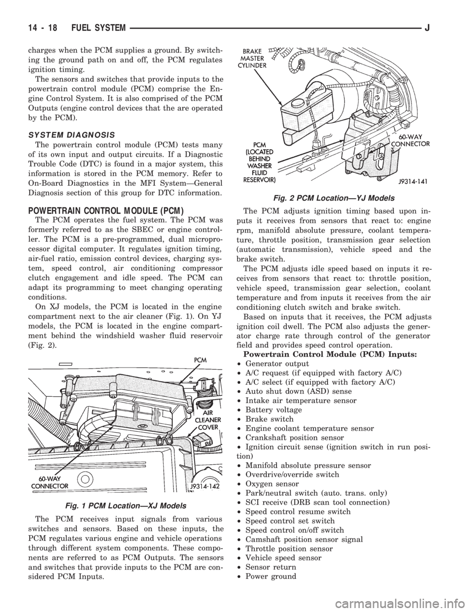
On XJ models, the PCM is located in the engine
compartment next to the air cleaner (Fig. 1). On YJ
models, the PCM is located in the engine compart-
ment behind the windshield washer fluid reservoir
(Fig. 2).
The PCM receives input signals from various
switches and sensors. Based on these inputs, the
PCM regulates various engine and vehicle operations
through different system components. These compo-
nents are referred to as PCM Outputs. The sensors
and switches that provide inputs to the PCM are con-
sidered PCM Inputs.The PCM adjusts ignition timing based upon in-
puts it receives from sensors that react to: engine
rpm, manifold absolute pressure, coolant tempera-
ture, throttle position, transmission gear selection
(automatic transmission), vehicle speed and the
brake switch.
The PCM adjusts idle speed based on inputs it re-
ceives from sensors that react to: throttle position,
vehicle speed, transmission gear selection, coolant
temperature and from inputs it receives from the air
conditioning clutch switch and brake switch.
Based on inputs that it receives, the PCM adjusts
ignition coil dwell. The PCM also adjusts the gener-
ator charge rate through control of the generator
field and provides speed control operation.
Powertrain Control Module (PCM) Inputs:
²Generator output
²A/C request (if equipped with factory A/C)
²A/C select (if equipped with factory A/C)
²Auto shut down (ASD) sense
²Intake air temperature sensor
²Battery voltage
²Brake switch
²Engine coolant temperature sensor
²Crankshaft position sensor
²Ignition circuit sense (ignition switch in run posi-
tion)
²Manifold absolute pressure sensor
²Overdrive/override switch
²Oxygen sensor
²Park/neutral switch (auto. trans. only)
²SCI receive (DRB scan tool connection)
²Speed control resume switch
²Speed control set switch
²Speed control on/off switch
²Camshaft position sensor signal
²Throttle position sensor
²Vehicle speed sensor
²Sensor return
²Power ground
Fig. 1 PCM LocationÐXJ Models
Fig. 2 PCM LocationÐYJ Models
14 - 18 FUEL SYSTEMJ
Page 982 of 1784
Refer to Group 8D, Ignition System for more crank-
shaft position sensor information.
The engine will not operate if the PCM does not re-
ceive a crankshaft position sensor input.
ENGINE COOLANT TEMPERATURE SENSORÐPCM
INPUT
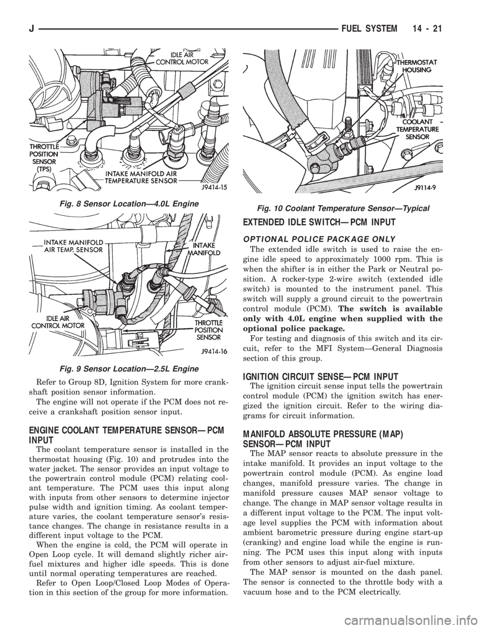
The coolant temperature sensor is installed in the
thermostat housing (Fig. 10) and protrudes into the
water jacket. The sensor provides an input voltage to
the powertrain control module (PCM) relating cool-
ant temperature. The PCM uses this input along
with inputs from other sensors to determine injector
pulse width and ignition timing. As coolant temper-
ature varies, the coolant temperature sensor's resis-
tance changes. The change in resistance results in a
different input voltage to the PCM.
When the engine is cold, the PCM will operate in
Open Loop cycle. It will demand slightly richer air-
fuel mixtures and higher idle speeds. This is done
until normal operating temperatures are reached.
Refer to Open Loop/Closed Loop Modes of Opera-
tion in this section of the group for more information.
EXTENDED IDLE SWITCHÐPCM INPUT
OPTIONAL POLICE PACKAGE ONLY
The extended idle switch is used to raise the en-
gine idle speed to approximately 1000 rpm. This is
when the shifter is in either the Park or Neutral po-
sition. A rocker-type 2-wire switch (extended idle
switch) is mounted to the instrument panel. This
switch will supply a ground circuit to the powertrain
control module (PCM).The switch is available
only with 4.0L engine when supplied with the
optional police package.
For testing and diagnosis of this switch and its cir-
cuit, refer to the MFI SystemÐGeneral Diagnosis
section of this group.
IGNITION CIRCUIT SENSEÐPCM INPUT
The ignition circuit sense input tells the powertrain
control module (PCM) the ignition switch has ener-
gized the ignition circuit. Refer to the wiring dia-
grams for circuit information.
MANIFOLD ABSOLUTE PRESSURE (MAP)
SENSORÐPCM INPUT
The MAP sensor reacts to absolute pressure in the
intake manifold. It provides an input voltage to the
powertrain control module (PCM). As engine load
changes, manifold pressure varies. The change in
manifold pressure causes MAP sensor voltage to
change. The change in MAP sensor voltage results in
a different input voltage to the PCM. The input volt-
age level supplies the PCM with information about
ambient barometric pressure during engine start-up
(cranking) and engine load while the engine is run-
ning. The PCM uses this input along with inputs
from other sensors to adjust air-fuel mixture.
The MAP sensor is mounted on the dash panel.
The sensor is connected to the throttle body with a
vacuum hose and to the PCM electrically.
Fig. 8 Sensor LocationÐ4.0L Engine
Fig. 9 Sensor LocationÐ2.5L Engine
Fig. 10 Coolant Temperature SensorÐTypical
JFUEL SYSTEM 14 - 21