1994 JEEP CHEROKEE tires
[x] Cancel search: tiresPage 1452 of 1784
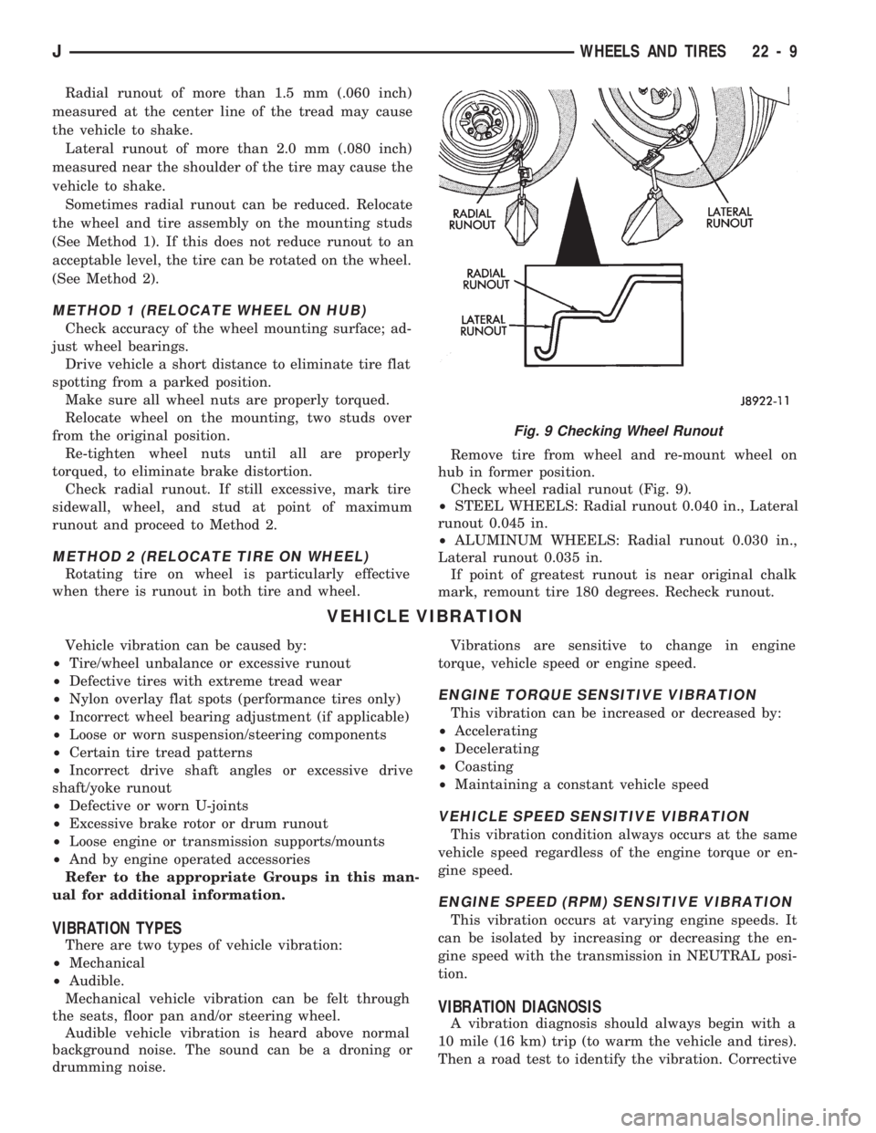
Radial runout of more than 1.5 mm (.060 inch)
measured at the center line of the tread may cause
the vehicle to shake.
Lateral runout of more than 2.0 mm (.080 inch)
measured near the shoulder of the tire may cause the
vehicle to shake.
Sometimes radial runout can be reduced. Relocate
the wheel and tire assembly on the mounting studs
(See Method 1). If this does not reduce runout to an
acceptable level, the tire can be rotated on the wheel.
(See Method 2).
METHOD 1 (RELOCATE WHEEL ON HUB)
Check accuracy of the wheel mounting surface; ad-
just wheel bearings.
Drive vehicle a short distance to eliminate tire flat
spotting from a parked position.
Make sure all wheel nuts are properly torqued.
Relocate wheel on the mounting, two studs over
from the original position.
Re-tighten wheel nuts until all are properly
torqued, to eliminate brake distortion.
Check radial runout. If still excessive, mark tire
sidewall, wheel, and stud at point of maximum
runout and proceed to Method 2.
METHOD 2 (RELOCATE TIRE ON WHEEL)
Rotating tire on wheel is particularly effective
when there is runout in both tire and wheel.Remove tire from wheel and re-mount wheel on
hub in former position.
Check wheel radial runout (Fig. 9).
²STEEL WHEELS: Radial runout 0.040 in., Lateral
runout 0.045 in.
²ALUMINUM WHEELS: Radial runout 0.030 in.,
Lateral runout 0.035 in.
If point of greatest runout is near original chalk
mark, remount tire 180 degrees. Recheck runout.
VEHICLE VIBRATION
Vehicle vibration can be caused by:
²Tire/wheel unbalance or excessive runout
²Defective tires with extreme tread wear
²Nylon overlay flat spots (performance tires only)
²Incorrect wheel bearing adjustment (if applicable)
²Loose or worn suspension/steering components
²Certain tire tread patterns
²Incorrect drive shaft angles or excessive drive
shaft/yoke runout
²Defective or worn U-joints
²Excessive brake rotor or drum runout
²Loose engine or transmission supports/mounts
²And by engine operated accessories
Refer to the appropriate Groups in this man-
ual for additional information.
VIBRATION TYPES
There are two types of vehicle vibration:
²Mechanical
²Audible.
Mechanical vehicle vibration can be felt through
the seats, floor pan and/or steering wheel.
Audible vehicle vibration is heard above normal
background noise. The sound can be a droning or
drumming noise.Vibrations are sensitive to change in engine
torque, vehicle speed or engine speed.
ENGINE TORQUE SENSITIVE VIBRATION
This vibration can be increased or decreased by:
²Accelerating
²Decelerating
²Coasting
²Maintaining a constant vehicle speed
VEHICLE SPEED SENSITIVE VIBRATION
This vibration condition always occurs at the same
vehicle speed regardless of the engine torque or en-
gine speed.
ENGINE SPEED (RPM) SENSITIVE VIBRATION
This vibration occurs at varying engine speeds. It
can be isolated by increasing or decreasing the en-
gine speed with the transmission in NEUTRAL posi-
tion.
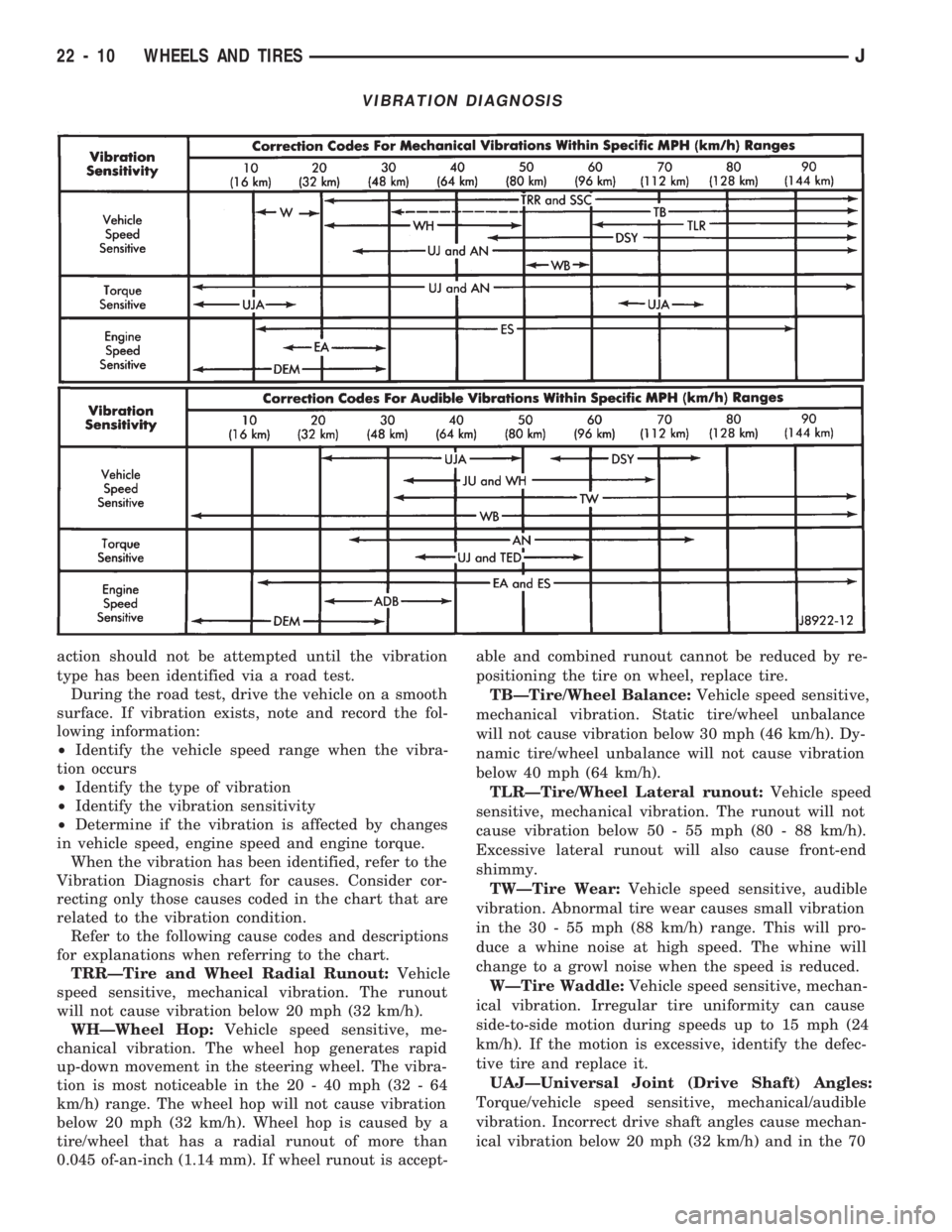
VIBRATION DIAGNOSIS
A vibration diagnosis should always begin with a
10 mile (16 km) trip (to warm the vehicle and tires).
Then a road test to identify the vibration. Corrective
Fig. 9 Checking Wheel Runout
JWHEELS AND TIRES 22 - 9
Page 1453 of 1784
action should not be attempted until the vibration
type has been identified via a road test.
During the road test, drive the vehicle on a smooth
surface. If vibration exists, note and record the fol-
lowing information:
²Identify the vehicle speed range when the vibra-
tion occurs
²Identify the type of vibration
²Identify the vibration sensitivity
²Determine if the vibration is affected by changes
in vehicle speed, engine speed and engine torque.
When the vibration has been identified, refer to the
Vibration Diagnosis chart for causes. Consider cor-
recting only those causes coded in the chart that are
related to the vibration condition.
Refer to the following cause codes and descriptions
for explanations when referring to the chart.
TRRÐTire and Wheel Radial Runout:Vehicle
speed sensitive, mechanical vibration. The runout
will not cause vibration below 20 mph (32 km/h).
WHÐWheel Hop:Vehicle speed sensitive, me-
chanical vibration. The wheel hop generates rapid
up-down movement in the steering wheel. The vibra-
tion is most noticeable in the 20 - 40 mph (32 - 64
km/h) range. The wheel hop will not cause vibration
below 20 mph (32 km/h). Wheel hop is caused by a
tire/wheel that has a radial runout of more than
0.045 of-an-inch (1.14 mm). If wheel runout is accept-able and combined runout cannot be reduced by re-
positioning the tire on wheel, replace tire.
TBÐTire/Wheel Balance:Vehicle speed sensitive,
mechanical vibration. Static tire/wheel unbalance
will not cause vibration below 30 mph (46 km/h). Dy-
namic tire/wheel unbalance will not cause vibration
below 40 mph (64 km/h).
TLRÐTire/Wheel Lateral runout:Vehicle speed
sensitive, mechanical vibration. The runout will not
cause vibration below 50 - 55 mph (80 - 88 km/h).
Excessive lateral runout will also cause front-end
shimmy.
TWÐTire Wear:Vehicle speed sensitive, audible
vibration. Abnormal tire wear causes small vibration
in the 30 - 55 mph (88 km/h) range. This will pro-
duce a whine noise at high speed. The whine will
change to a growl noise when the speed is reduced.
WÐTire Waddle:Vehicle speed sensitive, mechan-
ical vibration. Irregular tire uniformity can cause
side-to-side motion during speeds up to 15 mph (24
km/h). If the motion is excessive, identify the defec-
tive tire and replace it.
UAJÐUniversal Joint (Drive Shaft) Angles:
Torque/vehicle speed sensitive, mechanical/audible
vibration. Incorrect drive shaft angles cause mechan-
ical vibration below 20 mph (32 km/h) and in the 70
VIBRATION DIAGNOSIS
22 - 10 WHEELS AND TIRESJ
Page 1454 of 1784
mph (112 km/h) range. The incorrect angles can also
produce an audible vibration in the 20 - 50 mph (32 -
80 km/h) range. Caster adjustment could be required
to correct the angles.
UJÐUniversal Joints:Engine torque/vehicle
speed sensitive, mechanical/audible vibration. If the
U-joint is worn it will cause vibration with almost
any vehicle speed/engine torque condition.
DSYÐDrive Shaft and Yokes:Vehicle speed sen-
sitive, mechanical/audible vibration. The condition
will not cause vibration below 35 mph (56 km/h). Ex-
cessive runout, unbalance or dents and bends in the
shaft will cause the vibration. Identify the actual
cause and repair/replace as necessary.
WBÐWheel Bearings:Vehicle speed sensitive,
mechanical/audible vibration. Loose wheel bearings
cause shimmy-like vibration at 35 mph (56 km/h)
and above. Worn bearings will also produce a growl
noise at low vehicle speed and a whine noise at high
vehicle speed. The wheel bearings must be adjusted
or replaced, as applicable.
ANÐAxle Noise:Engine torque/vehicle speed sen-
sitive, mechanical/audible vibration. The axle will not
cause mechanical vibration unless the axle shaft is
bent. Worn or damaged axle pinion shaft or differen-
tial gears and bearings will cause noise. Replace the
defective component(s) as necessary.
SSCÐSuspension and Steering Components:
Vehicle speed sensitive, mechanical vibration. Wornsuspension/steering components can cause mechani-
cal vibration at speeds above 20 mph (32 km/h).
Identify and repair or replace the defective compo-
nent(s).
EAÐEngine Driven Accessories:Engine speed
sensitive, mechanical/audible vibration. Vibration can
be caused by loose or broken A/C compressor, PS
pump, water pump, generator or brackets, etc. Usu-
ally more noticeable when the transmission is shifted
into the NEUTRAL position and the engine speed
(rpm) increased. Inspect the engine driven accesso-
ries in the engine compartment. Repair/replace as
necessary.
ADBÐAccessory Drive Belts:Engine speed sen-
sitive, audible vibration. Worn drive belts can cause a
vibration that produces either a droning, fluttering or
rumbling noise. Inspect the drive belt(s) and tighten/
replace as necessary.
DEMÐDamaged Engine or Transmission Sup-
port Mounts:Engine speed sensitive, mechanical/
audible vibration. If a support mount is worn, noise
or vibration will occur. Inspect the support mounts
and repair/replace as necessary.
ESÐExhaust System:Engine speed sensitive,
mechanical/audible vibration. If loose exhaust compo-
nents contact the vehicle body they will cause noise
and vibration. Inspect the exhaust system for loose,
broken and mis-aligned components and repair/re-
place as necessary.
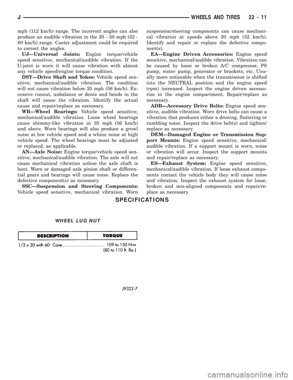
SPECIFICATIONS
WHEEL LUG NUT
JWHEELS AND TIRES 22 - 11
Page 1543 of 1784
The reinforcement bracket is held on the
frame rail with two blind rivets.
(2) Remove the bracket and tow hook from frame
rail.
INSTALLATION
(1) Position bracket and tow hook on the frame
rail.
(2) Install bolts that attach tow hook bracket to
frame rail and reinforcement bracket. Tighten bolts
to 75 Nzm (55 ft-lbs) torque.
TRAILER HITCHES
CLASS III HITCHÐXJ VEHICLES
A class III weight-distributing/equalizer type hitch
can be used to tow a trailer:
²having a maximum gross weight of 5,000 lbs/2250
kg, and
²having a maximum tongue weight of 750 lbs/332
kg).
The following vehicle basic equipment is required
for class III trailer towing:
²P205/75R15 or larger tires;
²full size spare tire;
²trailer sway control;
²trailer tow wire harness and connector;
²heavy duty turn signal flasher element;
²heavy duty axle (with synthetic lubricant);²heavy duty cooling system;
²heavy duty generator/battery;
²auxiliary automatic transmission fluid cooler; and
²I-6, 4.0L engine.
Wide-angle type door mirrors are recommended but
not required.
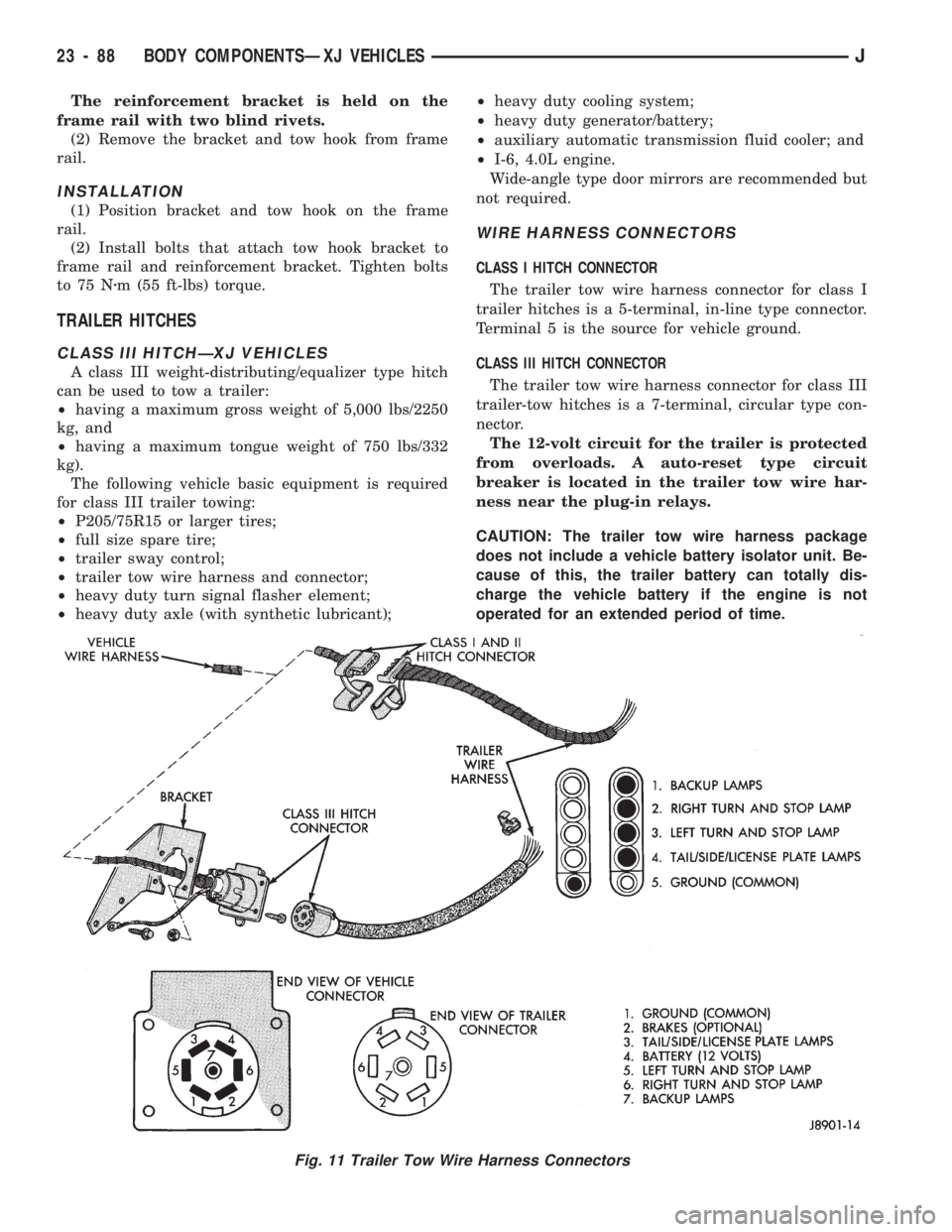
WIRE HARNESS CONNECTORS
CLASS I HITCH CONNECTOR
The trailer tow wire harness connector for class I
trailer hitches is a 5-terminal, in-line type connector.
Terminal 5 is the source for vehicle ground.
CLASS III HITCH CONNECTOR
The trailer tow wire harness connector for class III
trailer-tow hitches is a 7-terminal, circular type con-
nector.
The 12-volt circuit for the trailer is protected
from overloads. A auto-reset type circuit
breaker is located in the trailer tow wire har-
ness near the plug-in relays.
CAUTION: The trailer tow wire harness package
does not include a vehicle battery isolator unit. Be-
cause of this, the trailer battery can totally dis-
charge the vehicle battery if the engine is not
operated for an extended period of time.
Fig. 11 Trailer Tow Wire Harness Connectors
23 - 88 BODY COMPONENTSÐXJ VEHICLESJ
Page 1583 of 1784
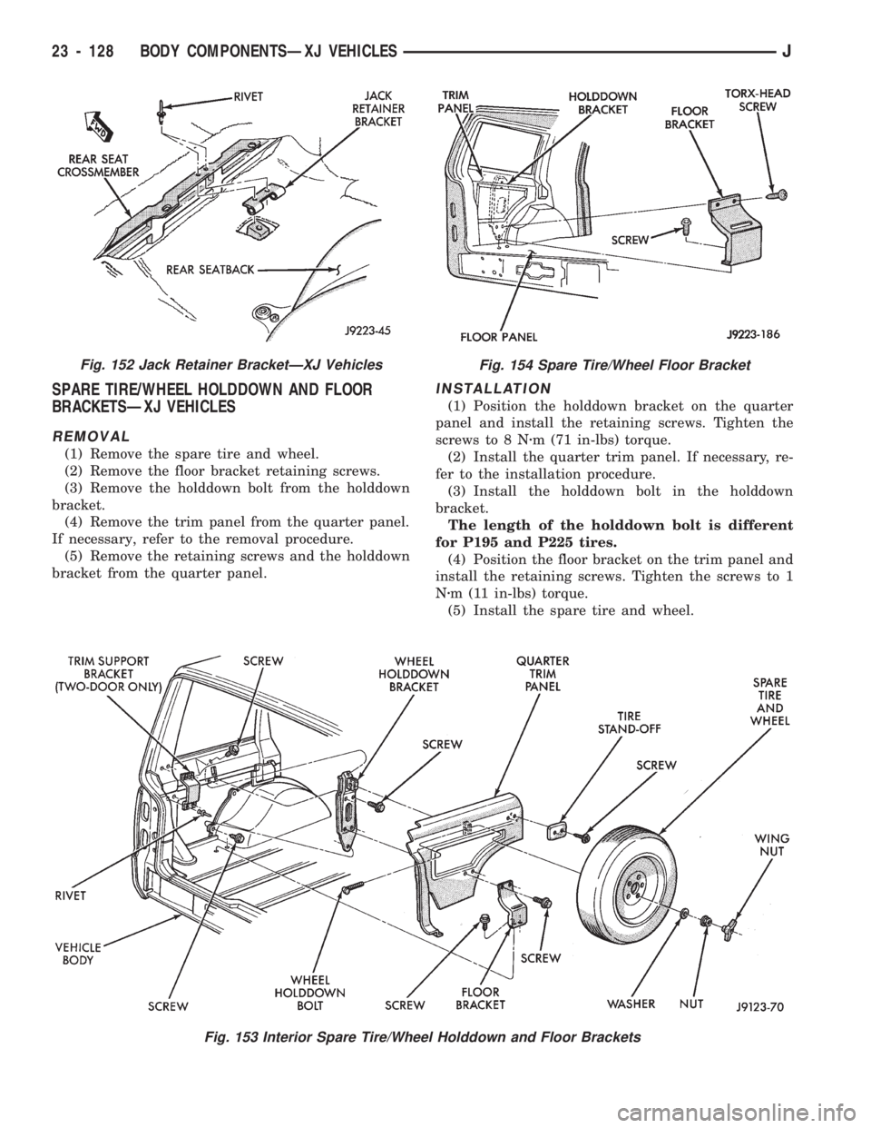
SPARE TIRE/WHEEL HOLDDOWN AND FLOOR
BRACKETSÐXJ VEHICLES
REMOVAL
(1) Remove the spare tire and wheel.
(2) Remove the floor bracket retaining screws.
(3) Remove the holddown bolt from the holddown
bracket.
(4) Remove the trim panel from the quarter panel.
If necessary, refer to the removal procedure.
(5) Remove the retaining screws and the holddown
bracket from the quarter panel.
INSTALLATION
(1) Position the holddown bracket on the quarter
panel and install the retaining screws. Tighten the
screws to 8 Nzm (71 in-lbs) torque.
(2) Install the quarter trim panel. If necessary, re-
fer to the installation procedure.
(3) Install the holddown bolt in the holddown
bracket.
The length of the holddown bolt is different
for P195 and P225 tires.
(4) Position the floor bracket on the trim panel and
install the retaining screws. Tighten the screws to 1
Nzm (11 in-lbs) torque.
(5) Install the spare tire and wheel.
Fig. 153 Interior Spare Tire/Wheel Holddown and Floor Brackets
Fig. 152 Jack Retainer BracketÐXJ VehiclesFig. 154 Spare Tire/Wheel Floor Bracket
23 - 128 BODY COMPONENTSÐXJ VEHICLESJ
Page 1731 of 1784
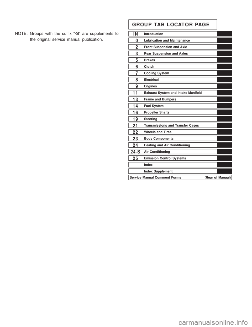
NOTE: Groups with the suffix ª-Sº are supplements to
the original service manual publication.
GROUP TAB LOCATOR PAGE
INIntroduction
0Lubrication and Maintenance
2Front Suspension and Axle
3Rear Suspension and Axles
5Brakes
6Clutch
7Cooling System
8Electrical
9Engines
11Exhaust System and Intake Manifold
13Frame and Bumpers
14Fuel System
16Propeller Shafts
19Steering
21Transmissions and Transfer Cases
22Wheels and Tires
23Body Components
24Heating and Air Conditioning
24-SAir Conditioning
25Emission Control Systems
Index
Index Supplement
Service Manual Comment Forms (Rear of Manual)
Page 1737 of 1784
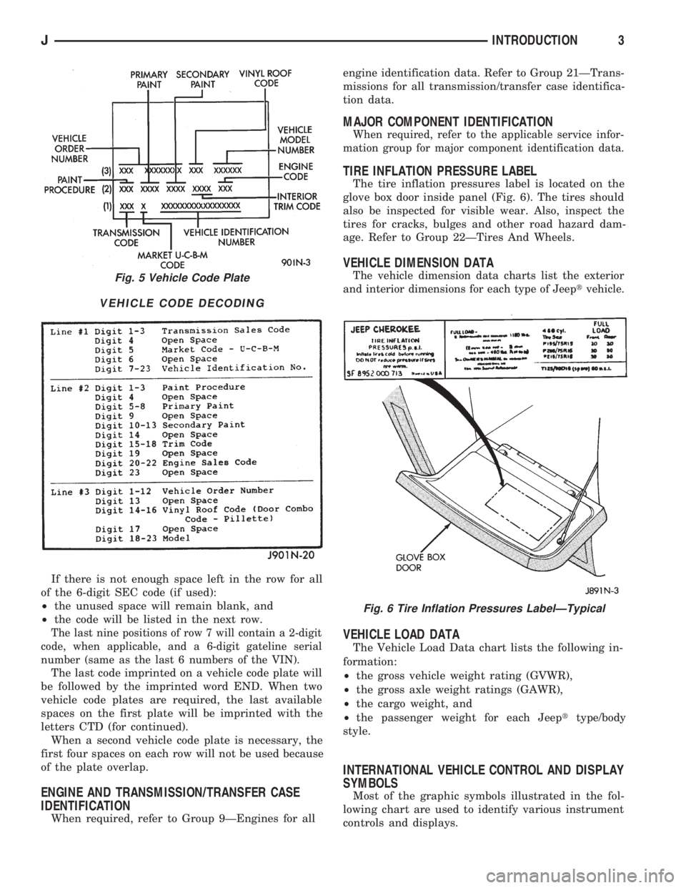
If there is not enough space left in the row for all
of the 6-digit SEC code (if used):
²the unused space will remain blank, and
²the code will be listed in the next row.
The last nine positions of row 7 will contain a 2-digit
code, when applicable, and a 6-digit gateline serial
number (same as the last 6 numbers of the VIN).
The last code imprinted on a vehicle code plate will
be followed by the imprinted word END. When two
vehicle code plates are required, the last available
spaces on the first plate will be imprinted with the
letters CTD (for continued).
When a second vehicle code plate is necessary, the
first four spaces on each row will not be used because
of the plate overlap.
ENGINE AND TRANSMISSION/TRANSFER CASE
IDENTIFICATION
When required, refer to Group 9ÐEngines for allengine identification data. Refer to Group 21ÐTrans-
missions for all transmission/transfer case identifica-
tion data.
MAJOR COMPONENT IDENTIFICATION
When required, refer to the applicable service infor-
mation group for major component identification data.
TIRE INFLATION PRESSURE LABEL
The tire inflation pressures label is located on the
glove box door inside panel (Fig. 6). The tires should
also be inspected for visible wear. Also, inspect the
tires for cracks, bulges and other road hazard dam-
age. Refer to Group 22ÐTires And Wheels.
VEHICLE DIMENSION DATA
The vehicle dimension data charts list the exterior
and interior dimensions for each type of Jeeptvehicle.
VEHICLE LOAD DATA
The Vehicle Load Data chart lists the following in-
formation:
²the gross vehicle weight rating (GVWR),
²the gross axle weight ratings (GAWR),
²the cargo weight, and
²the passenger weight for each Jeepttype/body
style.
INTERNATIONAL VEHICLE CONTROL AND DISPLAY
SYMBOLS
Most of the graphic symbols illustrated in the fol-
lowing chart are used to identify various instrument
controls and displays.
Fig. 5 Vehicle Code Plate
VEHICLE CODE DECODING
Fig. 6 Tire Inflation Pressures LabelÐTypical
JINTRODUCTION3
Page 1748 of 1784
CARPET/FLOOR MATS.................23-198
CARPET/MATÐXJ VEHICLES, FRONT.....23-129
CARPET/MATÐXJ VEHICLES, REAR......23-130
CARPETS AND FLOOR MATS............23-129
CARRIER, EXTERNAL SPARE/WHEEL
TIRE..............................23-172
CASE ASSEMBLY, TRANSFER......21-282,21-306
CASE CLEANING AND INSPECTION,
TRANSMISSION.....................21-118
CASE COVER OIL SEAL REPLACEMENT,
TIMING.........................9-26,9-67
CASE COVER, TIMING...............9-27,9-67
CASE DISASSEMBLY AND OVERHAUL,
TRANSFER...................21-277,21-297
CASE FILL LEVEL, TRANSFER...........21-294
CASE IDENTIFICATION, ENGINE AND
TRANSMISSION/TRANSFER..........INTRO.-3
CASE IDENTIFICATION, TRANSFER . 21-273,21-293
CASE INSTALLATION, TRANSFER . . . 21-276,21-296
CASE, LEGEND FOR NP231 TRANSFER....21-292
CASE, LEGEND FOR NP242 TRANSFER....21-319
CASE LUBRICANT, TRANSFER.....21-273,21-294
CASE, NP231 TRANSFER.........21-272,21-291
CASE, NP242 TRANSFER...............21-293
CASE OVERHAUL, FIRST-REVERSE
BRAKE PISTON AND TRANSMISSION....21-237
CASE REMOVAL, TRANSFER......21-276,21-296
CASE SPECIFICATIONS, TRANSMISSION/
TRANSFER.........................21-320
CASE, TRANSFER.......................0-25
CATALYTIC CONVERTER..............11-1,11-5
CATALYTIC CONVERTER/MUFFLER/
TAILPIPE SUPPORT BRACKETS.........23-85
CAUSES, CLUTCH PROBLEM...............6-3
CENTER HIGH MOUNTED STOP LAMP
(CHMSL)ÐXJ.......................8L-10
CENTER HIGH MOUNTED STOP LAMP
(CHMSL)ÐYJ.......................8L-11
CERTIFICATION LABEL, VEHICLE SAFETY . INTRO.-1
CHAIN AND SPROCKETS, TIMING......9-28,9-68
CHANGE AND FILTER REPLACEMENT,
ENGINE OIL..........................0-15
CHANGE, LUBRICANT; FRONT
SUSPENSION AND AXLE................2-22
CHANGE, LUBRICANT; REAR SUSPENSION
AND AXLES......................3-13,3-30
CHARGE RATE.........................8A-6
CHARGE, SYSTEM......................24-5
CHARGING, BATTERY....................8A-5
CHARGING TIME TABLE, BATTERY.........8A-5
CHASSIS AND BODY COMPONENTS........0-30
CHASSIS COMPONENT AND WHEEL
BEARING LUBRICANTS.................0-30
CHECK BALL DIMENSIONS, AW-4 VALVE
BODY.............................21-328
CHECK ENGINE LAMP FOR DIAGNOSTIC
TROUBLE CODES, INDICATOR..........8A-19
CHECK ENGINE, MALFUNCTION
INDICATOR LAMP; INSTRUMENT PANEL
AND GAUGESÐXJ................8E-2,8E-4
CHECK ENGINE, MALFUNCTION
INDICATOR LAMP; INSTRUMENT PANEL
AND GAUGESÐYJ...................8E-16
CHECK, PRELIMINARY BRAKE..............5-7
CHECK (ROAD TEST), OPERATIONAL.......8H-7
CHECK VALVE REPLACEMENT............19-33
CHECK VALVE TEST, POWER BOOSTER......5-11
CHECK WITH BATTERY INDICATOR
(BASE CLUSTER ONLY), OPERATIONAL . . . 8A-14
CHECK WITH VOLTMETER, OPERATIONAL . . . 8A-15
CHECKING FLUID LEVEL AND
CONDITION...................21-96,21-173
CHECKING FOR DIAGNOSTIC TROUBLE
CODE...............................8H-5
CHECKS FIRST, SYMPTOM AND ACTIONÐ
SEE PRELIMINARY.....................7-6
CHECKS, PRELIMINARY...................7-5
CHIP PROTECTION, STONE.............23-201
CHMSLÐXJ, CENTER HIGH MOUNTED
STOP LAMP.........................8L-10
CHMSLÐYJ, CENTER HIGH MOUNTED
STOP LAMP
.........................8L-11
CIRCUIT DIAGNOSIS, IGNITION
SECONDARY
........................8D-12
CIRCUIT IDENTIFICATION
................8W-2
CIRCUIT, PRINTED
.....................8E-22CIRCUIT REMOVAL, PRINTED............8E-24
CIRCUIT REPLACEMENT, PRINTED........8E-19
CIRCUIT REPLACEMENTÐINSTRUMENT
CLUSTER REMOVED, PRINTED...........8E-6
CIRCUIT SENSEÐPCM INPUT, IGNITION....14-21
CIRCUIT TESTS - (VOLTAGE DROP
METHOD), STARTER FEED..............8A-9
CIRCUIT TESTS, STARTER CONTROL......8A-11
CIRCUIT VOLTAGE, BATTERY OPEN.........8A-4
CIRCUIT VOLTAGE TEST, BATTERY OPEN....8A-3
CIRCUITS, ABS SYSTEM WIRING AND
ELECTRICAL..........................5-4
CLAMPS, FUEL TUBES/LINES/HOSES . . 14-9,14-56
CLASSIFICATION OF LUBRICANTS...........0-2
CLASSIFICATIONS AND RATINGS,
BATTERY............................8A-8
CLASSIFICATIONS AND RATINGSÐ
LEFT HAND DRIVE, BATTERY...........8B-10
CLASSIFICATIONS AND RATINGSÐ
RIGHT HAND DRIVE, BATTERY..........8B-10
CLEAN BRAKE FLUID, IMPORTANCE OF.....5-48
CLEANER, AIR.........................25-7
CLEANER FILTER ELEMENT, ENGINE AIR....0-16
CLEANER HOUSING, AIR; EMISSION
CONTROL SYSTEMS...................25-8
CLEANER HOUSING, AIR; FUEL SYSTEM....14-54
CLEANING AND INSPECTION . 21-13,21-204,21-305
CLEANING AND INSPECTION, CALIPER......5-28
CLEANING AND INSPECTION, GEAR.......19-40
CLEANING AND INSPECTION,
TRANSMISSION CASE................21-118
CLEANING OF TIRES....................22-2
CLEANING/INSPECTION; FRONT
SUSPENSION AND AXLE................2-35
CLEANING/INSPECTION; REAR
SUSPENSION AND AXLES...............3-18
CLEANING/REVERSE FLUSHING,
COOLING SYSTEM....................7-17
CLEARANCE, AW-4 BUSHING AND
PISTON...........................21-326
CLIMATE CONTROL SYSTEMÐXJ VEHICLES . 24-22
CLIMATE CONTROL SYSTEMÐYJ VEHICLES . 24-37
CLIP, FUEL AND BRAKE FLUID TUBE
RETAINER; BODY COMPONENTSÐXJ
VEHICLES..........................23-86
CLIP, FUEL AND BRAKE FLUID TUBE
RETAINER; FRAME AND BUMPERS.......13-16
CLUSTER AND GAUGE HOUSINGS,
INSTRUMENT......................23-190
CLUSTER BEZEL, INSTRUMENT.....23-91,23-191
CLUSTER BULB REPLACEMENT,
INSTRUMENT.......................8E-19
CLUSTER DIAGNOSIS, INSTRUMENT;
INSTRUMENT PANEL AND
GAUGESÐXJ.........................8E-3
CLUSTER DIAGNOSIS, INSTRUMENT;
INSTRUMENT PANEL AND GAUGESÐYJ . . 8E-14
CLUSTER GAUGES, INSTRUMENT;
INSTRUMENT PANEL AND GAUGESÐXJ . . 8E-13
CLUSTER GAUGES, INSTRUMENT;
INSTRUMENT PANEL AND GAUGESÐYJ . . 8E-27
CLUSTER GENERAL INFORMATION,
INSTRUMENT; INSTRUMENT PANEL AND
GAUGESÐXJ.........................8E-1
CLUSTER GENERAL INFORMATION,
INSTRUMENT; INSTRUMENT PANEL
AND GAUGESÐYJ...................8E-14
CLUSTER, HIGH LINE...................8E-12
CLUSTER, INSTRUMENT................8E-15
CLUSTER, LOW LINE...................8E-11
CLUSTER REMOVED, GAUGE
REPLACEMENTÐINSTRUMENT..........8E-5
CLUSTER REMOVED, GEAR SELECTOR
INDICATOR REPLACEMENTÐ
INSTRUMENT........................8E-6
CLUSTER REMOVED, PRINTED CIRCUIT
REPLACEMENTÐINSTRUMENT..........8E-6
CLUSTER REMOVED, SPEEDOMETER
REPLACEMENTÐINSTRUMENT..........8E-5
CLUSTER REMOVED, TACHOMETER
REPLACEMENTÐINSTRUMENT
..........8E-5
CLUSTER REPLACEMENT, GAUGE
.........8E-24
CLUSTER REPLACEMENT, INSTRUMENT;
INSTRUMENT PANEL AND GAUGESÐXJ
. . . 8E-5
CLUSTER REPLACEMENT, INSTRUMENT;
INSTRUMENT PANEL AND GAUGESÐYJ
. . 8E-17CLUSTER SERVICE PROCEDURES,
INSTRUMENT; INSTRUMENT PANEL AND
GAUGESÐXJ.........................8E-5
CLUSTER SERVICE PROCEDURES,
INSTRUMENT; INSTRUMENT PANEL AND
GAUGESÐYJ........................8E-17
CLUSTER/SWITCH/LIGHTER/RADIO/HEVAC,
INSTRUMENT.......................23-91
CLUSTERS, INSTRUMENT...............8E-10
CLUTCH AND BRAKE PACK
REQUIREMENTS, AW-4...............21-328
CLUTCH AND OUTPUT SHAFT
OVERHAUL, NO. 2 ONE-WAY..........21-234
CLUTCH COMPONENT LUBRICATION.........6-1
CLUTCH COMPONENTS
...................6-1
CLUTCH COVER AND DISC INSTALLATION
....6-10
CLUTCH COVER AND DISC REMOVAL
.......6-10
CLUTCH DIAGNOSIS
.....................6-3
CLUTCH DISC AND PLATE THICKNESS,
AW-4
.............................21-325
CLUTCH FLUID LEVEL
...................6-14
CLUTCH HOUSING REPLACEMENT
.........6-11
CLUTCH, HYDRAULIC
....................0-22
CLUTCH HYDRAULIC LINKAGE
INSTALLATION
........................6-12
CLUTCH HYDRAULIC LINKAGE REMOVAL
....6-11
CLUTCH INSPECTION, TORQUE
CONVERTER STATOR
................21-189
CLUTCH LINKAGE FLUID
..................6-1
CLUTCH, MAGNETIC
....................24-18
CLUTCH OPERATION
.....................6-2
CLUTCH OVERHAUL, DIRECT
............21-219
CLUTCH OVERHAUL, FORWARD
.........21-223
CLUTCH OVERHAUL, FRONT
............21-125
CLUTCH OVERHAUL, OVERDRIVE
PLANETARY GEAR
...................21-209
CLUTCH OVERHAUL, REAR
.............21-128
CLUTCH OVERHAUL, SUN GEAR AND
NO. 1ONE-WAY
.....................21-229
CLUTCH PEDAL INSTALLATION
............6-15
CLUTCH PEDAL REMOVAL
................6-15
CLUTCH PROBLEM CAUSES
...............6-3
CLUTCH RELAY, AIR CONDITIONING
.......14-54
CLUTCH RELAYÐPCM OUTPUT, AIR
CONDITIONING
......................14-24
CLUTCH RELAYÐPCM OUTPUT, TORQUE
CONVERTER
........................14-27
CLUTCH RELAY TEST, TORQUE
CONVERTER
........................14-45
CLUTCH RELAY, TORQUE CONVERTER
.....14-60
CLUTCH SAFETY PRECAUTIONS
...........6-10
CLUTCH SERVICE
.......................6-10
CLUTCHÐLOW-REVERSE DRUMÐREAR
SUPPORT OVERHAUL, OVERRUNNING
. . . 21-118
COAT, BASE/COLOR
...................23-201
CODE, CHECKING FOR DIAGNOSTIC
TROUBLE
...........................8H-5
CODE DECODING, VEHICLE
...........INTRO.-3
CODE (DTC), DIAGNOSTIC TROUBLE
.......14-51
CODE (DTC), GENERATOR DIAGNOSTIC
TROUBLE
...........................8A-19
CODE IDENTIFICATION, WIRE
.............8W-2
CODE LETTERS, JEEP BODY
...............5-2
CODE PLATE, VEHICLE
...............INTRO.-2
CODES AND DIMENSIONS,
DESIGNATIONS, LABELS/PLATES,
.....INTRO.-1
CODES, INDICATOR (CHECK ENGINE)
LAMP FOR DIAGNOSTIC TROUBLE
.......8A-19
CODES, VEHICLE DESIGNATION
........INTRO.-1
CODES, XJ EXTERIOR PAINT
............23-205
CODES, XJ INTERIOR PAINT
............23-205
CODES, YJ EXTERIOR PAINT
............23-206
CODES, YJ INTERIOR PAINT
............23-206
COIL, EVAPORATOR
....................24-34
COIL, IGNITION; FUEL SYSTEM
...........14-57
COIL, IGNITION; IGNITION SYSTEMS
. 8D-4,8D-11,
8D-26
COILÐPCM OUTPUT, IGNITION
...........14-26
COIL RESISTANCE, IGNITION
............8D-11
COIL SPRING
..........................2-13
4 INDEXJ
Description Group-Page Description Group-Page Description Group-Page