1994 JEEP CHEROKEE wheel
[x] Cancel search: wheelPage 26 of 1784

DRAINING ATF/FILTER REMOVAL
Drain the automatic transmission fluid (ATF) im-
mediately after stopping the engine (before the ATF
cools).
(1) Raise and support the vehicle.
(2) Loosen the transmission pan bolts and drain
the original ATF into an appropriate container. Re-
move the pan bolts, the pan and the gasket.
Care should be exercised when disposing used
ATF after it has been drained from a vehicle
transmission.
(3) Remove the screws and the ATF filter (Fig. 8).
Discard the filter.
FILTER INSTALLATION/ATF RE-FILL
(1) Install a replacement ATF filter. Tighten the
screws with 4 NIm (35 in. lbs.) torque.
(2) Clean the pan thoroughly. Install a replace-
ment gasket on the pan. Install the pan with the at-
taching bolts:
²model AW-4 transmission Ð tighten the pan bolts
with 7 NIm (60 in. lbs.) torque; and
²model 998 transmission Ð tighten the pan bolts
with 17 NIm (150 in. lbs.) torque.
(3) Remove the support and lower the vehicle.
(4) Pour approximately 4.7 liters (5 quarts) of ATF
into the filler tube. Use MerconŸ ATF for AW-4 au-
tomatic transmissions. Use MOPAR ATF PLUS type
7176 or equivalent, for 998 automatic transmissions.
(5) Place a block in front of and at the rear of one
wheel/tire to prevent vehicle movement.
(6) Start the engine and allow it to idle a few min-
utes.
(7) Apply the brake pedal and engage the parking
brake. Move the transmission selector lever through
all positions, then place the selector lever in NEU-
TRAL position.(8) With the transmission at normal operating
temperature, observe the ATF level on the dipstick.
Add ATF (if necessary) to raise the level to the
FULL mark on the dipstick.Only 0.5 liter (1.0 pint)
will raise the level from the ADD mark to the
FULL mark when the ATF is at normal operat-
ing temperature.
(9) Inspect for fluid leaks and correct as necessary.
(10) Remove the wheel/tire blocks.
TRANSFER CASE
RECOMMENDED MAINTENANCE
The fluid (ATF) level in transfer cases should be
determined at the same time as the engine oil is
changed and the oil filter is replaced. Add ATF as
necessary.
In addition, transfer case ATF should be changed
after each 48 000-km (30,000-miles) interval of vehi-
cle operation has elapsed.
FLUID SPECIFICATIONS
If it is necessary to add fluid to a transfer case (or
when the fluid is changed), use MOPAR ATF PLUS
type 7176 or an equivalent MerconŸ/Dexron IIŸ
ATF.
FLUID LEVEL
The transfer case fill-hole plug is located at the
rear of the housing (Fig. 9).
Determine the transfer case fluid (ATF) level ac-
cording to the following procedure.
(1) Raise and support the vehicle.
(2) Remove the fill-hole plug from the transfer
case. The ATF level should be at the bottom edge of
the fill hole. The level can be slightly below the bot-
tom edge of the fill hole if the fluid is cold.
Fig. 9 Transfer CaseÐTypical
Fig. 8 ATF FilterÐTypical
JLUBRICATION AND MAINTENANCE 0 - 25
Page 30 of 1784
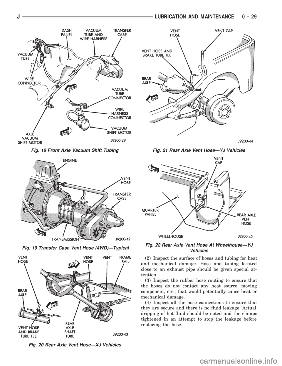
(2) Inspect the surface of hoses and tubing for heat
and mechanical damage. Hose and tubing located
close to an exhaust pipe should be given special at-
tention.
(3) Inspect the rubber hose routing to ensure that
the hoses do not contact any heat source, moving
component, etc., that would potentially cause heat or
mechanical damage.
(4) Inspect all the hose connections to ensure that
they are secure and there is no fluid leakage. Actual
dripping of hot fluid should be noted and the clamps
tightened in an attempt to stop the leakage before
replacing the hose.
Fig. 18 Front Axle Vacuum Shift Tubing
Fig. 19 Transfer Case Vent Hose (4WD)ÐTypical
Fig. 20 Rear Axle Vent HoseÐXJ Vehicles
Fig. 21 Rear Axle Vent HoseÐYJ Vehicles
Fig. 22 Rear Axle Vent Hose At WheelhouseÐYJ
Vehicles
JLUBRICATION AND MAINTENANCE 0 - 29
Page 31 of 1784

CHASSIS AND BODY COMPONENTS
INDEX
page page
Body Components........................ 34
Chassis Component and Wheel Bearing
Lubricants............................ 30
Front Wheel Bearings..................... 31
Headlamps............................. 35Manual Steering GearÐYJ Vehicles.......... 32
Power Brake System...................... 32
Power Steering System.................... 31
Steering Linkage and Ball Studs............. 30
Tires.................................. 34
CHASSIS COMPONENT AND WHEEL BEARING
LUBRICANTS
The chassis component and wheel bearing lubri-
cants that are recommended for Jeeptvehicles are
identified by the NLGI Certification Symbol (Fig. 1).
The symbol contains a coded designation that identi-
fies the usage and quality of the lubricant.
The letterGdesignates wheel bearing lubricant.
LetterLdesignates chassis lubricant. When the let-
ters are combined the lubricant can be used for dual
applications. The suffix lettersCandBdesignate the
level of the lubricant for the application. The letterC
represents level available for wheel bearing lubricant
(G) and the letterBrepresents level available for
chassis lubricant (L).
STEERING LINKAGE AND BALL STUDS
RECOMMENDED MAINTENANCE
The general condition of the steering linkage (Fig.
2) should be inspected and the ball studs should be
lubricated:
²2WD vehicles Ð after each 24 000-km (15,000-
miles) or six-months interval of vehicle operation has
elapsed; or
²4WD vehicles Ð after each 12 000-km (7,500-
miles) or six-months interval of vehicle operation has
elapsed.
LUBRICANT SPECIFICATION
Steering linkage should be lubricated with a dual-
purpose, lithium-base lubricant that is identified as
NLGI GC-LB lubricant.
INSPECTION/LUBRICATION
(1) Inspect the steering linkage. Examine the tie
rods and the drag link for bending, and the ball
studs for looseness and excessive wear.
(2) Replace, as necessary, all torn/ruptured ball-
stud seals and damaged/defective steering linkage
components.
CAUTION: Use care to prevent lubricant from con-
tacting the brake rotors.
(3) Lubricate the ball studs:
²clean the tips of the Zerk type lubrication fittings
on the tie-rod and drag-link ball-stud ends to avoid
lubricant contamination;
²lubricate the ball studs with high quality, dual-
purpose, lithium base chassis/wheel bearing lubri-
cant (NLGI GC-LB lubricant);
²cease the lubricant pressure when lubricant begins
to freely exit the base of the seal, or if the seal be-
gins to expand; and
²wipe the excess lubricant from the exterior sur-
faces of the ball joints and the adjacent surfaces.
Fig. 1 NLGI Lubricant Container Certification/
Identification Symbol
Fig. 2 Steering Components (XJ)ÐTypical
0 - 30 LUBRICATION AND MAINTENANCEJ
Page 32 of 1784
FRONT WHEEL BEARINGS
Only 2WD XJ vehicles are equipped with front
wheel bearings. XJ vehicles have semi-floating axle
shafts and axle shaft bearings that are lubricated via
differential lube oil.
RECOMMENDED MAINTENANCEÐ2WD XJ
VEHICLES
The front wheel bearings should be lubricated (re-
packed) at the same time as front brake pad/caliper
service is conducted.
LUBRICANT SPECIFICATION
Wheel bearings should be lubricated with a lubri-
cant that is identified as NLGI GC-LB lubricant.
INSPECTION/LUBRICATION
(1) Remove the wheel/tire and the disc brake cali-
per.Do not disconnect the caliper brake fluid
hose unless the caliper must also be removed for
maintenance. Support the caliper with a hanger
to prevent brake fluid hose damage.
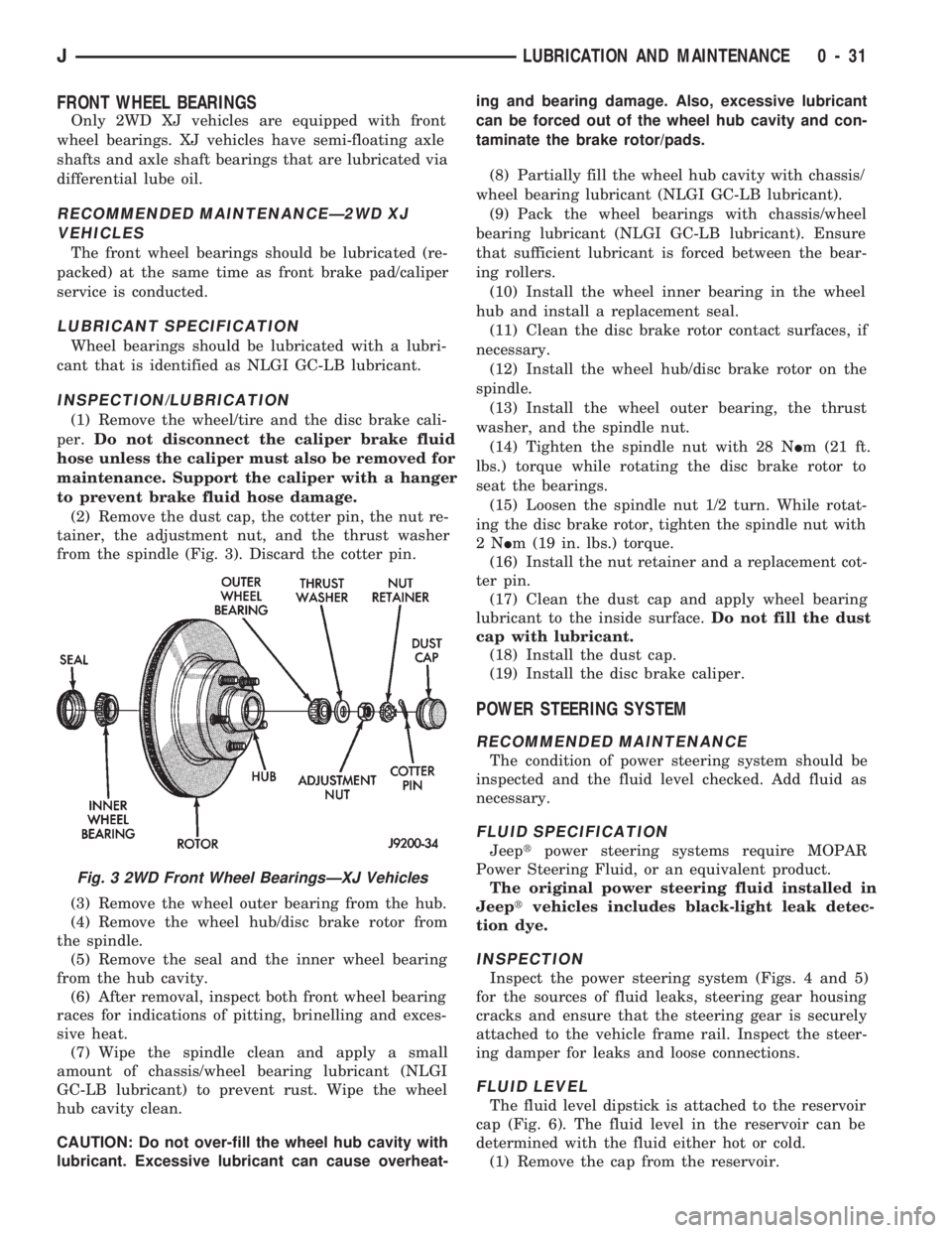
(2) Remove the dust cap, the cotter pin, the nut re-
tainer, the adjustment nut, and the thrust washer
from the spindle (Fig. 3). Discard the cotter pin.
(3) Remove the wheel outer bearing from the hub.
(4) Remove the wheel hub/disc brake rotor from
the spindle.
(5) Remove the seal and the inner wheel bearing
from the hub cavity.
(6) After removal, inspect both front wheel bearing
races for indications of pitting, brinelling and exces-
sive heat.
(7) Wipe the spindle clean and apply a small
amount of chassis/wheel bearing lubricant (NLGI
GC-LB lubricant) to prevent rust. Wipe the wheel
hub cavity clean.
CAUTION: Do not over-fill the wheel hub cavity with
lubricant. Excessive lubricant can cause overheat-ing and bearing damage. Also, excessive lubricant
can be forced out of the wheel hub cavity and con-
taminate the brake rotor/pads.
(8) Partially fill the wheel hub cavity with chassis/
wheel bearing lubricant (NLGI GC-LB lubricant).
(9) Pack the wheel bearings with chassis/wheel
bearing lubricant (NLGI GC-LB lubricant). Ensure
that sufficient lubricant is forced between the bear-
ing rollers.
(10) Install the wheel inner bearing in the wheel
hub and install a replacement seal.
(11) Clean the disc brake rotor contact surfaces, if
necessary.
(12) Install the wheel hub/disc brake rotor on the
spindle.
(13) Install the wheel outer bearing, the thrust
washer, and the spindle nut.
(14) Tighten the spindle nut with 28 NIm (21 ft.
lbs.) torque while rotating the disc brake rotor to
seat the bearings.
(15) Loosen the spindle nut 1/2 turn. While rotat-
ing the disc brake rotor, tighten the spindle nut with
2NIm (19 in. lbs.) torque.
(16) Install the nut retainer and a replacement cot-
ter pin.
(17) Clean the dust cap and apply wheel bearing
lubricant to the inside surface.Do not fill the dust
cap with lubricant.
(18) Install the dust cap.
(19) Install the disc brake caliper.
POWER STEERING SYSTEM
RECOMMENDED MAINTENANCE
The condition of power steering system should be
inspected and the fluid level checked. Add fluid as
necessary.
FLUID SPECIFICATION
Jeeptpower steering systems require MOPAR
Power Steering Fluid, or an equivalent product.
The original power steering fluid installed in
Jeeptvehicles includes black-light leak detec-
tion dye.
INSPECTION
Inspect the power steering system (Figs. 4 and 5)
for the sources of fluid leaks, steering gear housing
cracks and ensure that the steering gear is securely
attached to the vehicle frame rail. Inspect the steer-
ing damper for leaks and loose connections.
FLUID LEVEL
The fluid level dipstick is attached to the reservoir
cap (Fig. 6). The fluid level in the reservoir can be
determined with the fluid either hot or cold.
(1) Remove the cap from the reservoir.
Fig. 3 2WD Front Wheel BearingsÐXJ Vehicles
JLUBRICATION AND MAINTENANCE 0 - 31
Page 34 of 1784
(5) Inspect the reservoir rubber diaphragm seal for
cracks, cuts and distortion.
(6) Inspect the brake fluid tubing fittings and the
master cylinder housing for indications of fluid leak-
age. Repair as necessary.
(7) Install the brake fluid reservoir cover.
ANTI-LOCK BRAKE SYSTEMÐXJ VEHICLES
The anti-lock brake system fluid reservoir for XJ
Vehicles is located in the engine compartment at the
left side of the dash panel.
(1) Turn the ignition switch ON and allow the
pump motor to operate until it automatically de-en-
ergizes.
(2) Clean the cover before removing it.
CAUTION: Over-filling could cause fluid overflow
and possible reservoir damage when the pump mo-
tor energizes.
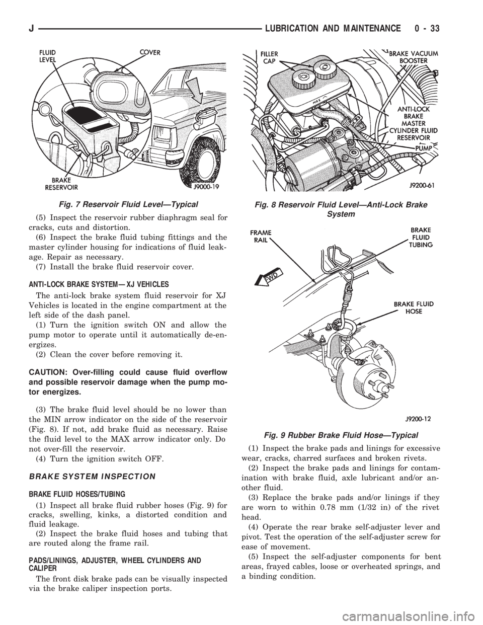
(3) The brake fluid level should be no lower than
the MIN arrow indicator on the side of the reservoir
(Fig. 8). If not, add brake fluid as necessary. Raise
the fluid level to the MAX arrow indicator only. Do
not over-fill the reservoir.
(4) Turn the ignition switch OFF.
BRAKE SYSTEM INSPECTION
BRAKE FLUID HOSES/TUBING
(1) Inspect all brake fluid rubber hoses (Fig. 9) for
cracks, swelling, kinks, a distorted condition and
fluid leakage.
(2) Inspect the brake fluid hoses and tubing that
are routed along the frame rail.
PADS/LININGS, ADJUSTER, WHEEL CYLINDERS AND
CALIPER
The front disk brake pads can be visually inspected
via the brake caliper inspection ports.(1) Inspect the brake pads and linings for excessive
wear, cracks, charred surfaces and broken rivets.
(2) Inspect the brake pads and linings for contam-
ination with brake fluid, axle lubricant and/or an-
other fluid.
(3) Replace the brake pads and/or linings if they
are worn to within 0.78 mm (1/32 in) of the rivet
head.
(4) Operate the rear brake self-adjuster lever and
pivot. Test the operation of the self-adjuster screw for
ease of movement.
(5) Inspect the self-adjuster components for bent
areas, frayed cables, loose or overheated springs, and
a binding condition.
Fig. 7 Reservoir Fluid LevelÐTypicalFig. 8 Reservoir Fluid LevelÐAnti-Lock Brake
System
Fig. 9 Rubber Brake Fluid HoseÐTypical
JLUBRICATION AND MAINTENANCE 0 - 33
Page 35 of 1784
(6) Inspect the disc brake caliper dust boot for cor-
rect installation, damage/tears and indications of
brake fluid leakage. Inspect the bushings and pins
for corrosion, tears and a binding condition.
(7) Pull the rear wheel cylinder dust boot back to
expose the wheel cylinder housing and inspect for
fluid leaks. Inspect the pistons and cylinder bores for
proper appearance.
(8) Inspect the brake differential warning valve
and housing for indications of leakage, kinked hoses
and loose fittings.
PARK BRAKE
(1) As applicable, engage the park brake lever or
pedal and then release it.
(2) If the park brake is functioning normally, test
it for smooth operation and vehicle-holding capabil-
ity.
(3) Inspect the park brake cables for kinks, fraying
and a binding condition.
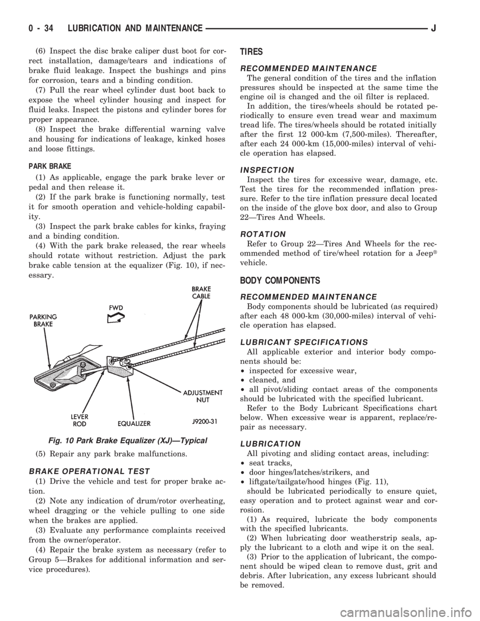
(4) With the park brake released, the rear wheels
should rotate without restriction. Adjust the park
brake cable tension at the equalizer (Fig. 10), if nec-
essary.
(5) Repair any park brake malfunctions.
BRAKE OPERATIONAL TEST
(1) Drive the vehicle and test for proper brake ac-
tion.
(2) Note any indication of drum/rotor overheating,
wheel dragging or the vehicle pulling to one side
when the brakes are applied.
(3) Evaluate any performance complaints received
from the owner/operator.
(4) Repair the brake system as necessary (refer to
Group 5ÐBrakes for additional information and ser-
vice procedures).
TIRES
RECOMMENDED MAINTENANCE
The general condition of the tires and the inflation
pressures should be inspected at the same time the
engine oil is changed and the oil filter is replaced.
In addition, the tires/wheels should be rotated pe-
riodically to ensure even tread wear and maximum
tread life. The tires/wheels should be rotated initially
after the first 12 000-km (7,500-miles). Thereafter,
after each 24 000-km (15,000-miles) interval of vehi-
cle operation has elapsed.
INSPECTION
Inspect the tires for excessive wear, damage, etc.
Test the tires for the recommended inflation pres-
sure. Refer to the tire inflation pressure decal located
on the inside of the glove box door, and also to Group
22ÐTires And Wheels.
ROTATION
Refer to Group 22ÐTires And Wheels for the rec-
ommended method of tire/wheel rotation for a Jeept
vehicle.
BODY COMPONENTS
RECOMMENDED MAINTENANCE
Body components should be lubricated (as required)
after each 48 000-km (30,000-miles) interval of vehi-
cle operation has elapsed.
LUBRICANT SPECIFICATIONS
All applicable exterior and interior body compo-
nents should be:
²inspected for excessive wear,
²cleaned, and
²all pivot/sliding contact areas of the components
should be lubricated with the specified lubricant.
Refer to the Body Lubricant Specifications chart
below. When excessive wear is apparent, replace/re-
pair as necessary.
LUBRICATION
All pivoting and sliding contact areas, including:
²seat tracks,
²door hinges/latches/strikers, and
²liftgate/tailgate/hood hinges (Fig. 11),
should be lubricated periodically to ensure quiet,
easy operation and to protect against wear and cor-
rosion.
(1) As required, lubricate the body components
with the specified lubricants.
(2) When lubricating door weatherstrip seals, ap-
ply the lubricant to a cloth and wipe it on the seal.
(3) Prior to the application of lubricant, the compo-
nent should be wiped clean to remove dust, grit and
debris. After lubrication, any excess lubricant should
be removed.
Fig. 10 Park Brake Equalizer (XJ)ÐTypical
0 - 34 LUBRICATION AND MAINTENANCEJ
Page 38 of 1784
FRONT SUSPENSION AND AXLE
CONTENTS
page page
AXLE NOISE/VIBRATION DIAGNOSIS....... 16
FRONT WHEEL ALIGNMENT............... 5
GENERAL INFORMATION.................. 1
MODEL 30 AXLE AND TUBE AXLE (2WD) . . 20TORQUE SPECIFICATIONS................ 47
XJ FRONT SUSPENSION................. 10
YJ FRONT SUSPENSION................. 13
GENERAL INFORMATION
FRONT SUSPENSION
XJ VEHICLES
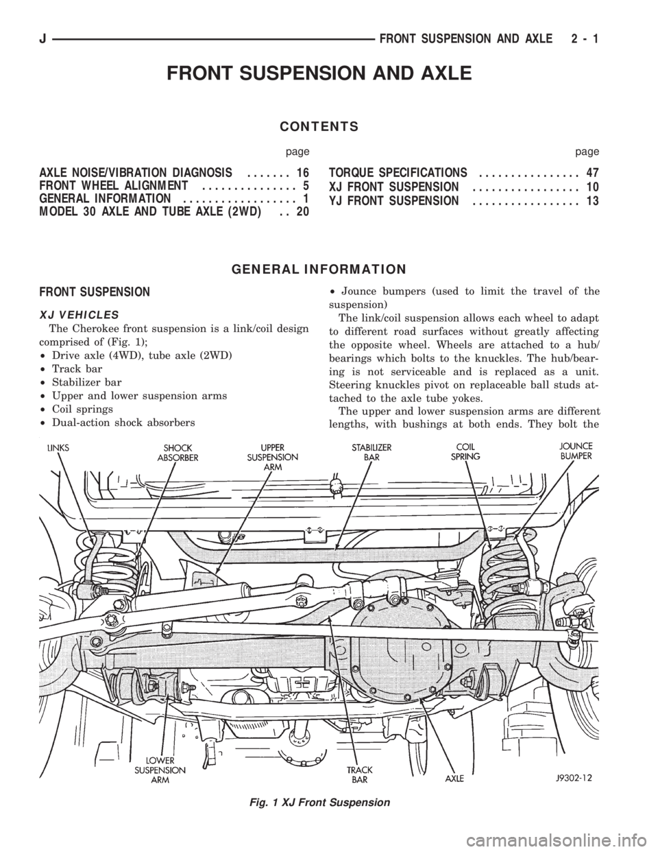
The Cherokee front suspension is a link/coil design
comprised of (Fig. 1);
²Drive axle (4WD), tube axle (2WD)
²Track bar
²Stabilizer bar
²Upper and lower suspension arms
²Coil springs
²Dual-action shock absorbers²Jounce bumpers (used to limit the travel of the
suspension)
The link/coil suspension allows each wheel to adapt
to different road surfaces without greatly affecting
the opposite wheel. Wheels are attached to a hub/
bearings which bolts to the knuckles. The hub/bear-
ing is not serviceable and is replaced as a unit.
Steering knuckles pivot on replaceable ball studs at-
tached to the axle tube yokes.
The upper and lower suspension arms are different
lengths, with bushings at both ends. They bolt the
Fig. 1 XJ Front Suspension
JFRONT SUSPENSION AND AXLE 2 - 1
Page 39 of 1784
axle assembly to the frame. The lower arms uses
shims at the frame mount to allow for adjustment of
caster and pinion angle. The suspension arm travel
(jounce or rebound) is limited through the use of rub-
ber bumpers.
Suspension components which use rubber bushings
should be tightened at vehicle ride height. This will
prevent premature failure of the bushing and main-
tain ride comfort. Bushings must never be lubricated.
The coil springs control ride quality and maintain
proper ride height. The coil springs mount up in the
fender shield which is part of the unitized body
bracket. A rubber isolator is located between the top
of the spring and the frame. The bottom of the spring
seats on a axle pad and is retained with a clip.
The shock absorbers dampen jounce and rebound of
the vehicle over various road conditions. The top of
the shock absorbers are bolted to the frame. The bot-
tom of the shocks are bolted to the axle spring
bracket.
The stabilizer bar is used to minimize vehicle front
sway during turns. The spring steel bar helps to con-
trol the vehicle body in relationship to the suspen-
sion. The bar extends across the front underside of
the chassis and connects to the frame rails. Links are
connected from the bar to the axle brackets. Stabi-
lizer bar mounts are isolated by rubber bushings.
The track bar is used to minimize front axle side-
to-side movement. The bar is attached to a frame rail
bracket with a ball stud and isolated with a bushing
at the axle bracket.
TUBE AXLE (2WD VEHICLES)
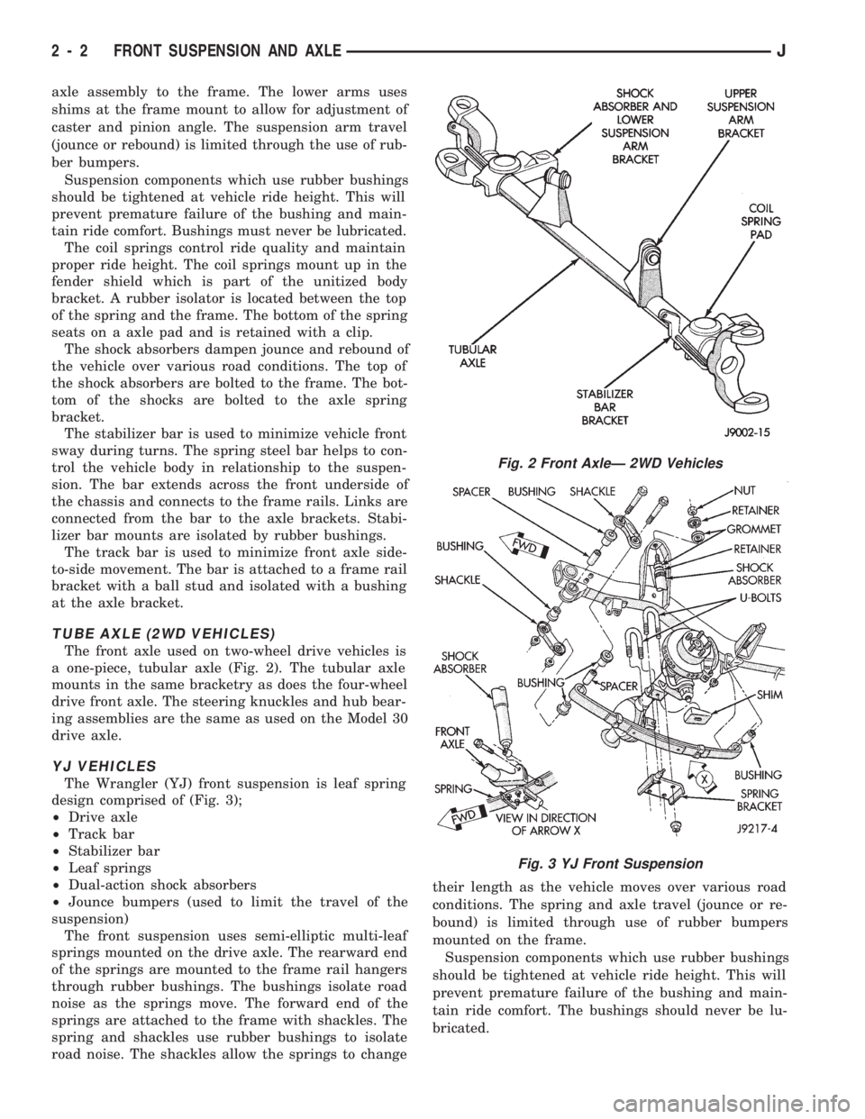
The front axle used on two-wheel drive vehicles is
a one-piece, tubular axle (Fig. 2). The tubular axle
mounts in the same bracketry as does the four-wheel
drive front axle. The steering knuckles and hub bear-
ing assemblies are the same as used on the Model 30
drive axle.
YJ VEHICLES
The Wrangler (YJ) front suspension is leaf spring
design comprised of (Fig. 3);
²Drive axle
²Track bar
²Stabilizer bar
²Leaf springs
²Dual-action shock absorbers
²Jounce bumpers (used to limit the travel of the
suspension)
The front suspension uses semi-elliptic multi-leaf
springs mounted on the drive axle. The rearward end
of the springs are mounted to the frame rail hangers
through rubber bushings. The bushings isolate road
noise as the springs move. The forward end of the
springs are attached to the frame with shackles. The
spring and shackles use rubber bushings to isolate
road noise. The shackles allow the springs to changetheir length as the vehicle moves over various road
conditions. The spring and axle travel (jounce or re-
bound) is limited through use of rubber bumpers
mounted on the frame.
Suspension components which use rubber bushings
should be tightened at vehicle ride height. This will
prevent premature failure of the bushing and main-
tain ride comfort. The bushings should never be lu-
bricated.
Fig. 2 Front AxleÐ 2WD Vehicles
Fig. 3 YJ Front Suspension
2 - 2 FRONT SUSPENSION AND AXLEJ