Page 1336 of 1413

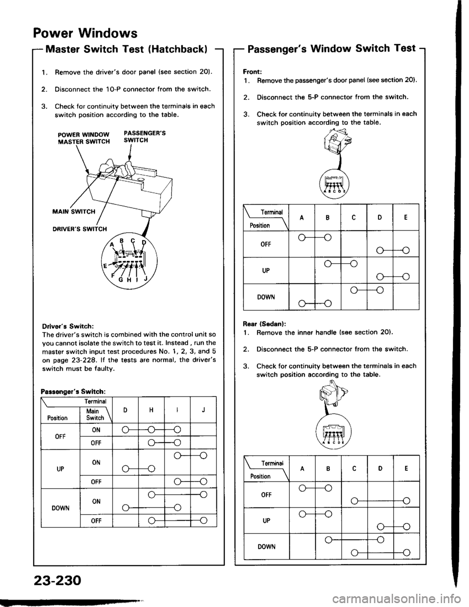
1.Remove the drivef's door panel (see section 201.
Oisconnect the 1O-P connector from the switch.
Check tor continuity between the terminals in each
switch position according to the table.
pOWERWTNDOW PASSENGEB'S
MASTER SWTTCH SWITCH
Drive.'s Switch:
The driver's switch is combined with the control unit so
you cannot isolate the switch to test it. Instead , run the
master switch input test procedures No. 1, 2, 3, and 5
on page 23-228, lf the tests are normal, the d.ivet's
switch must be faultv.
i1\i
\4r-I^l,r
)rvti\
.Fi'ilj
Passengsl'r Switch:
Te.minsl
DHJI Msin \Position I Switch \
OFFONo-(J--o
OFFo--o
UPONo---o
o--
OFFo--o
DOWNONo-
o--o
--o
OFFo--o
Power Windows
Master Switch Test (HatchbacklPassenger's Window Switch Test
23-230
Front:
1 . Remove the passenger's door panel {see section 20).
2. Disconnect the 5-P connector from the switch.
3. Check for continuity between the terminals in each
switch position sccording to the table.
Rear (Sedanl:
1. Remove the inn€r handle (see section 2O)'
2, Disconnect the 5-P connector from the switch.
3. Check for continuity between the terminals in each
switch position according to the table.
Torminal
il;_\
ARD
OFFo-
--o
UPo---o
G_--o
DOWr.lo---o
Terminal
;;__\ID
OFFG_--o
o---o
UPG_--o
o---o
DOWNo---o
o-
Page 1337 of 1413
Master Switch ReplacementPassenger's Window Switch
Hatchback:
1. Remove the driver's door panel (see section 20).
2. Disconnect the 1O-P connector lrom the switch,
3, Remove the three mounting screws and the switch.
Sedan:
1. Remove the driver's door panel (see section 2O).
2. Disconnect the 1 6-P and 1-P connectors from the
switch.
3. Remove the two mounting screws and the switch.
POWER MIRRORswtTcH
scREws
Replacement
Flont:
1 . Remove the passenger's door panel (see section 201.
2. Disconnect the 5-P connector from the switch.
3. Remove the two mounting screws and the switch.
Roar (S6danl:
1. Remove the inner handle (see section 20).
2. Disconnect the 5-P connector from the switch.
3. Remove the two mounting screws and the switch.
w|I{Dow.swtTcH
swtTcl{
INNER HANDLE
23-231
Page 1338 of 1413

Power Windows
Driver's Window MotorTest
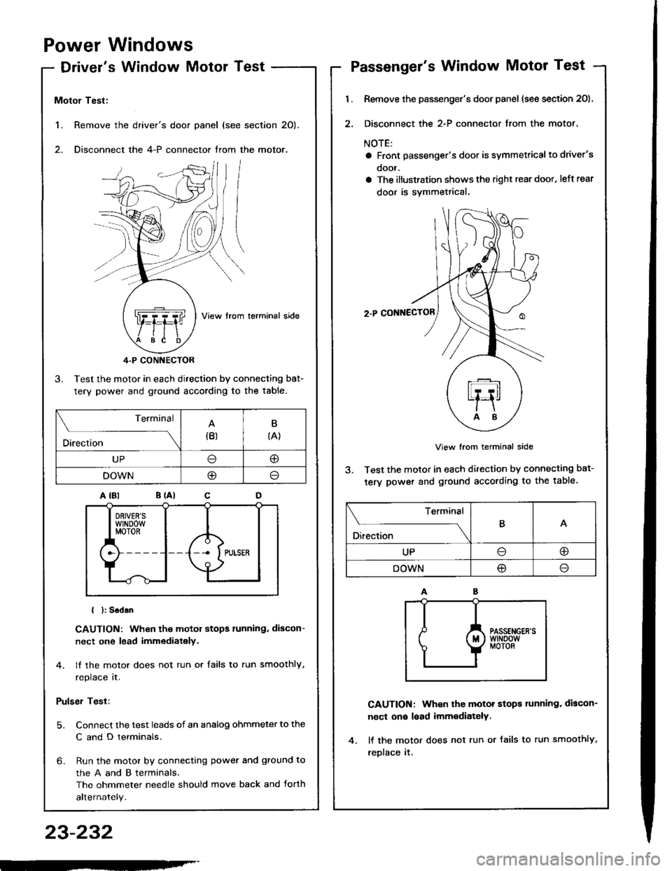
1. Remove the
2. Disconnect
Motor Test:
View from lerminal side
4.P CONNECTOR
3. Test the motor in each direction by connecting bat-
tery power and ground according to the table.
{ }: Sodan
CAUTION: When the motor stops running. discon-
nect one lead immediately.
4. lf the motor does not run or tails to run smoothly,
replace it.
Pulser Test:
5. Connect the test leads of an analog ohmmeter to the
C and D terminals.
6- Run the motor by connecting power and ground to
theAandBterminals,
The ohmmeter needle should move back and torth
alternately.
driver's door panel (see section 20).
the 4-P connector trom the motor.
. ,-,.f,/l l/
NZJI I
..Q]qql ,fiftl I
$e /tE \
Terminal
Direction(B)B
{A}
UP@
DOWNO
Passenger's Window Motor Test
l.
2.
Remove the passenger's door panel (see section 20).
Disconnect the 2-P connector from the motor.
NOTE:
a Front passenger's door is symmetricalto driver's
ooor.
a The illustration shows the right rear doot, left rear
door is svmmetrical.
2.P CONNECTOR
View from terminal side
3. Test the motor in each direction by connecting bat-
tery power and ground according to the table.
CAUTION: When the motor stops tunning. discon-
nect on€ lead imm€diately.
lf the motor does not run or Jails to run smoothly,
reDlace it.
Terminal
O*** \
BA
UPoo
DOWN@
23-232
-'
Page 1360 of 1413
Wipers/Washers
Component Location Index
WII{DSHIELD/REAR WINDOWWIPERAA'ASHEB SWITCHTest, page 23-258Replacement, oase 23 257_..
wtNosHlELD WIPER 2ARMS/BLADES ___-=4,
Repfacemont, Page 23'261 /tt' /
WINOSHIELDIVIPER MOTORTest, page 23-260Repfacement, paee 23-281
FUSE/RELAY BOX
INTERMITTENT WIPERBELAY CIRCUIT(ln the int€gral.d control onitlInput Test, page 23-146
REAR WII{DOW WIPER MOTORTest, page 23-262Replacemont, pago 23-263
23-254
Page 1362 of 1413
Wipers/Washers
Troubleshooting
NOTE: The numbers in the table show the troubleshooting sequence
Item to be insDected
Symptom
i
oo-;i
a.P
:6r!
z)
it
3
o
=
o
E
;
E;
3
E
ID
3
95'6;
>;
eb
rD!otD
;E
cqt
EP
0,(t
i
z
o
=Y.
.9! O
o
t
oo
o
6
i=
.45i5
bE
€3
dOot
Eroc
o
o
o-
o.
:!
-c
oo
Wipers
do not
ln all
positionsI422G301,
G401
GRN/BLK
ln INTI3YEL/BLU,8LU/GRN
In LO or Hl12BLU, BLU/YEL
ln MIST1BLU/YEL
Rear window wiper does
not work.1aG503,
G751
GRN/BLK, GRN
LT GRN/BLK
Blades do not return to
park position when the
switch is turned OFF.
I
BLU/wHT,
LT GRN/BLK
Intermittent cycle is
erratic or wipers do not
work intermiftently.
12
YEL/BLU. BLU/GRN
Little or no washer fluid
is pumped.4?12G301BLK/GRN, BLU/BLK
WiDer snd washer do not
work at the same time.1BLK/GRN
23-256
Page 1365 of 1413
Windshield WiperAi\laEhel Switch
D
EB
R6ar Window Wip€r/Washol Switch
IL
1 o"/j^o-"-'w*+t+*
I-
i' 4l?u l=f,.
_J M|ST M|ST
OFF/INT
Terminal
il;----__\cDEn
OFFo----o
INT
o-
o-*--o
---o
LOG-*-o
HIo---o
Mist switch "ON'G-----o
Washer switch "0N"o----o
II,i1..___.______,x..
fr."ql|.fr tiT
rermrnal
Position \LN
Washer switch "0N"o----oo----o
OFFo--*o
ONo---o
Washer switch "ON"
(with wiDer'0N")o----oo----o
ll lill ili F'
23-259
Page 1368 of 1413
Wipers/Washers
Rear Window Wiper Motor Test-Keal wlnqow wlper |Yloror I esr
1. Disconnect the 4-P connector from the wiper motor.lf the moto. does not run or fails to tun smoothly,
replace it.
Reconnect the 4-P connector to the wipet motor as-
sembly.
Connect an analog voltmeter between the D (LT
GRN/BLKI and B (BLK) terminals. Run the motor by
turning the wiper switch ON.
The voltmeter should slternately indicate O V and
more than 4 V.
NOT€: Use an analog tester.
4.
4-PCONNECTOR
A (GBN/BLK)
C IGRNI
View trom terminal side
2. Test the motor by connecting battery power to the
A (GRN/BLK) and ground to the C (GRN) terminals.
The motor should run smoothly.
C (GRI{}
23-262
Page 1369 of 1413

l.
2.
1.
Rear Window Wiper Motor
Replacement
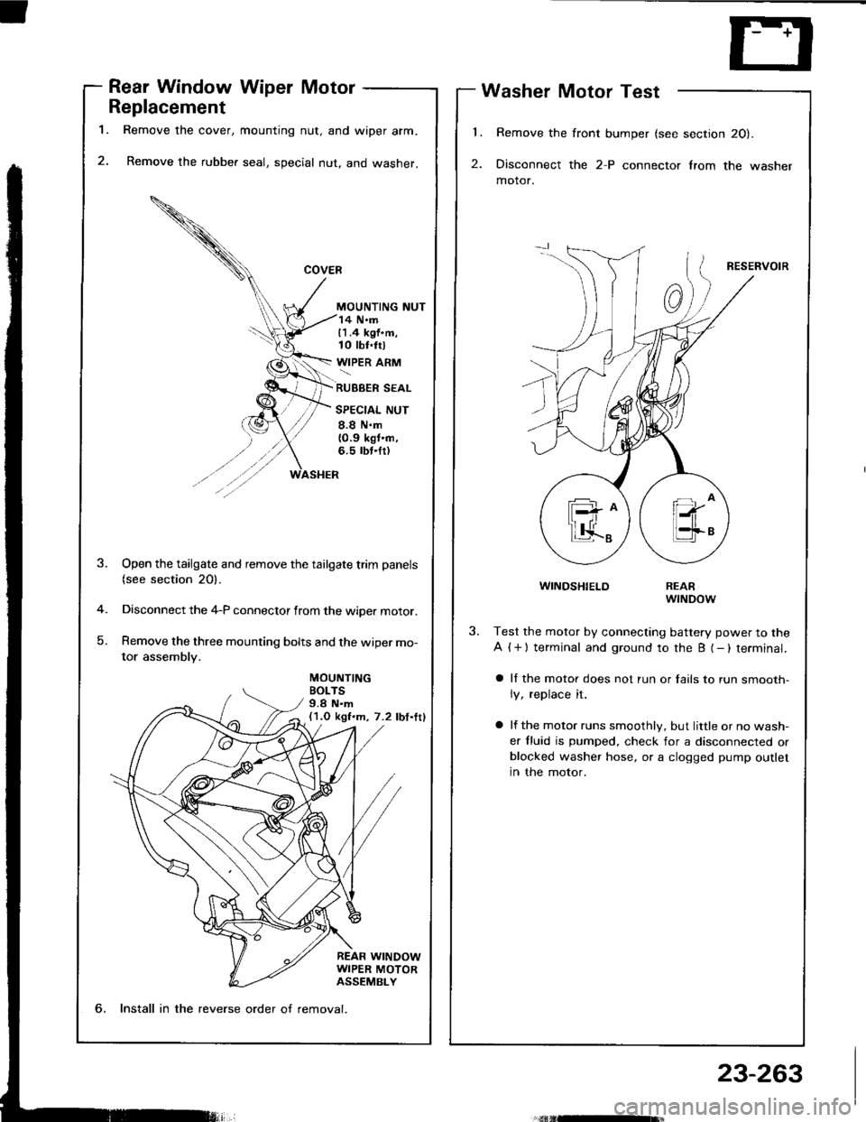
Remove the cover, mounting nut, and wiper arm.
Remove the rubber seal, special nut, and washer.
MOUNTING NUT
Washer Motor Test
Remove the front bumper (see section 20).
Disconnect the 2-P connector lrom the washer
motor.
RESERVOIR
WINDSHIELD
14 N.m11.4 kgf.m,10 tbt.trl
WIPER ARM
RUBBER SEAL
SPECIAL NUT
8.8 N.m{0.9 kgt'n,6.5 rbt.fr)
MOUNTINGBOLTS9.8 N.m(1.O kgf.m, 7.2 lbf.ttl
-4
)
Open the tailgate and remove the tailgate trim panels(see section 20).
Disconnect the 4-P connector from the wiper motor.
Remove the three mounting bolts and the wiper mo-
tor assembly.
REARwrNDow
Test the motor by connecting battery power to the
A ( + ) terminal and ground to the B (- ) terminal.
a ll the motor does not run or fails to run smooth-
ly, replace it.
a lf the motor runs smoothly, but little or no wash-
er fluid is pumped. check for a disconnected orblocked washer hose, or a clogged pump outlet
in the motor.
6, Install in the reverse order o{ removal.
23-263