1994 HONDA INTEGRA ecm connector
[x] Cancel search: ecm connectorPage 463 of 1413
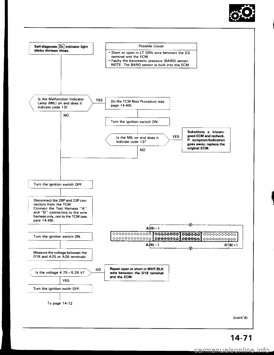
Disconnect lhe 26Pand 22P con-nectors trom the TCMConnect the Test Hahess "A"
and "D" connectors to the wireharness only, not to th€ TCM {seepare'14-49).
Possible Cause
. Short or open in LT GRN wire between the D3terminal and the ECM.. Fauky the barometric pressure {8ARO} sensor.NOTE: The BARO sensor is built into lhe ECM.
ooooooooooooo
oooooooooooo0oOOqgopg I,oiOOOOol ooo ooooooooooocqooo:Joo.oipggl o oooooo o 9ooTurn the ignition swirch ON.
Measure the voltage between theD18 and A25 or A26 terminals.
ls the voltage 4.75-5.25 V?
Turn the ignition swith OFF.
A25t- |
Soll-diagnosis Lq! indicator lightblinks thirtoon tim6.
ls rhe Malfunction lndicatorLamp (MlL) on and does itindicate code 13?
Do the TCM Rest Procedure (seepage 14-49).
Turn the ignition switch ON.
Substituto a known-good ECM and rechock.ll symptom/lndicationgoos away, .oplace theoriginal ECM.
ls the MIL on and does itindicare code 13?
Turn the ignition switch OFF.
Ropair opon or short in WHT/BLKwir6 botwoon th€ D18 to.minaland tho EcM.
fo page 14-72
14-71
Page 464 of 1413

Electrical Troubleshootang
Troubleshooting Flowchart (cont'd)
From page '14-71
TCM 22P CONNECTOR
Disconnect the 22P connectorslrom the TCM and ECM.
Check for continuity between theD3 {LT GRN) terminal ol the TcM22P connecror and the D8 ILTGRN) terminal of the ECM 22Pconnector.
Ropai. opon In LT GRN rvi.a b.-twoon tho TCM and ECM.
Check lor continuity between theLT GRN wire and body ground.
Ropair short lo body ground inLT GRN wir6.
Ch€ck lor loos6 TCM and ECMconnectors, lf necessary, aubari-tute a known-good TCM andrccheck.
NOTE: View from wire side.
ECM 22P COiINECTOR
14-72
Page 466 of 1413

Electrical Troubleshooting
Troubleshooting Flowchart (cont'd)
ls there continuity?
o o o o o o o o O o O o O $:O.COOtt9O$:l:OtO:CtOiOi:l O o O O O O o O o o Oo o o o o o o o o o o o O I:f(O.{iltltO{t{t:I:OFA:F:d:O:l o o o o o o o O o o o
NOTE: View lrom wire side.
NO
From page 14-73
Measure the voltage between theD 16{+ ) and A25 or A26{- ) ter-mtnals.
Check for loos€ TCM connoctors.ll ngcossary, substituto a known-good TCM and rechock.
ls there approx. 5 V?
Disconnect the 26P connectorfrom the ECM.
Check for continuitv between theD16 and A25 or A26 rerminals ofthe Test Harness.
Ropairshort in YEL IFAS) wire be-tw6on TCM and ECM.
Disconnect the 26P and 22P con-nectors from the Test Harness.
Check for continuity between theD16 (YEL) terminal ot fCM 22Pconnector and A19 (YEL) terminalof ECM 26P connector.
Chgck tor loos€ TCM connoctofs.lf nocassary, substitute o known-good TCM and rech6ck.
Ropair opon in YEL {FAS} wiro bo-trve€n TCM and ECM.
oooooooooooo
oooooooooooo
ooooooooooo
ooooooooooo
22P CONNECTOB
Page 482 of 1413
![HONDA INTEGRA 1994 4.G Workshop Manual Road Test
NOTE: Warm up the engine to operating temperature (the cooling fan comes on).
1 Apply parking brake and block th€ wheels. Start the engine, them move the selector lever to E] position whil HONDA INTEGRA 1994 4.G Workshop Manual Road Test
NOTE: Warm up the engine to operating temperature (the cooling fan comes on).
1 Apply parking brake and block th€ wheels. Start the engine, them move the selector lever to E] position whil](/manual-img/13/6067/w960_6067-481.png)
Road Test
NOTE: Warm up the engine to operating temperature (the cooling fan comes on).
1 Apply parking brake and block th€ wheels. Start the engine, them move the selector lever to E] position whiledepressing the brake pedal. Depress the accelerator pedal, and release it suddenly. The engine should not stall,
2. Repeat same test in @ position.
3. Shift the selecto. lever to E position, and chock that the shift points occur at approximate speeds shown. Alsocheck fof abnormal noise and clutch slippage.
NOTE: Throttle position sensor voltage fepresents the throttle opening.
- 1 . Connect the Test Harness between the ECM and connector (see section 1 1).-2. Setthe digital multimeter to check voltage between D1 1{+)terminal and D22 { - ) terminal for the throttle Dosi-tion sensor.
TESTHARI{ESSOTLAJ_PT3OlOA
DIGITAL MULTIMETERCommarcially avsilablo o.KS-AHM-32-OO3
011 {+oooooooooooooooooooooooooooooooooooooooooooooooooooooooooooooooooooooooooooo
14-90
Page 1130 of 1413
Connector ldentification and Wire Harness Routing
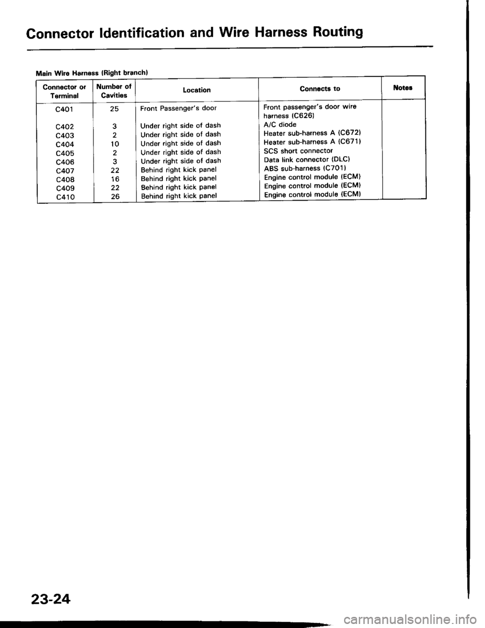
Main Wire Ha.ness {Right branch}
Connactor or
Terminal
Numbsr of
Caviti€sLocationConnscts tottlotor
c401
c402
c403
c404
c405
c406
c407
c408
c409
c410
,E
10
2
22
lo
22
26
Front Passenger's door
Under right side of dash
Under right side ot dash
Under right side of dash
Under right side of dash
Under right side ot dash
Behind right kick panel
Behind right kick panel
Behind right kick panel
Behind right kick panel
Front passenger's door wire
harness (C626)
A/C diode
Heater sub-harness A (C672)
Heater sub-harness A {C671}
SCS short connectol
Data link connector (DLC)
ABS sub-harness (C7011
Engine control module (ECM)
Engine control module (ECM)
Engine control module (ECMI
23-24
Page 1182 of 1413
Starting System
Startel Test
NOTE: The air temDerature must be between 59 8nd
10OoF (15 and 38oC) before testing.
Recommendsd Procodure:
a Use a staner svstem tester.
a Connect and operate the equipment in accordance
with the manutacturer's instructions.
a Test and troubleshoot as described.
Altohato Procedure:
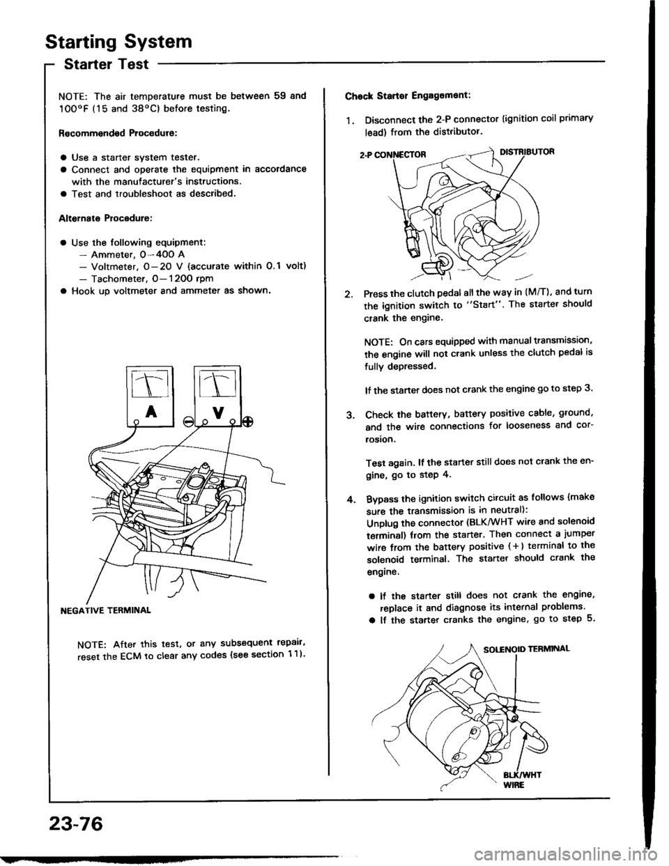
a Use the following equipment:- Ammeter. 0-4OO A- Voltmeter, O- 20 V {accurate within 0.1 volt)
- Tachometer, O- 120O rpm
a Hook up voltmeter and ammeter as shown'
NEGATIVE TERMINAL
NOTE: After this test, or any subsequent repair,
reset the ECM to clear any codes (see section 1 1)
23-76
2.
Chock Stan€r Engag6ment:
1. Disconnect the 2-P connector (ignition coil primary
lead) from the distributor.
Press the clutch pedal allthe way in (M/T), and turn
the ignition switch to "Start". The starter should
crank the engine.
NOTE: On cars equipped with manual transmission,
the engine will not crank unless the clutch pedal is
fully depressed.
lf the staner does not crank the engine go to step 3.
Check the baftery, battery positive cable, ground,
and the wire connections for looseness and cor-
rosion,
Test again. lf the starter still does not crank the en-
gine, go to step 4.
Bvpass the ignition switch citcuit as follows {make
sure the transmission is in neutral):
Unplug the connector (BLK/WHT wire and solenoid
terminsl) trom the starter. Then connect a jumper
wire from the battery positive ( + ) terminal to the
solenoid terminal. The starter should crank the
engrne.
a lf the starter still does not crank the engine,
replace it and diagnose its internal problems.
a lf the starter cranks the engine, go to step 5.
J.
4.
Page 1241 of 1413
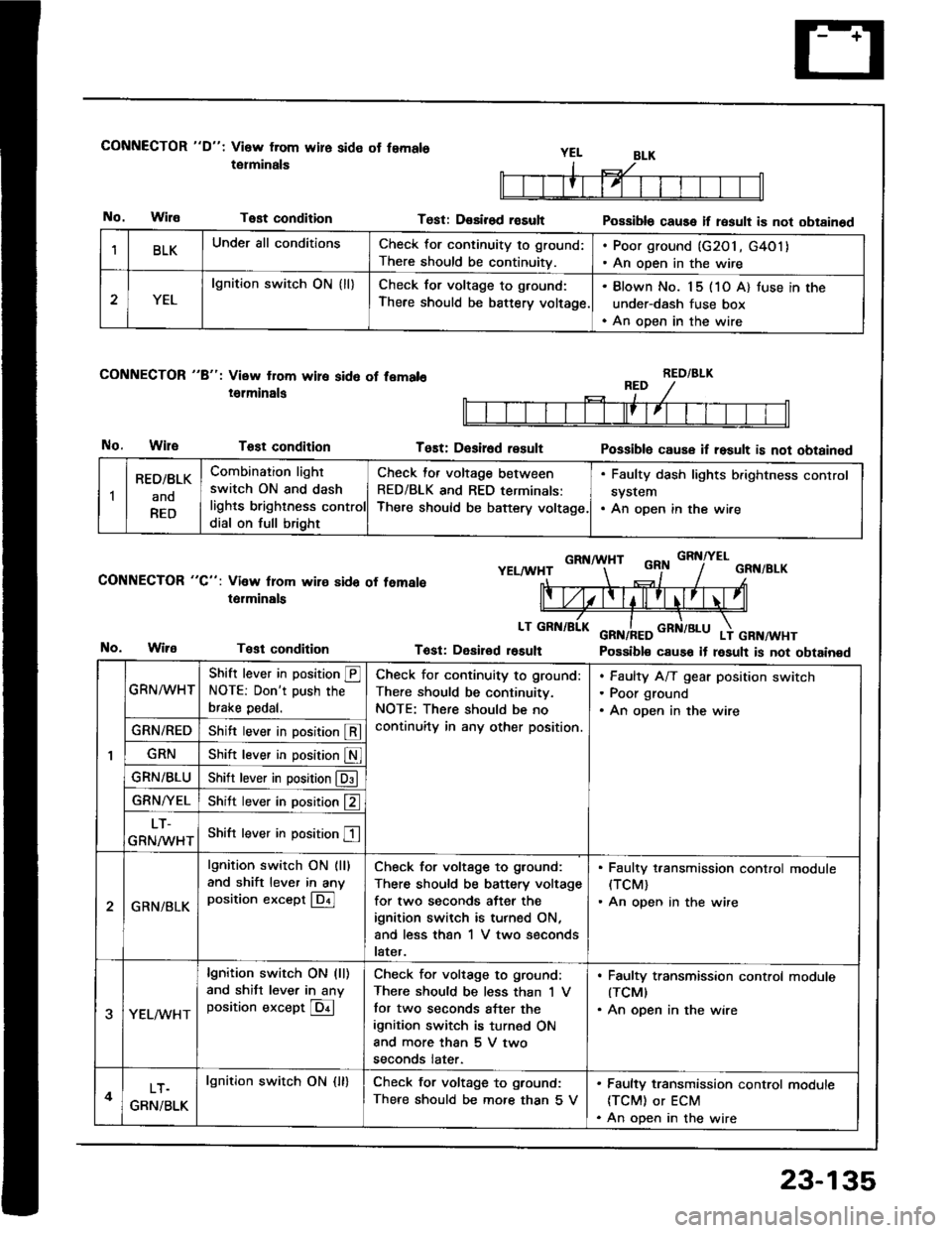
CONNECTOR "D": Visw from wire side ot femals
tetminals
No.WilaTest condition
CONNECTOR "8": View from wire sid6 of fem.l6
i6lminals
No.WileTost condition
CONNECTOR "C": Vi3w lrom wire sido of temale
t6rminals
Test condition
Test: D€sirod rasultPossible cause if result is not obtainod
Tost: D€sir6d resultPossiblo cause if result is not obtained
GRNA HTGRNITELYELAA'HTGRN/BLK
Tost: Desirod r6sult Possible cause it result is not obtainedNo.
BLKUnder all conditionsCheck for continuity to ground:
There should be continuitv.
. Poor ground (G2O1, G4O1). An open in the wire
2YEL
lgnition switch ON { ll}Check for voltage to ground:
There should be battery voltage.
. Blown No. 15 (1O A) tuse in the
under-dash fuse box. An open in the wire
RED/BLK
1
RED/BLK
ano
RED
Combination light
switch ON and dash
lights brighlness control
dial on full bright
Check for voltage between
RED/BLK and RED terminals:
There should be baftery voltage.
. Faulty dash lights b.ightness control
system. An open in the wire
GRN^^/HT
Shift lever in position @NOTE: Don't push the
brake pedal.
Check for continuity to ground:
There should be continuitv.
NOTE: There should be no
continuity in any other position.
Faulty A/T gear position switch
Poor ground
An open in the wire
GRN/REDShift lever in position @
GRNShift lever in position S
GRN/BLUShitr lever in position @
GRN/YELShitt lever in position f2 ]
LT-
GRNMHTShift lever in position E
2GRN/BLK
lgnition switch ON (ll)
and shift lever in anyposition except @
Check for voltage to ground:
There should be battery voltage
for two seconds after the
ignition switch is turned ON,
and less than 1 V two seconds
later.
. Faulty t,ansmission control module(TCM)
. An open in the wire
3YEL/vVHT
lgnition switch ON (ll)
and shitt lever in anyposition except @
Check for voltage to ground:
There should be less than 'l V
tor two seconds after the
ignition switch is turned ON
and more than 5 V two
seconds later.
. Faulty transmission control modute(TCMI
. An open in the wire
4LT.
GRN/BLK
lgnition swirch ON {ll}Check for voltage to ground:
There should be mofe than 5 V
. Faulty transmission control module
ITCM) or ECM. An open in the wire
23-135
Page 1247 of 1413
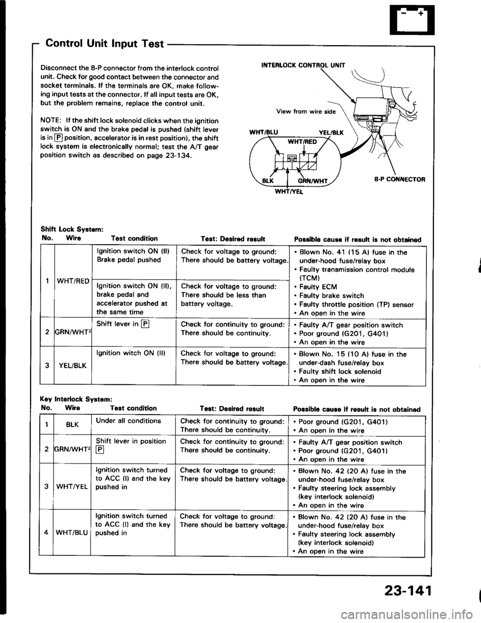
Control Unit Input Test
Oisconnect the 8-P connector from the interlock control
unit. Check for good contact between the connector and
socket terminals. lf the terminals 8re OK, make Iollow-
ing input tests at the connector. lf all input tests are OK,
but the problem remains, replace the cont.ol unit,
NOTE: lf the shilt lock solenoid clicks when the ignition
switch is ON and the brake pedal is pushed (shift tever
is in lfl position, accelerator is in rest position), the shiftlock system is electronically normal; test the A/T gear
positaon switch as described on page 23- 134.
Shift Lock Sy.tem:
No, Wlr6 Tost condition
Koy Intodock Systam:
No. WireT6st condition
Tost: Dosired resultPossiblo cause if rssuh is not obtainod
T6st: Desiled reaultPossible caure if rosult is not obtainsd
'I
lgnition switch ON (ll)
Brake pedal pushedCheck for voltage to ground:
There should be bsttery voltage
Blown No. 41 (15 A) fuse in the
under-hood fuse/relay box
Faulty transmission control module(TCM}
Faulty ECM
Faultv brake switch
Faulty throftle position lTP) sensor
An oDen in the wire
wn t/hEulgnition switch ON
brske pedal and
accelerator pushed
the same time
I [),
at
Check for voltage to ground:
There should be less than
battery voltage.
GRN^/vHT'
Shift lever in @Check lol continuity to ground:
There should be continuity.
Faulty A/T gear position switch
Poor ground {G201, G401}
An oDen in the wire
YEL/BLK
lgnition witch ON (lllCheck for voltage to ground:
There should be battery voltage
Blown No. 15 (10 A) luse in the
under-dash fuse/relay box
Faulty shift lock solenoid
An oDen in the wire
BLKUnder all conditionsCheck for continuity to ground:
There should be continuitv.
. Poor ground (G2O1, G4O1). An ooen in the wire
2
Shift lever in position
E
Check for continuity to ground;
Ther€ should be continuity.
Faulty A/T gear position swirch
Poor ground (c2O1 , G4O1)
An oDen in the wire
3WHTAYEL
lgnition switch tu.ned
to ACC (ll 8nd the keypushed in
Check for voltage to ground:
There should be battery voltage
Bfown No. 42 l2O Al fuse in the
under-hood tuse/relay box
Faulty steering lock assembly(kev interlock solonoid)
An oDen in the wire
4WHT/BLU
lgnition switch turned
to ACC (ll and the keypushed in
Check tor voltage to ground:
There should be batery voltage,
Bfown No. 42 l2O Al fuse in the
under-hood fuse/relav box
Faulty steering lock assembly(key interlock solenoid)
An oDen in the wire
23-141