1994 HONDA INTEGRA Mainshaft
[x] Cancel search: MainshaftPage 430 of 1413

Description
Lock-up System
Lock-up Clutch
1. Operation (clutch on)
With the lock-up clutch on, the oil in the chamber between the torque convener cover and lock-up piston is discharged,and the converter oil exerts pressure through the piston against the converter cover. As a result, the converter turbineis locked on the converter cover firmly. The etfect is to bypass the converter, thereby placing the car in direct drive.
tpowefJlo-wl
The power tlows by way of:
Engine
I
Drive plate
I
Torque convener cover
I
Lock-up piston
I
Damper spring
I
Turbine
t
Mainshaft
TOROUE CONVERTERCOVER
LOCK-UP
TURBINE
To oil cooler
2. Operation (clutch off)
With the lock-up clutch off, the oil tlows in the reverse of CLUTCH ON. As a result, the lock-up piston is moved away
from the converter cover; that is, the torque converter lock-up is released.
Fowtttowl
Engine
I
Drive plate
I
Torque converter cover
Pump
I
Turbine
I
Mainshaft
OUTLET
t
,\
TURBINE
14-38
Page 431 of 1413

In E position in 2nd, 3rd and 4th, and @ position in 3rd, pressurized fluid is drained from the back of the torque con-
verter through an oil passage, causing the lock-up piston to be held against the torque converter cover. As this takes
place, the mainshaft rotates at the same speed as the engine crankshaft. Together with hydraulic control, the TCM op-
timized the timing ot the lock-up system. Under certain conditions, the lock-up clutch is applied during deceleration, in
3rd and 4th sDeed.
The lock-up system controls the range of lock-up according to lock-up control solenoid valves A and B, and throttle valve B.
When lock-up control solenoid valves A and B activate. modulator pressure changes. Lock-up control solenoid valves
A and B are mounted on the torque converter housing, and are controlled by the TCM.
NOTE:
When used, "left" or " tight" indicates direction on the tlowchart.
LOCK IJP COIITBOL
Solenoid valve
L""f."p "."aiti""\B
Lock-up OFFOFFOFF
Lock-up, slightONOFF
Lock-up, halfONON
Lock-up. fullONON
Lock-up
during decelerationONDuty operation
OFF -ON
LOCI( UP TIMII{G B VAIVE
{cont'd)
ott coot€R
14-39
Page 437 of 1413

Component Location
)/
,/s\
{7v
A0t
AUTOMATIC TRANSAXLE IA/TIGEAR POSITION SWITCH
VEHICLE SPEEDSENSOR {VSSI
COUNTERSHAFTSPEED SEf{SORMAINSHAFT SPEEDSENSORTHROTTLE POSITION (TP}SENSOR
at
,
)''ENGINE COOLANT TEMPERATURE (ECTISENSOR
14-45
Page 443 of 1413

Number of @indicator light
blinks while
Service Check
Connector is
connected with
the special tool.
@ indicator
lightPossible CauseSymptomRefer to
page
'loBlinksDisconnected engine coolant tempera-
rure (ECT) sensor connector
Short or open in ECT sensor wire
Faulty ECT sensor
Lock-up clutch does not
engage.14-68
1lOFFDisconnected ignition coil connector
Short or open in ignition coil wire
Faulty ignition coil
. Lock-up clutch does not
engage.'t 4-7 0
13Blinks. Shon or open in LT GRN wire between
the D3 terminal and ECM. Faulty barometric pressure {BARO)
sensor
NOTE: The BARO sensor is built into
the ECM
. No specific symptom
appears.
14-7 1
14Blinks. Short of open in FAS {YEL} wire be-
tween the D16 terminal and ECM. Faulty ECM
. Transmission jerks hard
when shitting.
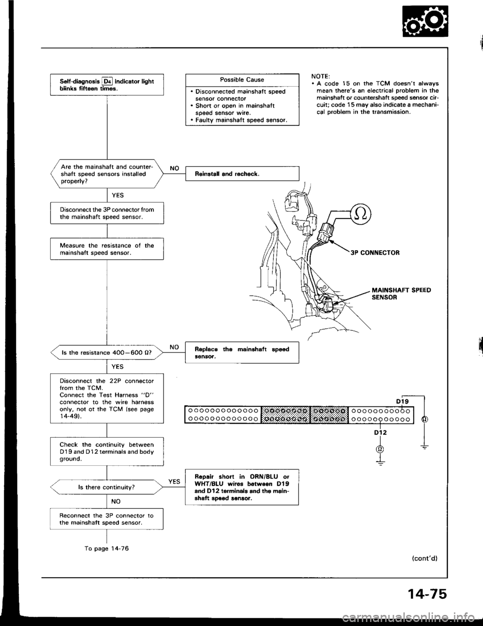
't5OFFDisconnected mainshaft speed sensor
connecror
Short or open in mainshaft speed sen-
sor wire
Faulty mainshaft speed sensor
. Transmission jerks hard
when shifting.
14-75
SymptomProbable CauseRet.page
LQ! indicator light is on steady, not blinking whenever the ignition is on.14-77
[Q3] indicator light does not come on for 2 seconds after ignition is first
turned on.14-78
Lock-up clutch does not have duty operation (ON-OFFI.Check A/C signal with
A/C on.14-80Lock-up clutch does not engage.
Shitt leve. cannot be moved lrom @ position with the brake pedal
depressed.Check brake switch signal,14-41
It the self-diagnosis LQ4 indicator light does not blink, perform an inspection according to the table below.
a lf a customer describes the symptoms for codes 3, (yet the LQ! indicator light is not blinkingl, 6, 1 1 or 15, it will
be necessa.y to recreate the symptom by test driving. and then checking the @ indicator light with the ignition still
oN.
e lt ttre @ indicator light displays codes olher than those listed above or stays lit continuously, the TCM is faulty.. Sometimes the Lqd indicator light and the Malfunction Indicator Lamp (MlL)/Check Engine light may come on simul-taneously. lf so, check the PGM-Fl system according to the numbe. of blinks on the MIL/Check Engine light. thenreset the memory by removing the BACK UP fuse in the unde.-hood fuse/relay box for more than 1O seconds. Drive
the vehicle for several minutes at speed over 30 mph (5O km/h), then recheck the MIL/Check Engine light.
NOTE:
. PGM-FI system
The PGM-Fl system on this model is a sequential multiport fuel injection system.a Disconnecting the BACK UP luse also cancels the radio anti-theft code. preset stations and the clock setting. Get
the fuse so vou can reset them.the customer's code number and make note ot the radio
14-51
Page 467 of 1413

Possible Cause
. Disconnected mainshaft speedsensor connecror. Short or open in mainshaltspeed sensor wrre.. Faulty mainshatt speed sensor.
NOTE:. A code 15 on the TCM doesn't alwsysmean there's an electrical problem in themainshaft or countershaft speed sensor cir-cuit; code '15 may also indicate a mechani-cal Droblem in the transmission.
3P CONNECTOR
II o o o o o o o oo o o o o I:OtlO$O$g:Sl!:OlXOl*Ofill o o o o o o o o o O o | |
I ooooooooooooo l Sciii:ddii:ijii:l:i$idi$;d6#:l o oooop oo ooo | 6
"-f
1-L(0)Y-!
(cont'd)
solf-diagnosis E indicator lightblink tiftoon timos.
Are the mainshaft and counter-shalt speed sensors installedproperly?
Disconnect the 3P connector lromthe mainshaft speed sensor.
Measure the resistance ot themainshaft speed sensor.
ls the resistance 4OO-600 O?
Disconnect the 22P connectorfrom the TCM.Connect the Test Harness "D"
conneclor to the wire harnessonly, not ot the TCM (see page14-49).
Check the continuity betweenD19 and D12 terminals and bodyground.
Rcoair short in ORN/BLU otWHT/BLU wiros botween Dlgand Dl2 to.minals and tho main-shatt speod ronsor.
Reconnect the 3P connector tothe mainshatt speed sensor,
To page 14-76
14-75
Page 468 of 1413

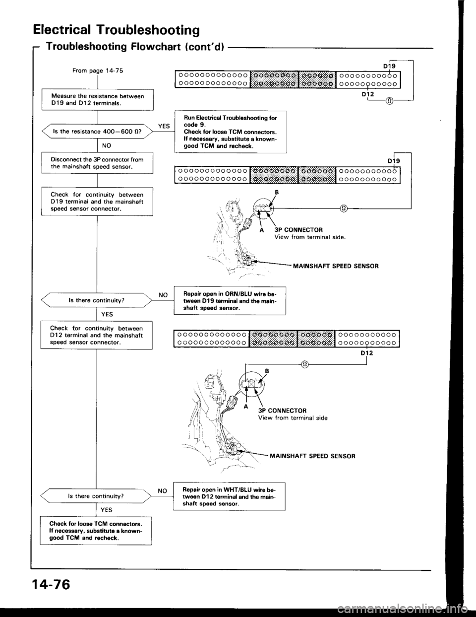
Electrical Troubleshooting
Troubleshooting Flowchalt (cont'd)
From page 14-75ooooooooooooo
oooooooooooooooooooooooo
ooooooooooo
Measure the resistance betweenD19 and D12 terminals.
Run Electrical Troubleshooting folcode 9.Check for loos6 TCM connectors.It nocessary, substitute a known-good TCM and r.check.
ls the resistance 4O0-600 0?
Disconnecl the 3P connector fromthe mainshaft speed sensor.
Check tor continuitv betweenD19 terminal and the mainshaltspeed sensot connector.
Ropair op.n in ORN/BLU wir6 b6-tweon D19 terminal snd th€ main'shaft spa6d sensor.
Chock tgr continuity betweenD12 terminal and the mainshattspeed sensor connector.
Ropair open in WHT/BLU wire be-twe€n D12 tgrminal and th€ main-shaft sD6ed sonsor.
Chsck for loos€ TCM connoctors.ll noco$ary, substitute a known-good TCM and rocheck.
ooooooooooooo
ooooooooooooooooooooooo
ooooooooooo
ooooooooooooo
ooooooooooooo
ooooooooooo
ooooooooooo
MAINSHAFT SPEED SENSOR
3P CONNECTORView from terminal side
MAINSHAFT SPEED SENSOR
14-76
Page 477 of 1413

Mainshaft/Countershaft
Speed Sensors
Replacement
Disconnect the speed sensor connectors, then re-
move the harness clamp on the countershatt speed
sensor harness from the harness stay.
Remove the 6 mm bolts securing the mainshaft and
countershalt speed sensors from the transmission
housrng.
Remove the mainshaft and countershaft speed
sensors,
Installthe mainshatt and countershalt speed sensors
in the reverse order of the removal.
COUNTERSHAFTSPEED SENSOR
I{ARNESS STAY
6 x'l,O mml2 N.m{1.2 kgf.m,8.7 tbf.fr)
6 x 1.O mm12 N.m(1.2 kgf.m,8.7 tbf.ltl
14-85
Page 481 of 1413

NOTES
A.See flushing procedure, page l4-168 and 169.
B.Set idle rpm in gear to specitied idle speed. lf still no good, adiust motor mounts as outlined in engine
section of service manual.
lf the large clutch piston O-ring is broken, inspect the piston groove for rough machining.
lf the clutch pack is seized or is excessively worn, inspect the other clutches Jor wear, and check the
orifice control valves and throttle valves for free movement.
E.It throttle valve B is stuck, inspect the clutches for wear.
lf the 1-2 shift valve is stuck closed, the transmission will not upshift. lI stuck open, the transmission
has no lst gear.
H.lf the 2-3 orifice control valve is stuck, inspect the 2nd and 3rd clutch packs for wear.
ll the orifice cont.ol valve is stuck, inspect the 3rd and 4th clutch packs for wear.
lf the clutch Dressure control valve is stuck closed, the transmission will not shilt out of 1st gear.
K.improper alignment or main valve body and torque converter housing may cause oil pump seizure. The
symptoms ale mostly an rpm-related ticking noise or a high-pitched squeak.
L.ll the ATF strainer is ctogged with panicles of steel or aluminum, inspect the oil pump and ditferential
pinion shaft. lt both are OK and no cause lor the contamination is found, replace the torque converter.
M.lf the 1st clutch feedpipe guide in the right side cover is scored by the mainshaft, inspect the ball bear-
ing for excessive movement in the transmission housing. lf OK. replace the right side cover as it is dent-
ed. The O-ring under the guide is probably worn.
N.ReDlace the mainshstt if the bushing for the 4th feedpipe is loose or damaged.
It the 4th feedpipe is damaged or out ot tound, replace the right side cover'
Replace the subjshaft it thtbushing for the 1st-hold Jeedpipe is loose or damaged.
lf the 1st-hold feedpipe is damaged or out of round, replace it.
Replace the mainshaft if the bushing lor the 1st feedpipe is loose or damaged.
lf the lst feedpipe is damaged or out ot round, replace it.
o.A *o- r, da."s"d "p-g clutch is mostly a result of shifting the transmission in El or Lq! position
while the wheels rotate in reverse, such as rocking the car in snow.
P.InsDect the frame for collision damage.
o.Inspect for damage or wear:
1. Reverse selector gear teeth chamfers.
2. Engagement teeth chamters of countershaft 4th and reverse gear.
3. Shift fork for scutt marks in center.
4. Differential Dinion shaJt for wear under pinion gears.
5. Bottom of 3rd clutch for switl marks.
Replace items 1 , 2, 3 and 4 it worn or damaged. lf transmission makes clicking, grinding or.whirring
noise, atso replace mainshaft 4th gear and reverse idler gear and countershaft 4th gear in addition to
1,2,3ot4.lf ditiersntial Dinion shaft is worn, overhaul differential assembly, and replace ATF strainel, and thoroughly
clean transmission, tlush torque convertet, cooler and lines.
lf bottom of 3rd clutch is swirled and transmission makes gear noise, replace the countershaft and tinal
driven gear.
R.Be wry careful not to dsmage the torque converter housing when replacing the main ballbearing. You
may al;o damage the oil pump when you torque down the main valve body. This will result in oil pump
seizure it not detected. Use proper tools.
qInstall the main seal tlush with the torque converter housing, lf you push it into the torque converter
housing until it bottoms out. it will block the oil return passage and result in damage.
T,Harsh do\/vnshiJt"\./l,'hen coasting to a stop with zero th.ottle may be caused by a bent-in throttle valve
retainer/cam stopper. Throttle cable adjustment may clear this problem.
ifuitle cable adjustment is essential for proper operation of the transmission. Not only does it affect
the shift points if misad,usted, but also the shift quality and lock-up clutch operation'
A cable adjusted too long will result in throttle pressure being too low for the amount of engine torque
input into ihe trsnsmission and may cause clutch slippage. A cable adjusted too short will result in too
hi;h throttle pressure which may cause harsh shitts, erratic shrfts and torque con
14-89