1994 HONDA INTEGRA emission
[x] Cancel search: emissionPage 323 of 1413

Emission Control System
Positive Crankcase Ventilation (PCVI System
Description
The Positive Crankcase Ventilation (PCV) system is
designed to prevent blow-by gas {rom escaping to the
atmosphsre. The PCV valve contains a spring-loadsd
plunger. When the Bngine starts, the plunger in the PCV
valve is lifted in proportion to intake manifold vacuum
and the blow-by gas is drawn directly into th€ intak€
manifold.
FCV VALVE
.F: ILOW-BY VAFORer FRESH AIR
11-134
Insp€cdon
1. Check th€ PCV hos6s and connections tor lsaks and
clogging.
At idle, mak6 sur€ th6fe is a clicking sound from th6
PCV valve when the hose between rcV valve and
intake manifold in lightly pinched with your fingors
or oli€rs.
a lf thera is no clicking sound, ch6ck the PCV valve
grommet for cracks or damage. ll the grommet
is OK, reolace the PCV valve and recheck.
2.
SREATHER
Gontly pinch hero.
Page 324 of 1413

A.
Evaporative Emission (EVAPI Controls
Da.cdptlon
Thg avaporstive omission controls are designed to minimize the smount of fusl vapor escaping to the atmosphero. The
system conaists ot the following compon€nts:
Evlporttly. Emlttbn (EVAPI Control Caniltot
An EVAP control canistor is used lor the temporary storage ot fuel vapor until the fuel vapor can be purged lrom
th€ EVAP control canister into the engin€ and burned.
vlpor hr]gG Cmt]ol Syst m
€VAp control canistgr puroing is accomplished by drawing fresh air through tho EVAP control canister and into a
pon on th6 throttl€ body. Th€ purging vacuum is controllsd by the EVAP purge control diaphragm valve end the
EVAP purge control solenoid valve.
C. Ft|.l Tmk Vlpor Control Systom
When fuel vapor prassure in the fuel tank is higher than the set v8lue of the EVAP two way v8lv6, th€ valve opens
and regulates the flow ol fuel vapor to the EVAP control canister.
(cont'd)
11-135
Page 325 of 1413

Emission Gontrol System
Evaporative Emission (EVAPI Control (cont'd)
EVAPTWO WAY VALVE
EVAPPURGECONTROLSOLENOIDVALVEFUEL TANKEVAP VALVE
FUELFILL CAPVARIOUSsEt{soRs
BLK
5
EVAP CONTROLCANISTEB
FRESHAIR
11-136
Page 327 of 1413

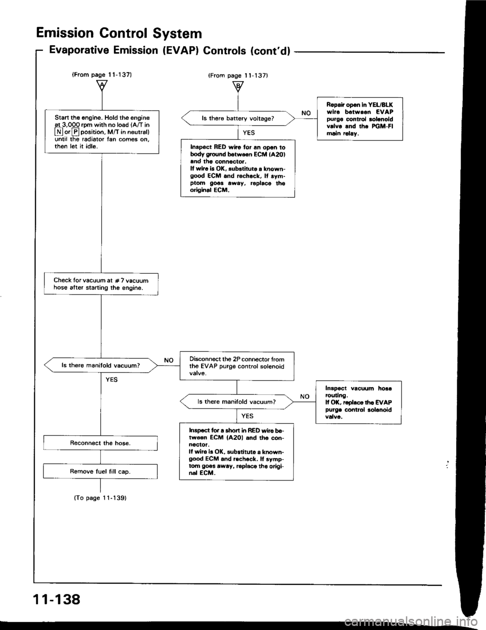
(From page 1 1-137)
lTo page 1 1-'l39)
Start the engine. Hold the engineat 3,OOO rom with no load lA/T in
E orE position, M/T in neutrsl)unlil lhe radiator tan comes on.then let it idle.
Check lor vacuum at # 7 vacuumhose alter starting the engine.
Oisconnect the 2P connoctor fromthe EVAP purge control solenoid
Intpoct vacuum hoaarcuting.It OK, reolrco tr|c EVAP
Purge contlol lolanoid
ls there manifold vacuum?
Inrpoct for a short i|t RED wire bo-lwoen ECM {A2Ol and th6 con-noclor.ll wiro la OK, substituto a known-good ECM 6nd .echock. lf symp-tom goes away, loplace tho origi-nal ECM.
Ropair opon in YEL/BLKwirc b.tw..n EVAPpurgo control rolanoidvrlvo and th. xiM-Flmlin r6lay.
ls there baftery voltage?
Inspoct RED wirc for 6n opon totrody g.ound botween ECM lA20)and th6 conn6ctor.It wir. b OK, substiluto a known-good ECM and rochock, It sym-ptom 9o6s away, roplaco thooriginal ECM,
Emission Gontrol System
Evaporative Emission (EVAP) Gontrols (cont'd)
{From page 11-137}
11-138
Page 329 of 1413

Emission Control System
Evaporative Emission Controls
(cont'dl
Evaporativ€ Emission {EVAPI Two Way Valvo Tasting
l. Remove the tuel fill cao.
2. Remove vapor line trom the two way valve on the
fuel tank and connect to T-fitting trom vacuum
gauge ano vacuum pump as snown.
VACUUM/PRESSURE GAUGEoTJAZ-OOI OOOa
A973X-041-XXXXX
fT-FITTING
Apply vacuum slowly and continuously while watch-
ing the gauge.
Vacuum should stabilize momentarilv at 5-15
mmHg (0.2-0.6 in. Hg).
a It vacuum stabilizes (valve opensl below5mmHg(O.2 in.Hg) or above I 5 mmHg (O.6 in.Hg), install
a new valve and retest.
Move vacuum pump hose from vacuum to pressure
titting, and move vacuum gauge hose trom vacuum
to oressure side as shown.
Pressure should stabilize at 1O-35 mmHg (0.4- 1 .4
in. Hg).
a lf p.essure momentarily stabilizes {valve opensl
at 1O-35 mmHg (O.4- 1.4 in.Hg), the valve is
oK.
a lf pressure stabilizes below 10 mmHg {O.4 in.Hg)
or above 35 mmHg (1 .4 in.Hgl, install a new valve
and retest.
4.
J-.
fF . -,-/ asr^:
,T 4?e
Slowly pressurize the vapor line while watching thegauge.
11-140
Page 1107 of 1413

Electrical
Special Tools
Troubleshooting
Tips and Precautions ................................ 23-3Five-stop Tloubleshooting ..............,...-..-... Z3-sSchematic Symbols ................................_. 23-6wire Color Cod€s ..................................... 23-6Relay and Control Unit Locations
Engine Compartment .........,............ ... --. 23-7Dsshboard and Door ..,,......................... 23-gDashboard and Floor ............................. 23-t OOuaner Panel .....-.....23-12Connector ldentification and WireHarness Routing ........ 23-i 3
Index to Circuits and Systems
Airbag ............... ...-..-... 2g-26sAir Conditioning ....,.. Section 2lAltelnator ......_.............. 23-99Anti-lock Brake Systsm (ABS) Section 19Automatic Transmission Section 14Battery .............. .......... 23-66Chafging System ........... 23-98rCigalstte Lighter .....................-...-......-..-.. Z3-2O4Cfock ................. ..........23-197rcruise Controf .......--..-... 23-242Distributor .................... 23-87Fan Controls ................. 23-1ogFuel and Emissions ... Section 1i*Fuses
Under-dash Fuse/Relay Box ................... 23-48Undor-hood ABS Fuse/Retay Box ............ 23-51Under-hood Fuse/Relay Box,.................. 23-52rGauges
Engine Coolant Temperature {ECT)Gauge ................ ..23-126Fuef cauge ............... 2g-123'Gauge Assembly ....--.23-113Speedometer .....-...,,. 23-114Tachometer .....,.....-.. 23-114Ground Distribution ........ 23-60Heater ,,,........,.... ..... Section 2lrHorn ................. ........... 23-199*fgnition Switch ............. 23-70fgnition Syst6m .......-..-.. 23-A7lgnition Timing .............. 23-89Indicator Lights"A/T Gear Position .............. ................... 23-1 32B1ak6 System ...,..,..-.23-127Engine Oil Pressura .............................. _ 23-1 51Low Fuel ............ ......23-125Malfunction Indicator Lamp {MlL} ...,,. Section I l
tfnteglated Control Unit ...29-144*lnterlock System ...................................... 23-1 3gLights, Exteriol
Back-up Lights ........... 23-179Brake Lights .............. 23-t8ltDaytime Running Lights {Csnada} ........... 23-156Front Palking Lights ............................. 23-1 65Flont Side Marker Lights ....................... 23-165Front Turn Signal Lights ........................ 23-1 65*Hazard Warning Lights .........................- 2g-1A4Headlights ................. 23-t6tLicense Plate Lights .............................. 23-1 69Taillights(Harchback) .......... 23-166
{Sedan) .............. .. 23-167Lights. Inteliol
Cargo Area Light {Hatchback) ...... -.. -.. -... 23-177Ceifing Light ........-..-.23-175
Dash Lights Blightness Controt .............. 23-t70Glove Box Lighr ................................... 23-1 69Spotfighr ............ ....-.23-174Trunk Light (Sedanl ............... .............. - 23.-177*Lighting Sysrem .......-.-... 23-152:Moonroof ,,.,.......,..,,,,,.-.23-211PGM-FI Systom ........ S€crion 11Power Distribution .,.-..--..23-54Power Door Locks .............,,..................... 23-233Power Mirors ..,..,....-...- 23-216Power Relays ...........,..... 23-68Power Windows ............ 29-222*Rear Window Defogger ........,... ..........,..... - 23-20,6Reminder Systems
Key-in Remindel System ....,.............,.... 23-1 50Lights-on Reminder System ................... 23-l 5f*Maintenance Reminder system ..,,.... -.. - -. 23-.1 2gSeat Belt Reminder System ..................- 23-125*Side Markel/Turn Signal/Hazard
Ffasher System .,..,..-.23.-1A4Spark Pfugs .........-...-..... 23-97Starting System ....,,.....-. 23-73*Stereo Sound System ...,.......................,,.. 23-l gg
Supplemental Restraint System {SRS} ......... 23-265Vehicfe Speed Sensor {VSS) .............--..-.... 23-122*Wiper/Washer Systom ...............--.........-..- Zg-254
rRead SRS pi€cautions on Page 23-271 betore workingin these areas.
-+
Page 1122 of 1413

Gonnector ldentification and Wire Harness Routing
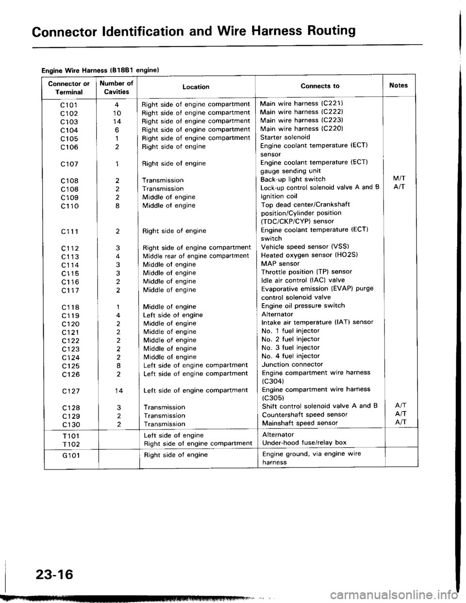
Engine Wire Harness {B1881engine)
Connector 01
Terminal
Number of
CavitiesLocationConnects ioNotes
c10'l
c102
c103
c104
c 105
c106
c107
c108
c108
c109
c110
c111
c113
c114
c115
Lt to
c117
c118
c119
c't 20
c121
c122
c123
cl24
c125
c't26
c127
c128
c129
c130
10
14
6
1
1
2
2
8
2
3
t
1
2
2)
2
8
14
2
2
Right side of engine compartment
Right side of engine compartment
Right side of engine compartment
Right side ol engine compartment
Right side of engine compartment
Right side of engine
Right side ol engine
Transmission
Transmission
Middle of engine
lvliddle of engine
Right side ot engine
Right side of engine compartment
ldiddle rear of engine compartment
Middle of engine
Middle ol engine
Middle of engine
Middle of engine
Middle ot engine
Left side of engine
lvliddle of engine
Middle of engine
Middle of engine
Middle ot engine
Middle ol engine
Left side of engine compartment
Left side of engine compartment
Left side of engine compartment
Transmission
Transmission
Transmission
Main wire harness (C221)
Main wire harness {C222}
Main wire harness (C223)
Main wire harness {C220)
Starter solenoid
Engine coolant temperature {ECT)
sensor
Engine coolant temperature (ECT)
gauge sending unit
Back'up light switch
Lock-up control solenoid valve A and B
lgnition coil
Top dead center/Crankshaft
position/Cylinder position
(TDC/CKP/CYP) sensor
Engine coolant temperature (ECT)
switch
Vehicle speed sensor (VSS)
Heated oxygen sensor (HO2S)
MAP sensor
Throttle position (TP) sensor
ldle air control (lAC) valve
Evaporative emission (EVAPI purge
control solenoid valve
Engine oil pressure switch
Alternator
Intake air temperature {lAT} sensor
No. 'l fuel injector
No. 2 tuel injector
No. 3 fuel injector
No. 4 fuel injector
Junction connector
Engine compartment wire harness
(c304)
Engine compartmenl wire harness
(c305)
Shift control solenoid valve A and B
Countershait speed sensor
Mainshaft speed sensor
M/T
NT
NT
NT
T 101
r102
Lelt side oI engine
Right side of engine compartment
Alternator
Under-hood tuse/relay box
G 101Right side of engineEngine ground, via engine wire
harness
23-16
Page 1124 of 1413

Gonnector ldentification and Wire Harness Routing
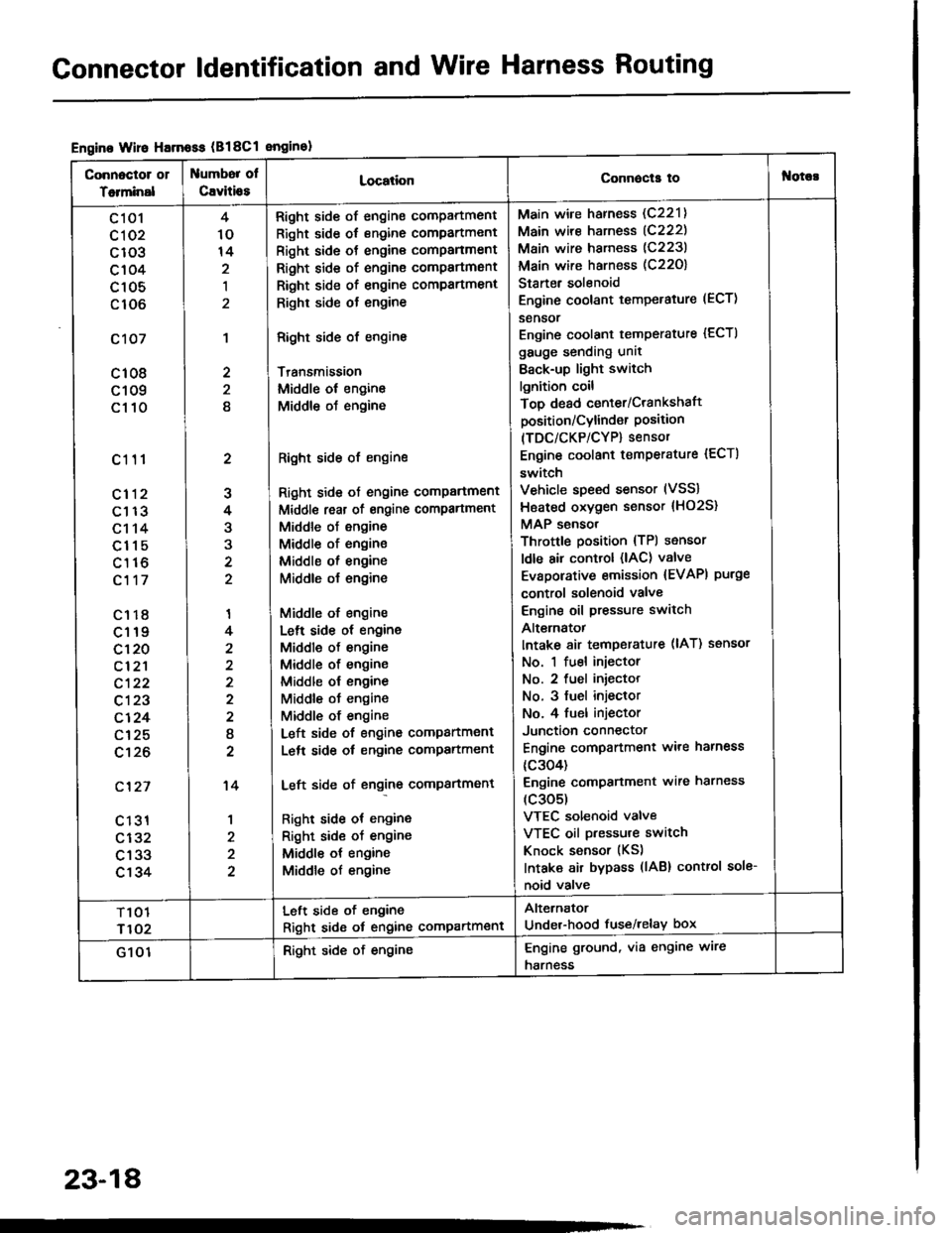
Engine Wire Harnoss (B18Cl enginol
Connoctor 01
Totminal
umbor ol
Cavitio8LocationConnecla tof{orc!
c 101
cl 02
c103
c104
c105
c106
c107
c108
c109
c110
c111
cl12
c113
c114
c115
c116
c117
c1r8
c119
c120
cl2'l
c122
c123
c124
c125
c't26
c'127
c 131
c132
c133
c134
2
J
4
3
'I
4
2
I
2
't4
1
4
10
14
,l
2
2
8
Right side of engine compartment
Right side of engine compartment
Right side ot engine comPanment
Right side of engine compartmsnt
Right side of engine compartment
Righr side ot engine
Right side of engine
Transmission
Middle ol engine
Middle oJ engine
Right side of engine
Right side ot engine comPartment
Middl€ reat of engine compartment
Middle of engine
Middle of engine
Middle ol engine
Middle o{ engine
Middle of engine
Lelt side ot engine
Middle of engine
Middle of engine
Middle ol engine
Middle ot engine
Middle of engine
Left side of engine companment
Lelt side ot engine compartment
Left side of engine compartment
Right side ot engine
Right sid€ of engine
Middle ot engine
Middle of engine
Main wire harness (C221)
Main wire harness (C222)
Main wire harness (C223)
Main wire harness (C22O)
Starter solenoid
Engine coolant temperature (ECT)
sensor
Engine coolant temperature {ECTI
gauge sending unit
Back-up light switch
lgnition coil
Top dead center/Crankshaft
position/Cylind€r Position(TDC/CKP/CYP) sensor
Engine coolant temperature {ECT)
switch
Vehicle speed sensor (VSS)
Hsated oxygen sensor {HO2S}
MAP sensor
Throttle position {TPl sensor
ldle air control (lAC) valve
Evaporative emission {EVAPI purge
control solenoid valve
Engine oil pressure switch
Alt€rnatot
Intake 8ir temperature (lAT) ssnsor
No. 1 fuel injector
No. 2 fuel iniector
No. 3 fuel injeclor
No. 4 fuel injector
Junction connector
Engine compartment ware harness
{c304)
Engine comPanment wire harness
(c305)
VTEC solenoid valve
VTEC oil pressure switch
Knock sensor (KS)
Intaka air bypass (lAB) control sole-
noid valve
T101
r102
Left side of engine
Right sid6 ot engine compartment
Alternator
Under-hood fuse/relay box
G 101Right side of engineEngine ground, via engine wire
harness
23-18