1994 HONDA INTEGRA Steering wheel
[x] Cancel search: Steering wheelPage 672 of 1413
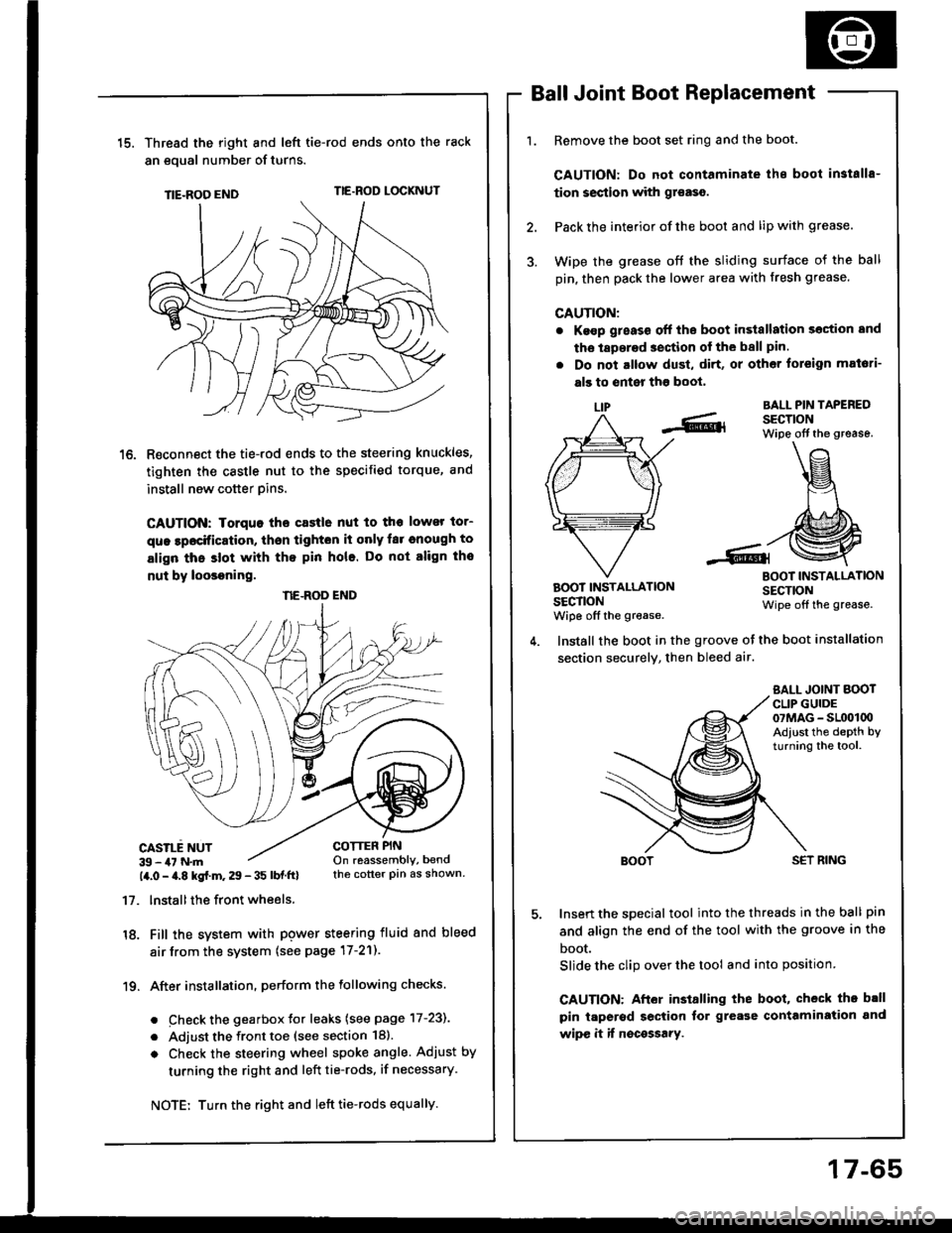
15.Thread the right and lefi tie-rod ends onto the rack
an eoual number of turns.
TIE-ROO ENDTIE.ROD LOCKNUT
R€connect the tie-rod ends to the steering knuckles,
tighten the castle nut to the specified torque, and
install new cotter pins.
CAUTION: Iorquo tho castle nut to tho lower tor-
que lpocification, thsn tighton it only far cnough to
align thc slot with tho pin hole. Do not align tho
nut by loosoning.
CASILE NUT39 - 47 N.m14.0 - a.8 kgf.m. 29 - 35 lbf ftl
17. lnstallthe front wheels.
18. Fill the system with pgwer steering fluid and bleed
air from the system (see page 17-21).
19. After installation. perform the following checks.
. Check the gearbox Jor leaks (see page 17-231
. Adjust the front toe (see section 18).
o Check the steering wheel spoke angle. Adjust by
turning the right and left tie-rods, if necessary.
Ball Joint Boot Replacement
Remove the boot set ring and the boot.
CAUTION: Do not contaminate ihe boot in3talls-
tion section with gr€aso.
Pack the interior of the boot and lip with grease.
Wipe the grease off the sliding surface of the ball
pin, then pack the lower area with fresh grease.
CAUTION:
. Ke€p g;eass off the boot in3tallation section and
tho laperad section of the ball pin.
. Do not altow dust, di.t, or other toreign mat6ti-
als to enter tho boot,
LIPBALL PIN TAPEREDSECTIONWipe off the grease.
BOOT INSTALLATIONSECTIONwiDe off the grease.
BOOT INSTALLATIONSECTIONWipe off the grease.
COTTER PINOn reassembly, bendthe cotter pin as shown.
Install the boot in the groove ot the boot installation
section securely, then bleed air.
SALL JOINT BOOTCLIP GUIDE07MAG - SL(x)l00Adiust the depth byturning the tool.
SET RING
Insert the special tool into the threads in the ball pin
and align the end of the tool with the groove in the
boot.
Slide the clip over the tool and into position
CAUTION: After installing the boot, check th. b.ll
pin taperod section tor grease contamiration and
wipe it if nocossary.
NE.ROD END
Turn the right and left tie-rods equally.
17-65
Page 1037 of 1413
Heater and Air Conditioning
Heater ........ 21-1
Air Conditioning .......... ..22-1
SUPPLEMENTAL RESTRAINT SYSTEM {SRS}
The Integra SRS includes a driver's airbag, located in the steering wheel hub. In addition. all models except the
RS model for Canada have a front passenge.'s airbag located in the dashboard above the glovs box. Information
necessary to safely service the SRS is included in this Service Manual. ltems msrk€d with an asterisk (') on the
conlents page include, or are located near, SRS components. Servicing, disassembling or,eplacing thes€ items
will require special precautions and tools, and should therefore be done by an authorized Acura dealer.
a To avoid r6nd6dng tho SRS inoporativo. which could lead to personal injury or dealh in tho svont ot a sevele
frontal collision, all SRS servica work musl b€ portormed by an authorized Acura dealer.
a lmpropor sorvico procaduro3, including incorrect romoval and installatlon of tho SRS, could load to porsonal iniu-
ry causod by uninlonlional activation of tho ailbag8.
a All SRS eloctdcal widng harnossos are covored with yollow in3ulation. Relatsd compononts a.o locatod in tha
stsering column, flont console, daehboard, and dashboafd low6r pan6l, and in lhe dsshboa.d above lh€ glove
box. Do not uao electdcal tost equipmont on theae circuhs.
NOTE: The original radio has a coded theft protection circuit. Be sure to get the customer's code number beto.e
- disconnecting the battery.- removing the No. 32 (7.5 A) luse from the under-hood fuse/relay box.- removing the radio.
After service, reconnect power to the radio and turn it on. When the word "CODE" is displayed, enter the cus-
tomer's 5-digit code to restore radio operation.
Page 1126 of 1413
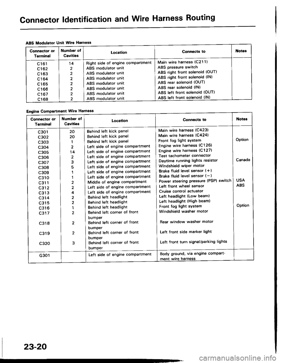
Connector ldentification and Wire Harness Routing
ABS Modulatol Unit Wile Harness
Engine Compartmont Wile Hatnaaa
Connoctor or
Torminal
Numbor ot
CaviiieELocationConnocta tooies
Ltol
c162
c163
c164
c165
c166
c't 67
c168
't4
2
2
Right side of engine comPartment
ABS modulator unit
ABS modulator unit
ABS modulator unit
ABS modulator unit
ABS modulator unit
ABS modulator unit
ABS modulator unat
Main wire harness (c21 1)
ABS Dressure switch
ABS right Jront solenoid (OUT)
ABS right front solenoid (lN)
ABS rear solenoid (OUT)
ABS rear solenoid llN)
ABS le{t front solenoid {OUT)
ABS left tront solenoid (lNl
Connector or
Tolminal
Numbd of
CaviliesLocationConnocta tot{oioE
c301
c302
c303
c304
c305
c306
c307
c308
c309
c310
c31 1
c312
c313
c314
c315
c316
c317
c318
c319
c320
20
20
1
2
14
2
1
1
2
4
2
2
1
2
2
5
Behind left kick Panel
Behind left kick panel
Behind lett kick Panel
Left side of engine compartment
Left side of engine comPartment
Left side of engine comPartment
Left side o{ engine comPartment
Left side of engine comPartment
Left side of engine compartment
Lelt side oJ engine comPartment
Middle of engine comPartment
Left side of engine comPartment
Left side oJ engine comPafiment
Behind leJt headlight
Behind left headlight
Behind left headlight
Behind left corner ot front
bumper
Behind lett corner ot front
DUmper
Behind left corner of ftont
DUmper
Behind left cornet of front
DUmper
Main wire harness (C4231
Main wire harness (C424)
Front fog light sYstem
Engine wire harness (C126)
Engine wire harness (C 127)
Test tachometer connector
Daytime running lights resistor
Windshi€ld wiper motot
Brake fluid level sensor ( + |
Brake fluid level sensor (- )
Power steering pressure (PSPI
Lett front wheel sensor
Cruise control actuator
Left headlight (Low beam)
LeJ-t headlight (High beam)
Front fog light system
Windshield washer motor
switch
Rear window washer motor
Left front side matker light
Left front tu.n signal/parking lights
USA
ABS
Option
Canada
Option
G301Lett side of engine comPartmentBody ground, via engine comPart-
ment wire harness
23-20
Page 1178 of 1413
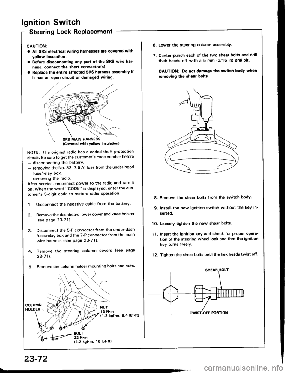
lgnition Switch
Steering Lock Replacement
CAUTION:
a All SRS electrical wiring harnesses ale covsred with
yellow insulation.
a Belore disconnecting any parl ot the SRS wir€ hal-
ness, connecl the short connector{s).
a Replace the entire alfected SRS harness a$6mbly il
it has an open circuit or damaged wiring.
NOTE: The original radio has a coded thett protection
circuit. Be sure to get the customer's code number betore
- disconnecting the batterY.
- removing the No. 32 (7.5 A) fuse from the under-hood
fuse/relay box.- removing the radio.
After service, reconnect power to the radio and turn it
on. When the word "CODE" is displayed, enter the cus-
tomer's 5-digit code to restore radio operation.
1. Disconnect the negative cable from the battery.
2. Remove the dashboald lower cover and knee bolster
(see page 23-7'l ).
3. Disconnect the 5-P connector from the under-dash
fuse/relay box and the 7-P connector trom the main
wire harness {see page 23-71).
4. Remove the steering column covers (see page
23-711.
5. Remove the column holder mounting bolts and nuts'
BOLT22 N.m
12.2 kgl'm.
NUT13 N.m(1.3 kgf.m, 9.4 lbl'ftl
23-72
16 tbt.ftl
6. Lower the steering column sssembly.
7. Center-Dunch each oJ the two shear bolts and drill
their heads off with a 5 mm {3/1 6 in) drill bit'
CAUTION: Do not dama96 tho switch body whon
r€movlng the shoar bol$.
Remove the shear bolts from the switch body.
Install the new ignition switch without the key in-
serted.
Loosely tighten the new shear bolts.
Insert the ignition key and check for proper opera-
tion of the steering wheel lock and that th€ ignition
key turns freely.
Tighten the shear bolts untilthe hex heads twist off.
8.
q
10.
11.
12.
Page 1224 of 1413
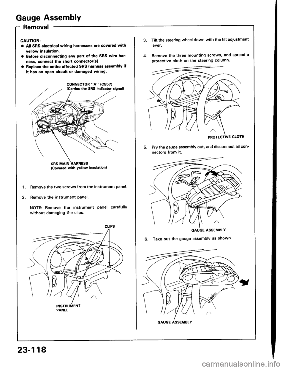
Gauge Assembly
Removal
CAUTION:
a All SRS electrical wiling harnesses ara cover6d with
yollow insulation.
a Eofore disconnecting any part ol the SRS wiro har-
n6ss, connoct lhe short connector(sl.
a Roplace tho entirs affocted SRS harneas assembly if
it has an open circuit 01 damaged wi.ing.
SBS MAIN HARI{ESS(Covor6d with Yollow in.ulationl
Remove the two screws lrom the instrument panel.
Remove the instrument panel.
NOTE: Remove the instrument panel careJully
without damaging the cliPs.
1.
2.
lcarrio. tho SRs indicolor 8ignal)
CLIPS
23-118
Tilt the steering wheel down with the tilt adjustment
tevet.
Remove the three mounting screws, and spread a
protective cloth on the steering column.
PROTECTIVE CLOTH
Pry the gauge assembly out, and disconnect allcon-
nectors from it.
GAUGE ASSEMBLY
Take out the gauge assembly as shown.o.
Page 1308 of 1413
Horn
SwitchTest(cont'd)
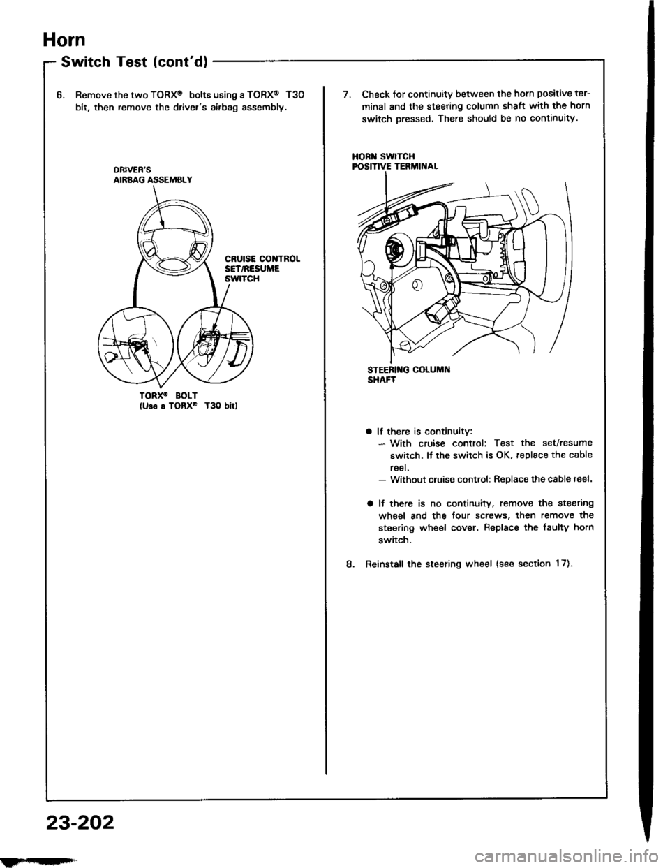
6.Remove the two TORX@ bolt6 using a TORX@ T30
bit, then remove the driver's airbag assembly.
Check for continuity between the horn positive ter-
minal and the steering column shaft with the horn
switch pressed, There should be no continuity.
HORN SwlTCHPOSITIVE TERMIITAL
TORXO BOLT(U!6 s TORxo T3O bitl
8.
a lf there is continuitv:- With cruise control: Test the set/resume
switch. lJ the switch is OK, replace the cable
reel.- Without cluise control: Replace the cable reel.
a lJ there is no continuity. remove the steering
wheel and the four screws, then remove the
steering wheel cover. Replace the faulty horn
switch.
Reinstall the steering wheel {see section 17).
DB|vEN'SAIRBAG ASSEMBLY
23-202
ilFrrI|qFrl"
Page 1376 of 1413
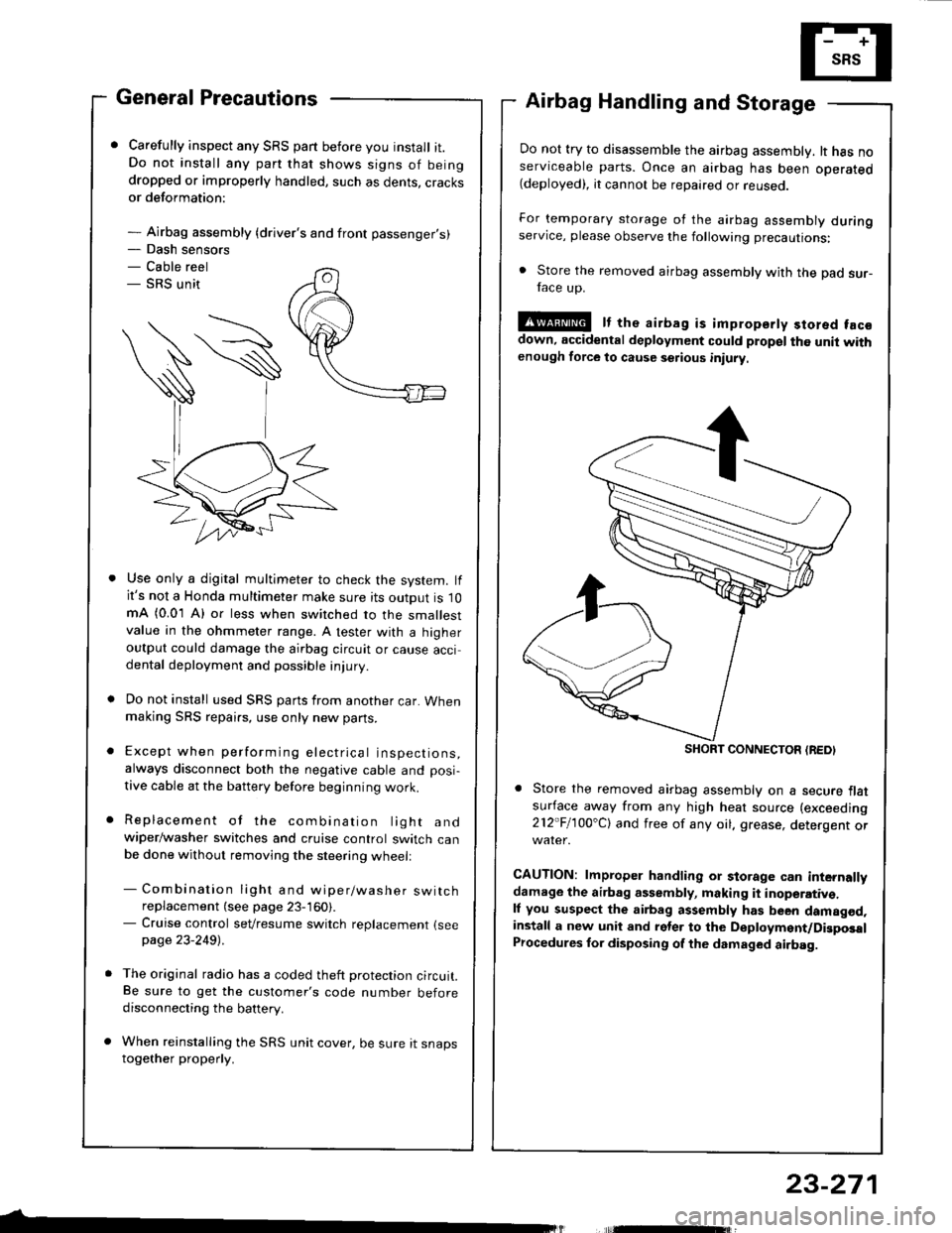
- Dash sensors- Cable reel- SRS unit
General Precautions
Carefully inspect any SRS part before you install it.Do not install any part that shows signs of beingdropped or improperly handled, such as dents, cracksor deformation:
- Airbag assembly {driver's and front passenger's)
Airbag Handling and Storage
Do not try to disassemble the airbag assembly. lt has noserviceable parts. Once an airbag has been operated(deployed), it cannot be repaired or reuseo.
For temporary storage of the airbag assembly duringservice, please observe the following precautions:
. Store the removed airbag assembly with the pad sur-face up.
!@ It the airbag is impropsrty stored facsdown, accidental deployment could propel the unit withenough force to cause setious iniury
Store the removed airbag assembly on a secure flatsufface away from any high heat source (exceeding
212"Fl1OO'Cl and free of any oil. grease, detergent or
CAUTION: lmproper handling or storage can internallydamage the airbag assembly, making it inoperativ€.ll you suspect the airbag assembly has been damagod,install a new unit and rgler to the Deployment/DigposalProcedures lor disposing of the dsmaged airbag.
Use only a digital multimeter to check the system. lfit's not a Honda multimeter make sure its output is 10mA (0.01 A) or less when switched to the smallestvalue in the ohmmeter range. A tester with a higheroutput could damage the airbag circuit or cause accidental deployment and possible injury.
Do not install used SRS parts from another car. Whenmaking SRS repai.s, use only new pans.
Except when performing electrical inspections,always disconnect both the negative cable and posi-
tive cable at the battery before beginning work.
Replacement of the combination light andwiper/washer switches and cruise control switch canbe done without removing the steering wheell
- Combination light and wiper/washer switchreplacement (see page 23-160).- Cruise control sevresume switch replacement {seepage 23-2491 .
The original radio has a coded theft protection circuit.Be sure to get the customer's code number beforedisconnecting the battery.
When reinstalling the SRS unit cover, be sure it snapstogether properly.
SHORT CONNECTON {REDI
23-271
Page 1377 of 1413
Supplemental Restraint System (SRSI
Wiring Precautions
o Never attempt to modify. splice or repair SRS wiring.
NOTE: All SRS electrical wiring harnesses are covered
with yellow insulation.
Be sure to install the harness wires so that they are
not pinched or interfering with other car pans.
Make sure all SRS ground locations are clean and
grounds are securely fastened for optimum metal-to-
metal contact. Poor grounding can cause intermittent
problems that are difficult to diagnose.
23-272
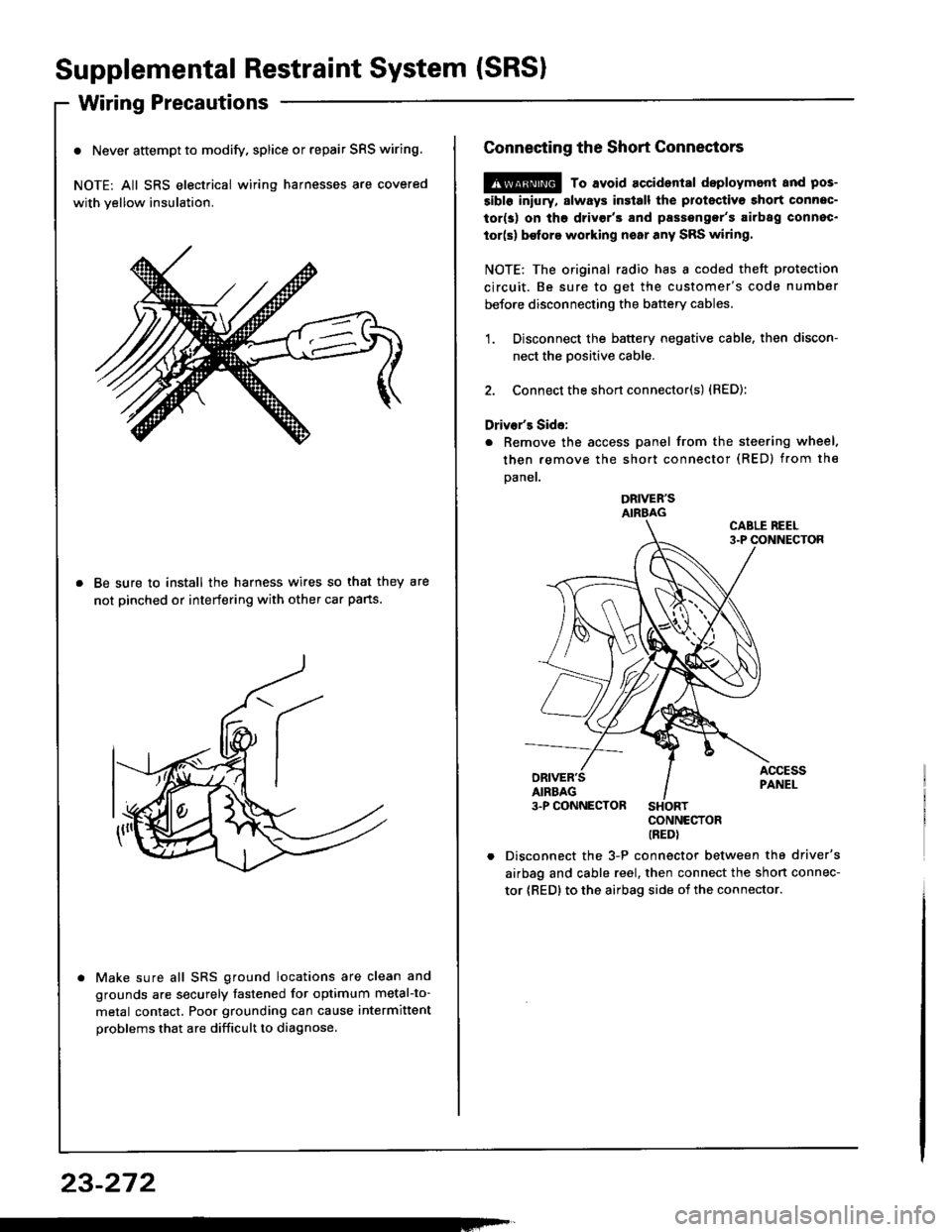
Connecting the Short Connectors
@ To avoid accident8l deploymont and pos-
5ibl6 iniury, slways insiall the protectiva short connec-
tor(s) on tho drivgr'3 and passengor's airbag connec.
tor(s) be{ore working noar any SRS wiring.
NOTE: The original radio has I coded theft protection
circuit. Be sure to get the customer's code number
before disconnecting the battery cables.
1. Disconnect the battery negative cable. then discon-
nect the Dositive cable.
2. Connect the short connector(s) {RED):
Driver's Side:
. Remove the access panel from the steering wheel.
then remove the short connector (RED) from the
Daner.
DRIVER'SAIRBAG
CONNECTORIREDI
Disconnect the 3-P connector between the driver's
airbag and cable reel, then connect the short connec-
tor {RED} to the airbag side oi the connector.