1994 HONDA INTEGRA main relay
[x] Cancel search: main relayPage 312 of 1413

Intake Air Bypass (lABl Control System tBl8C1 enginel
Osscription
Two air intake paths are provided in the intake manifold to allow the selection of the intak€ path most favc
given engine speed.
Satisfactory power peformanc€ is achieved by closing and opening the intake air bypass (lAB) control valve!
que at low RPM is acheived when the valves are closed, whereas high power at high RPM is achieved by when
8re oDeneo.
IAB CONTROLVALVES
To PGM-FIMAIN RELi
IABCHECK VALVE
t favorabl€ for a
vslves. High tor-
when the valves
RELAY
(cont'dl
11-123
Page 314 of 1413

(From page 1 1-124)
Raise engine speed to above6,000 rpm.
Disconnect the 2P connector tromthe IAB control solenoid valve.
Turn the ignition switch OFF.
Check for continuity to ground onthe PNK/BLU wire.
Ropair short to g.ound
at PNK/BLU wiro bo-two6n ECM {A17) andtho 2P connector.
ls there continuity to ground?
Substituto a known-good ECMand racheck. It symptom goos
swsy, roplace tho original ECM.
{From pago 1 1-124}
Repsir op6n in YEL/BLKwiro botwoon tho 2Pconnector and FGM-FImain relaY.
ls there battery voltage?
Turn the ignition swirch OFF.
Connect lhe test harness betweenthe ECM and connectors lseepage 11-37).
Turn the ignition switch ON andconnect a lumper wke betweenECM (A17) terminal and ECM
{A26) terminal.
Ropaiiopon inP K/BLUwiao botwoen ECM
lAl7l and tho 2P con-nectot.
Ooes the solenoid valve clickwhen the jumper is con-nected?
Sub3titute a known-good ECMand rechock. lf symptom/indica-tion goos away, r6place tho origi-nal ECM.
Check lor vacuum at #'l3 vacu-um hose.
IAB control syst6m is OK.
11-125
Page 443 of 1413

Number of @indicator light
blinks while
Service Check
Connector is
connected with
the special tool.
@ indicator
lightPossible CauseSymptomRefer to
page
'loBlinksDisconnected engine coolant tempera-
rure (ECT) sensor connector
Short or open in ECT sensor wire
Faulty ECT sensor
Lock-up clutch does not
engage.14-68
1lOFFDisconnected ignition coil connector
Short or open in ignition coil wire
Faulty ignition coil
. Lock-up clutch does not
engage.'t 4-7 0
13Blinks. Shon or open in LT GRN wire between
the D3 terminal and ECM. Faulty barometric pressure {BARO)
sensor
NOTE: The BARO sensor is built into
the ECM
. No specific symptom
appears.
14-7 1
14Blinks. Short of open in FAS {YEL} wire be-
tween the D16 terminal and ECM. Faulty ECM
. Transmission jerks hard
when shitting.
't5OFFDisconnected mainshaft speed sensor
connecror
Short or open in mainshaft speed sen-
sor wire
Faulty mainshaft speed sensor
. Transmission jerks hard
when shifting.
14-75
SymptomProbable CauseRet.page
LQ! indicator light is on steady, not blinking whenever the ignition is on.14-77
[Q3] indicator light does not come on for 2 seconds after ignition is first
turned on.14-78
Lock-up clutch does not have duty operation (ON-OFFI.Check A/C signal with
A/C on.14-80Lock-up clutch does not engage.
Shitt leve. cannot be moved lrom @ position with the brake pedal
depressed.Check brake switch signal,14-41
It the self-diagnosis LQ4 indicator light does not blink, perform an inspection according to the table below.
a lf a customer describes the symptoms for codes 3, (yet the LQ! indicator light is not blinkingl, 6, 1 1 or 15, it will
be necessa.y to recreate the symptom by test driving. and then checking the @ indicator light with the ignition still
oN.
e lt ttre @ indicator light displays codes olher than those listed above or stays lit continuously, the TCM is faulty.. Sometimes the Lqd indicator light and the Malfunction Indicator Lamp (MlL)/Check Engine light may come on simul-taneously. lf so, check the PGM-Fl system according to the numbe. of blinks on the MIL/Check Engine light. thenreset the memory by removing the BACK UP fuse in the unde.-hood fuse/relay box for more than 1O seconds. Drive
the vehicle for several minutes at speed over 30 mph (5O km/h), then recheck the MIL/Check Engine light.
NOTE:
. PGM-FI system
The PGM-Fl system on this model is a sequential multiport fuel injection system.a Disconnecting the BACK UP luse also cancels the radio anti-theft code. preset stations and the clock setting. Get
the fuse so vou can reset them.the customer's code number and make note ot the radio
14-51
Page 1005 of 1413

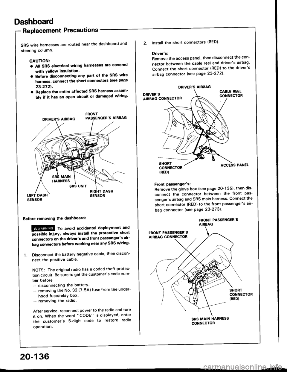
Dashboard
Replacement Precautions
SRS wife harnesses are routed near the dashboard and
steering column.
CAUTION:
a Alt SRS olectrical wiling harness€s ale covorad
with Yollow insulation.
a Botore disconnecting any part ot the SRS wiro
harness, connect ths short connscto6 (see page
23-2721.
a Roplac6 ih€ entiro aflectod SRS halnoss assem-
bly il it has an opon cilcuit or damagod wiling'
LEFT DASHSENSOR
Bstora lomoving the dashboaid:
!@@ To avord accioenlal dsployment and
""iUU inir.v, always install the plotoctive short
;onnectors on the driver's and tlont pass€ngel's air-
bag connectors bolors working near any SRS wiring'
1. Disconnect the battery negative cable, then discon-
necl the positive cable.
NOTE: The original radio has a coded theft protec
tion circuit. Be sure to get the customer's code num-
ber before- disconnecting the battery.
- removing the No 32 (7.5A) Iuse from the under-
hood fuse/relaY box'- removing the radio.
After service, reconnect power to the radio and turn
it on. When the word "CODE" is displayed, enter
the customer's 5 digit code to restore radlo
ooeration.
DRIVER'S AIREAG
SRS UNIT
20-136
DRIVER'S AIRBAG
2.lnstall the short connectors (RED)
Ddvar's:
Remove the access panel, then disconnect the con-
nector between the cable reel and driver's airbag'
Connect the short connector (RED) to the driver's
airbag connector lsee page 23-27 2l'
DRIVER'SAIRBAG CONNECTOB
CABLE REELCONNECTOR
SHORTCONNECTOR(RED)
Front passongor's:
Remove the glove box {see page 20-135}, then dis-
connect the connector between the tront pas'
senger's airbag and SRS main harness Connect the
short connector (RED) to the front passenger's air-
bag connector (see Page 23-273).
FROf{T PASSENGER'SAIRBAG
ACCESS PAI{EL
FRONT PASSET{GER'SAIRBAG CONNECTON
SHORTCONNECTOR(REDI
SBS MAIN HARNESS
CONNECTOR
Page 1071 of 1413

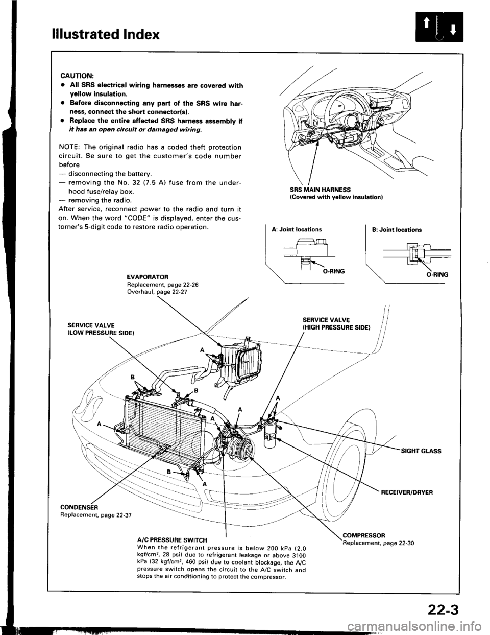
lllustrated Index
CAUTION:
. All SRS electrical wiring harnossos are cover€d withyellow insulation.
. B€fors disconnacting any part of the SRS wire har-ness, connsct the 3hort connsctor(s).. Replace the entirs affscted SRS harness assembly itit has an open circuit or damaged wiring.
NOTE; The original radio has a coded theft protection
circuit. Be sure to get the customer's code number
before- disconnecting the battery.- removing the No.32 (7.5 A) fuse from the under-
hood fuse/relay box.- removing the radio.
After service, reconnect Dower to the radio and turn it
on. When the word "CODE" is displayed, enter the cus-
tomer's 5-digit code to restore radio operation.
SRS MAIN HARNESSlcover€d with yellow insulationl
EVAPORATORReplacement, page 22-26Ovethaul. Oase 22.27
SERVICE VALVE(LOW PRESSURE SIDEI
SERVICE VALVEIHIGH PRESSURE SIDE)
RECEIVER/DRYER
CONDENSERReplacement, page 22,37
A/C PRESSURE SWITCHCOMPRESSORReplacement, page 22-30When the refrigerant pressure is below 200 kpa (2.0kqflcm,,28 psi) due to refrigerant leakage or above 3]OOkPa (32 kgf/cm,, 460 psi) due to coolant btockage, the A,/Cpressure switch opens the circuit to the A"/C switch andstops the air conditionang to protect the compressor.
22-3
Page 1072 of 1413

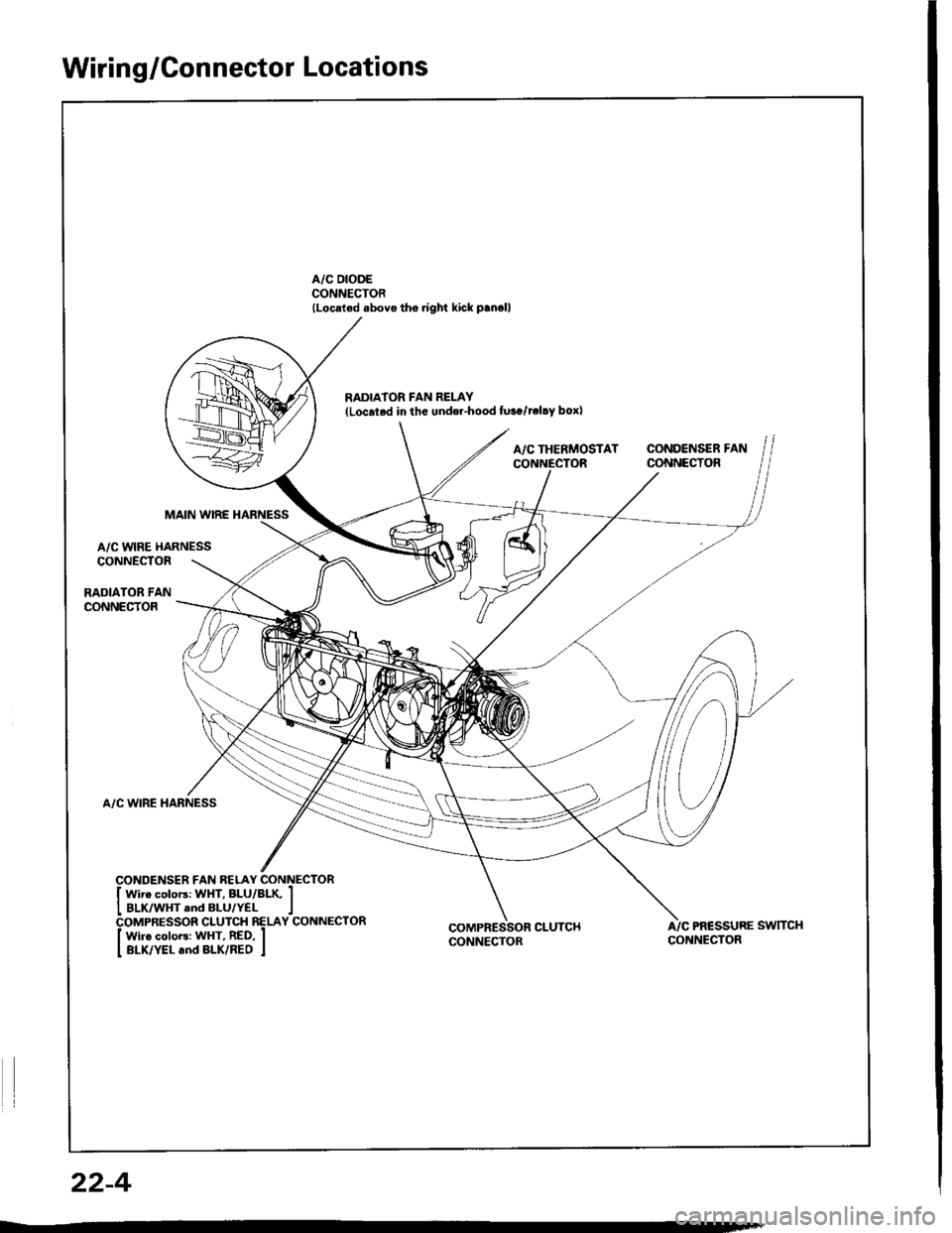
Wiring/Connector Locations
A/C DIODECONNECTOR(Loc.ted .bovo tho.ight kick p.n.ll
RADIA'OR FAN RELAY{Localed in the undel-hood fu3o/reltY box)
A/CTHERMOSTAT CONDENSERFANCONNECTOR CONNECTOR
MAIN WIRE HARNESS
A/C WIRE HARNESSCONNECTOR
RADIATOR FANCONNECTOR
A/C WIRE HARNESS
COMPRESSOR CLUTCHCONNECTORA/C PR€SSURE SWTTCHCONNECTOR
22-4
Page 1083 of 1413

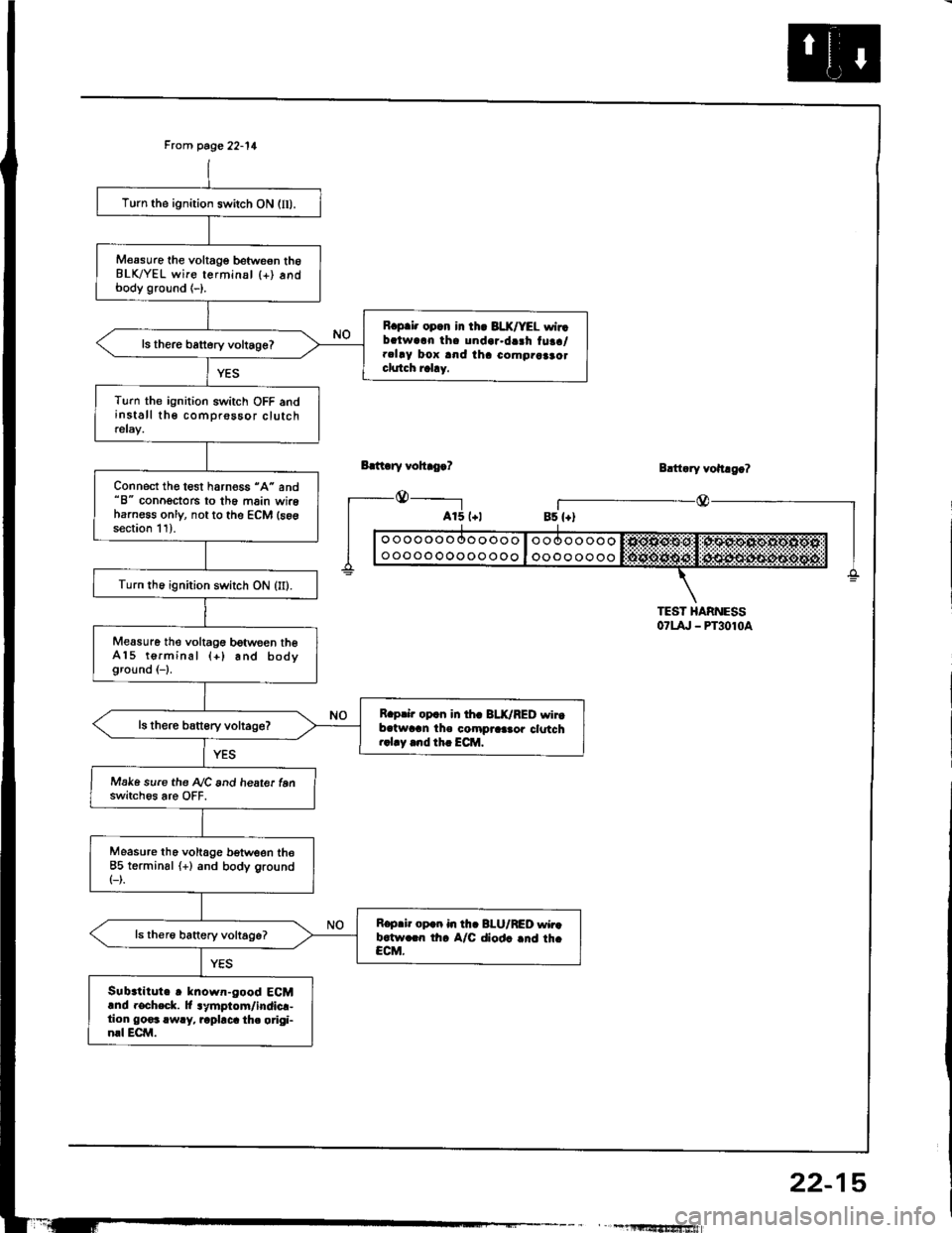
Frcm page 22-11
Bdt ry vohro.?
_@_____-l
Turn the ignition switch ON (lI).
M€asure the voltage betweon th6BLK/YEL wire terminsl {+) andbody ground (-).
R.p.i. opcn in th. 3LX/YEL wirrbalwarn tha undar.da3h tuaa/.clay box and iha como.aaao.clutch rahy.
ls there battery voltage?
Turn the ignition switch OFF andinstall the comprossor clutchrelay.
Connect the test harness "A" and"8" conoectors to th6 main wireharness only, not to the ECM (s6gsection 11).
Turn th6 ignition switch ON (II).
Measure the voltagG between theA15 terminal (+) and bodyground (-1.
R.prir op.n in th. BLK/RED wirtb.twran the compraa.or clotch..1.y .nd th. ECM.
Make sure the A/C and heate. tenswitch6s are OFF.
Measure tho voltage b€tween the85 terminsl (+) and body ground(-).
R.p.ir op.n in th. BI-U/RED wir.b.tw.rn th. A/C diod. .nd th.CCM.
Sub.titute r known-good ECMand rocheck. lt lymptom/indicr-tion go€3 rwry, rapbca th. origi-nrl ECM.
Blttary vohago?
r_--@_Bs {+)
TEST HARNESS07t4, - PT3010a
" , -1llltf,'tfrSfiiwiafi
22-15
Page 1107 of 1413

Electrical
Special Tools
Troubleshooting
Tips and Precautions ................................ 23-3Five-stop Tloubleshooting ..............,...-..-... Z3-sSchematic Symbols ................................_. 23-6wire Color Cod€s ..................................... 23-6Relay and Control Unit Locations
Engine Compartment .........,............ ... --. 23-7Dsshboard and Door ..,,......................... 23-gDashboard and Floor ............................. 23-t OOuaner Panel .....-.....23-12Connector ldentification and WireHarness Routing ........ 23-i 3
Index to Circuits and Systems
Airbag ............... ...-..-... 2g-26sAir Conditioning ....,.. Section 2lAltelnator ......_.............. 23-99Anti-lock Brake Systsm (ABS) Section 19Automatic Transmission Section 14Battery .............. .......... 23-66Chafging System ........... 23-98rCigalstte Lighter .....................-...-......-..-.. Z3-2O4Cfock ................. ..........23-197rcruise Controf .......--..-... 23-242Distributor .................... 23-87Fan Controls ................. 23-1ogFuel and Emissions ... Section 1i*Fuses
Under-dash Fuse/Relay Box ................... 23-48Undor-hood ABS Fuse/Retay Box ............ 23-51Under-hood Fuse/Relay Box,.................. 23-52rGauges
Engine Coolant Temperature {ECT)Gauge ................ ..23-126Fuef cauge ............... 2g-123'Gauge Assembly ....--.23-113Speedometer .....-...,,. 23-114Tachometer .....,.....-.. 23-114Ground Distribution ........ 23-60Heater ,,,........,.... ..... Section 2lrHorn ................. ........... 23-199*fgnition Switch ............. 23-70fgnition Syst6m .......-..-.. 23-A7lgnition Timing .............. 23-89Indicator Lights"A/T Gear Position .............. ................... 23-1 32B1ak6 System ...,..,..-.23-127Engine Oil Pressura .............................. _ 23-1 51Low Fuel ............ ......23-125Malfunction Indicator Lamp {MlL} ...,,. Section I l
tfnteglated Control Unit ...29-144*lnterlock System ...................................... 23-1 3gLights, Exteriol
Back-up Lights ........... 23-179Brake Lights .............. 23-t8ltDaytime Running Lights {Csnada} ........... 23-156Front Palking Lights ............................. 23-1 65Flont Side Marker Lights ....................... 23-165Front Turn Signal Lights ........................ 23-1 65*Hazard Warning Lights .........................- 2g-1A4Headlights ................. 23-t6tLicense Plate Lights .............................. 23-1 69Taillights(Harchback) .......... 23-166
{Sedan) .............. .. 23-167Lights. Inteliol
Cargo Area Light {Hatchback) ...... -.. -.. -... 23-177Ceifing Light ........-..-.23-175
Dash Lights Blightness Controt .............. 23-t70Glove Box Lighr ................................... 23-1 69Spotfighr ............ ....-.23-174Trunk Light (Sedanl ............... .............. - 23.-177*Lighting Sysrem .......-.-... 23-152:Moonroof ,,.,.......,..,,,,,.-.23-211PGM-FI Systom ........ S€crion 11Power Distribution .,.-..--..23-54Power Door Locks .............,,..................... 23-233Power Mirors ..,..,....-...- 23-216Power Relays ...........,..... 23-68Power Windows ............ 29-222*Rear Window Defogger ........,... ..........,..... - 23-20,6Reminder Systems
Key-in Remindel System ....,.............,.... 23-1 50Lights-on Reminder System ................... 23-l 5f*Maintenance Reminder system ..,,.... -.. - -. 23-.1 2gSeat Belt Reminder System ..................- 23-125*Side Markel/Turn Signal/Hazard
Ffasher System .,..,..-.23.-1A4Spark Pfugs .........-...-..... 23-97Starting System ....,,.....-. 23-73*Stereo Sound System ...,.......................,,.. 23-l gg
Supplemental Restraint System {SRS} ......... 23-265Vehicfe Speed Sensor {VSS) .............--..-.... 23-122*Wiper/Washer Systom ...............--.........-..- Zg-254
rRead SRS pi€cautions on Page 23-271 betore workingin these areas.
-+