1994 HONDA INTEGRA control arm
[x] Cancel search: control armPage 629 of 1413

lnspection and Adjustment
Pump Pressure Check
Check the fluid pressure as follows to determine
whether the trouble is in the pump or gearbox.
NOTE: First check the power steering fluid level and
pump belt tension,
CAUnON: Dilconn€st the high pros3uro ho3s with cale
!o e3 not to spill tho powor stooring fluid on th6 lramo
lnd olhor parG.
1. Disconnect the outlet hose from the oumo outlet fit-
ting, 8nd install the pump joint adapter on the
pump outlet.
2, Connect the hose joint sdapter to the power steer-
ing pressure gauge, then connect the outlet hose to
the adaotor.
3. Instsll the power steering pressure gauge to the
pump joint adaptor as shown.
OUTLET HOSE FlTnNG
HOSE ATTACHING BOLT1l Nm11.1 kg{ m 8lbf.ftl
6 x 1.0 m.n BOLT{P!rt of tooll11 N.m11.1 kgtm,8lbf.ftl
P/S JOINT ADAPTOR IPUMPIo?NAK - SmolrA
PUMP OUTI.TTFITIING
Open the shut-off valve fully.
Open the pressure control valve fully.
17 -22
1.
Start the engine and let it idle.
Turn the stee.ing wheel from lock-to-lock several
times to warm the fluid to operating temperature.
Measure steady-state fluid pressure while idling
with the shut-off valve fully open. lf the pump is in
good condition, the gauge should read less than
1500 kpa (15 kgf/cm,,213 psi).
lf it reads high, check the feed line or valve body
unit (see General Troubleshooting l7-10).
Close the shut-off valve. then close the pressure
control valve gradually until the pressure gauge
needle is stabl6, Read the pressure.
lmmediately open the shut-off valve fully.
CAUTION: Do not keep the shut-ott valvs closod
moro thgn 5 soconds or th9 pump could b6 dam"
agod by over-h6ating,
lf the pump is in good condition, the gauge should
read at least 6.400 - 7,400 kpa (65 - 75 kgIlcm,,924- 1,067 psi). A low reading means pump output is
too low for full assist. Repair or replace the pump.
10.
P/S PRESSURE GAUGE
Page 1045 of 1413
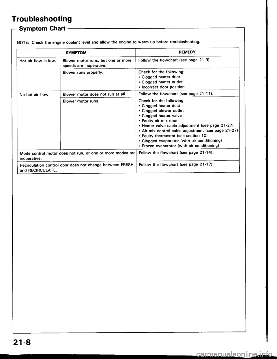
Troubleshooting
Symptom Chart
NOTE: Check the engine coolant level and allow the engine to warm up before troubleshooting.
SYMPTOMREMEDY
Hot air flow is low.Blower motor runs, but one ol more
speeds are inoperative.
Follow the tlowchart (see page 21-9).
Blower runs properly.Check for the following:. Clogged heater duct. Clogged heater outlet. Incorrect door position
No hot air JlowBlowel motor does not run at all.Follow the flowchart (see page 2l-l1l
Blower motor runs.Check for the following:. clogged heatet duct. Clogged blower outlet. Clogged heater valve. Faultv air mix door. Heater valve cable sdjustment lsee page 2'l-271
. Air mix control cable adjustment (see page 21-27)
. Faulty thermostat (see section lO)
. Clogged evaporator (with air conditioning). Frozen evaporator (with air conditioning)
Mode control motor does not run, or one or more modes are
inooerative.
Follow the flowchart (see page 21-14).
Recirculation control door does not change between FRESH
and RECIRCULATE.
Follow the flowchart (see page 21- 17).
21-A
Page 1062 of 1413
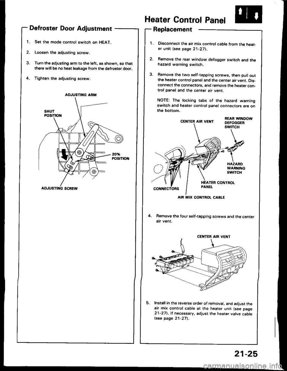
Defroster Door Adjustment
Set the mode control switch on HEAT.
Loosen the adiusting screw.
Turn the adjusting arm to the left, as shown, so that
there will be no heat leakage from the defroster door,
Tighten the sdjusting screw.4.
CE]TTER AIR VEI{T
4. Remove the four self-tapping screws and the centerair v€nt.
Install in the reverse order of removal. and adjust theair mix control cable at the heater unit lsee page21-27). lf necessary, adjust the heater valve cablelsee page 21-27).
REAR WITIDOWDEFOGGERswtTcH
Heater Control Panel
Replacement
Disconned the air mix control cable from the heat-er unit lsee page 21-271.
Remove the rear window defogger switch and thehazard warning switch.
Remove the two self-tapping screws, then pull outthe heater control panel and the center air vent. Dis-connect the connectots, and remove the heater con-trol panel and the center air vent.
NOTE: The locking tabs of the hazard warningswitch and heater control panel connectors are onthe bottom.
AD.'USTII{G ARM
ADJUSTI G SCREW
AIR MIX CONTROL CABLE
CENTEB AIR VE T
21-25
Page 1064 of 1413
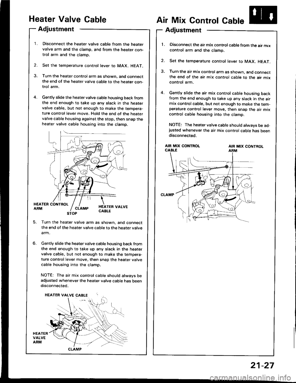
Heater Valve Gable
Adjustment
Disconnect the heater valve cable from the heatervalve arm and the clamp, and from the heater con-trol arm and the clamp.
Set the temperature control lever to MAX. HEAT.
Turn the heater control arm as shown. and connectthe end of the heater valve cable to the heater con-trol arm.
Gently slide the heater valve cable housing back fromthe end enough to take up any slack in the heatervalve cable, but not enough to make the tempera-ture control lever move. Hold the end of the heatervalve cable housing against the stop, then snap theheater valve cable housing into the clamp.
2.
Air Mix Control Cable
Adjustment
'l . Disconnect the air mix control cable from the air maxcontrol arm and the clamp.
2. Set the temperature control lever to MAX, HEAT.
3, Turn the air mix control arm as shown. and connectthe end of the air mix cont.ol cable to the air mixcontrol arm.
4. Gently slide the air mix control cable housing backtrom the end enough to take up any slack in the airmix controlcable, but not enough to make the tem-pe.ature control lever move, then snap the air mixcontrol cable housing into the clamp.
NOTE: The heater valve cable should always be ad-justed whenever the air mix control cable has beendisconnected.
HEATER COIITBOLARMHEATEB VALVECABLE
AIR MIX CONTROLCABLEAIB MIX CONTROLARM
5. Turn the heate. valve arm as shown, and connectthe end of the heater valve cable to the heater valve
arm.
Gently slide the heater valve cable housing back from
the end enough to take up any slack in the heatervalve cable, but not enough to make the tempera-ture control lever move, then snap the heater valve
cable housing into the clamp,
NOTE: The air mix control cable should always beadjusted whenever the heater valve cable has beendisconnected.
CLAMP
21-27
Page 1343 of 1413
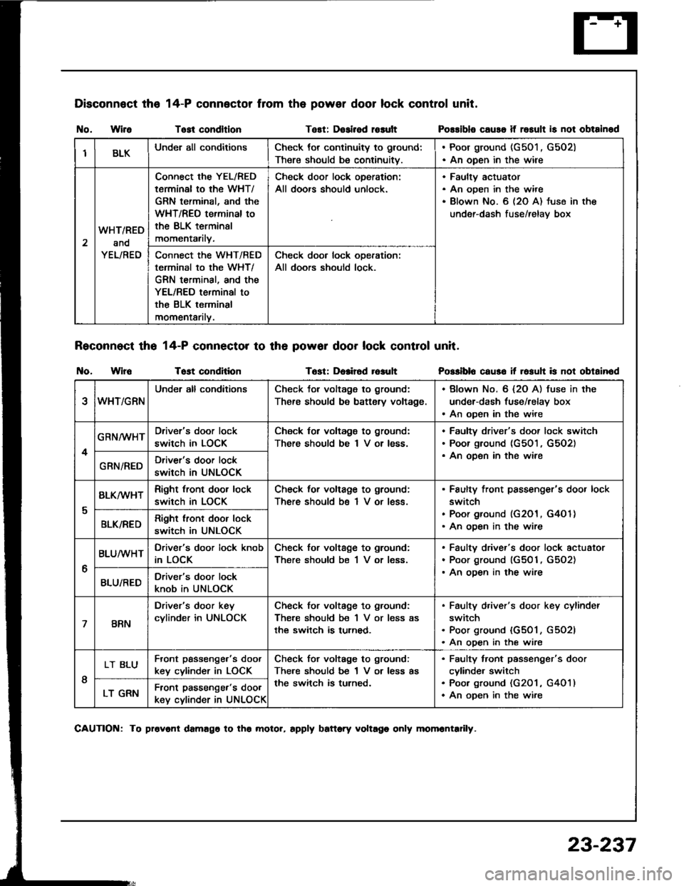
Disconnect the
I{o. WireTost condltlonTest: Dosirsd rosult
Reconnect tho 14-P connector to th6 powor door lock control unit.
t{o. WlroTost conditionTost: Dolir6d r6auh
14-P connector from the power door lock control unit.
Possibls cause if rosult is not obtainod
Posslblo caus6 it rosuh is not obtainod
IBLKUnder all conditionsCheck tor continuity to ground:
There should be continuitv.
. Poor ground (G501 , G502). An open in the wire
2
WHT/RED
and
YEL/RED
Connect the YEL/RED
tarminal to the WHT/
GRN terminal, and the
WHT/REO terminal to
the BLK terminsl
momentarily.
Check door lock oDeration:
All doors should unlock.
Faultv actuator
An open in the wire
Blown No. 6 (2O A) fuse in the
under-dash fuse/relav box
Connect the WHT/RED
terminal to the WHT/
GRN terminal, and the
YEL/RED terminal to
the BLK terminal
momentarilv.
Check door lock ooeration:
All doors should lock.
eWHT/GRN
Under all conditionsCheck tor voltage to ground:
There should be battsry voltage.
. Blown No. 6 {2O A) fuse in the
under-dash fuse/relay box. An open in the wire
4
GRN/WHTDriver's door lock
switch in LOCK
Check for voltagg to ground:
There should be I V or less.
Faultv driver's door lock switch
Poor ground (G501, G5O2)
An oDen in the wireGRN/REDDriver's door lock
switch in UNLOCK
I
BLK/wHTRight tront door lock
switch in LOCK
Check for voltage to ground;
There should bs 1 V or less.
Faulty front passenger's door lock
switch
Poor ground (G201, G4O 1)
An ooen in the wireBLK/REDRight lront door lock
switch in UNLOCK
6
BLUMHTDriver's door lock knob
in LOCK
Check for voltage to ground:
There should be 1 V or less.
Faulty driver's door lock actuator
Poor ground (G501, G5O2)
An ooen in the wireBLU/REDDriver's door lock
knob in UNLOCK
7BRN
Driver's door key
cylinder in UNLOCK
Check for voltage to ground:
There should be 1 V or less as
the switch is turned.
Faulty d,iver's door key cylinder
switch
Poor ground {G501, G5O2l
An open in the wire
I
LT BLUFront passenge.'s doot
key cylinder in LOCK
Check for voltage to ground:
There should be 1 V or less as
the switch is turned.
Faulty tront passenger's door
cylinde. switch
Poo. ground (G201 , G401)
An oDen in the wireLT GRNFront passenger's door
key cylinder in UNLOCK
CAUTION: To provonl damago to tho molor, rpply battory voltago only momrntadly.
23-237
Page 1359 of 1413
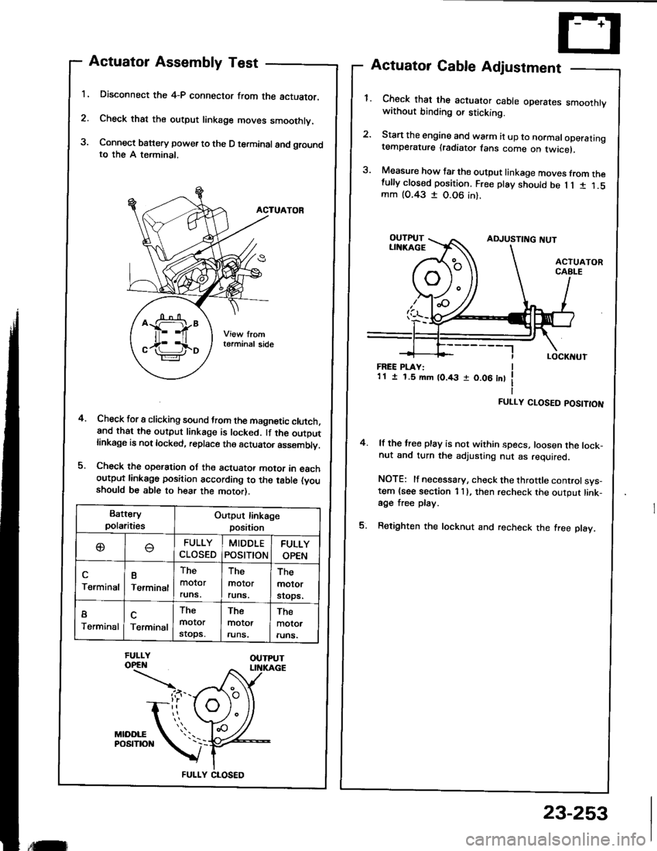
1.
2.
3.
Actuator Assembly Test
Disconnect the 4-P connector from the actuator.
Check that the output linkage moves smoothly.
Connect battery power to the D terminal and groundto the A terminal,
ACTUATOR
Check for I clicking sound trom the magnetic clutch,and that the output linkage is locked. lf the outDutlinkage is not locked, replace the actuator asssmblv.
Check the operation oJ the actuator motor in eachoutput linkago position according to the table (youshould be able to hear the motor).
Actuator Cable Adjustment
Check that the actuator cable operares smoothtvwithout binding or sticking.
Start the engine and warm it up to normaloperatingtemperature (radiator fans come on twicel,
Measure how far the output linkage moves from thefully closed position. Free play should be 1 1 1 1.5mm (O.43 I 0.06 in).
4.
FREE PLAY:1 1 I 1.5 mm (0.43 r 0.06 int
FULLY CLOSED POSITION
4. lf the free play is not within specs, loosen the lock-nut and turn the adjusting nut as required.
NOTE: lf necessary, check the throttle controlsys-tem {see section 1 I }, then recheck the output link-age free play.
5. Retighten the locknut and recheck the free play.
Battery
polaritiesOutput linkage
position
oFULLY
CLOSED
MIDDLE
POStTtON
FULLY
OPEN
Terminal
B
Terminal
The
molor
runs.
The
molor
runs.
The
molor
srops.
I
TerminalTerminal
The
motor
stops.
The
motor
runs.
The
motor
runs.
FULLY CLOSED
,tilr
23-253
Page 1360 of 1413
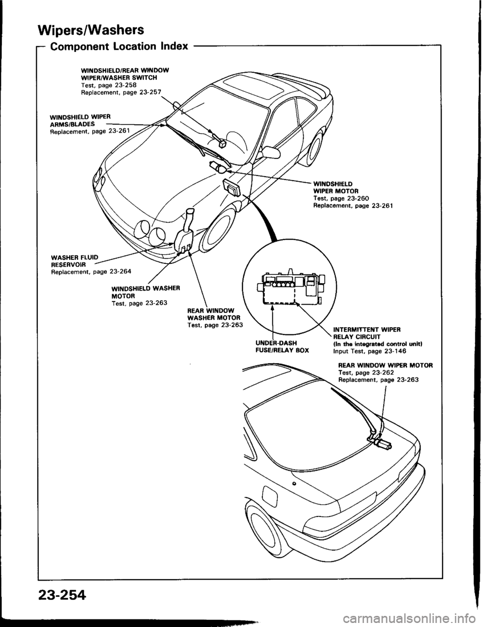
Wipers/Washers
Component Location Index
WII{DSHIELD/REAR WINDOWWIPERAA'ASHEB SWITCHTest, page 23-258Replacement, oase 23 257_..
wtNosHlELD WIPER 2ARMS/BLADES ___-=4,
Repfacemont, Page 23'261 /tt' /
WINOSHIELDIVIPER MOTORTest, page 23-260Repfacement, paee 23-281
FUSE/RELAY BOX
INTERMITTENT WIPERBELAY CIRCUIT(ln the int€gral.d control onitlInput Test, page 23-146
REAR WII{DOW WIPER MOTORTest, page 23-262Replacemont, pago 23-263
23-254