Page 1233 of 1413
Brake System lndicator
Parking Brake Switch Test
Remove the tloor console, and disconnect the con-
nector from the switch.
Check for continuity b€tween the positive terminal
and body ground in each lever position accordino to
the table.
Canada:
lf the parking brake switch is OK, but ths brake sys-
tem indicator does not function, pertorm the input
test for the daytime running lights control unit (see
page 23-156).
L6vor position
TorminalPOSITIVEEODY
UP
DOWN
Brake Fluid Level Switch Test
Remove the reservoir caD.
Check that the tloat moves up and down freely, if
it does not, replace the reservoir cap sssembly.
Chsck for continuitv between the terminals in each
float position according to the table.
RESERVOIR CAPDOWN POSITION
when float drops.
4. lf necessary, replace the reservoir cap assemblv.
Terminal
Float positionPOSITIVENEGATIVE
UP
DOWN-o
POStTtVE
TERMINAL
Switch contacts open atproper fluid level.
23-127
Page 1241 of 1413

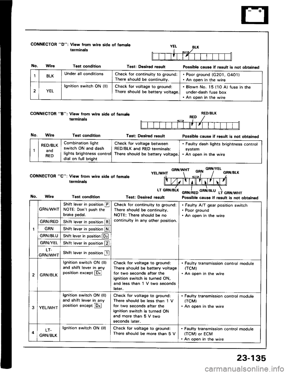
CONNECTOR "D": Visw from wire side ot femals
tetminals
No.WilaTest condition
CONNECTOR "8": View from wire sid6 of fem.l6
i6lminals
No.WileTost condition
CONNECTOR "C": Vi3w lrom wire sido of temale
t6rminals
Test condition
Test: D€sirod rasultPossible cause if result is not obtainod
Tost: D€sir6d resultPossiblo cause if result is not obtained
GRNA HTGRNITELYELAA'HTGRN/BLK
Tost: Desirod r6sult Possible cause it result is not obtainedNo.
BLKUnder all conditionsCheck for continuity to ground:
There should be continuitv.
. Poor ground (G2O1, G4O1). An open in the wire
2YEL
lgnition switch ON { ll}Check for voltage to ground:
There should be battery voltage.
. Blown No. 15 (1O A) tuse in the
under-dash fuse box. An open in the wire
RED/BLK
1
RED/BLK
ano
RED
Combination light
switch ON and dash
lights brighlness control
dial on full bright
Check for voltage between
RED/BLK and RED terminals:
There should be baftery voltage.
. Faulty dash lights b.ightness control
system. An open in the wire
GRN^^/HT
Shift lever in position @NOTE: Don't push the
brake pedal.
Check for continuity to ground:
There should be continuitv.
NOTE: There should be no
continuity in any other position.
Faulty A/T gear position switch
Poor ground
An open in the wire
GRN/REDShift lever in position @
GRNShift lever in position S
GRN/BLUShitr lever in position @
GRN/YELShitt lever in position f2 ]
LT-
GRNMHTShift lever in position E
2GRN/BLK
lgnition switch ON (ll)
and shift lever in anyposition except @
Check for voltage to ground:
There should be battery voltage
for two seconds after the
ignition switch is turned ON,
and less than 1 V two seconds
later.
. Faulty t,ansmission control module(TCM)
. An open in the wire
3YEL/vVHT
lgnition switch ON (ll)
and shitt lever in anyposition except @
Check for voltage to ground:
There should be less than 'l V
tor two seconds after the
ignition switch is turned ON
and more than 5 V two
seconds later.
. Faulty transmission control modute(TCMI
. An open in the wire
4LT.
GRN/BLK
lgnition swirch ON {ll}Check for voltage to ground:
There should be mofe than 5 V
. Faulty transmission control module
ITCM) or ECM. An open in the wire
23-135
Page 1255 of 1413

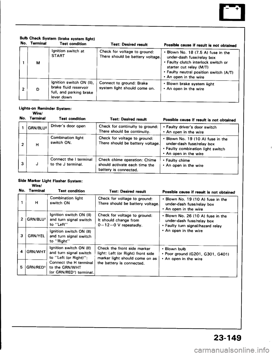
Bulb Check System
No. Tsrminal
(blake system lightl
Test condition
Lights-on Romind6r Systom:
Wire/
No, ToiminalT6Et condition
Side Markol Light Flashar System:
Wiro/
No. TerminalTest condition
Tost: Desirod resuhPossibls caus6 it result is not obtainod
Tost: Dositod rosuhPossibl6 caus6 if rosuh is not obtainod
Tast: Desired rosultPo$ible cause if result is not obtained
IM
lgnition switch at
STARTCheck lor voltage to ground:
There should be battery voltage.
Blown No. 18 {7.5 Al fuse in theunder-dash fuse/relay box
Faulty clutch int€rlock switch or
starter cut relay {M/T}Faulty neutral position switch (A/T)
An open in the wire
D
lgnition switch ON (ll),
brake fluid reservoir
tull, and parking brake
lever down
Connect to ground: Brake
system light should come on.
. Blown brake system light. An oDen in the wire
GRN/8LU'Driver's door openCheck for continuity to ground:
There should be continuity.
. Faulty driver's door switch. An oDen in the wire
H
Combination light
switch ON.
Check for voltage to g.ound:
There should be battery voltage
Blown No. l9 (1O A) tuse in the
under-dash fuse/relav box
Faulty combination light switch
An oDen in the wire
5
Connect the I terminal
to the J terminal.
Check chime operation: Chime
should activate each time the
batterv is connected,
. Faulty chime. An open in the wire
1H
Combination light
switch ON
Check for voltage to ground:
There should be battery voltage
. Blown No. 19 (1O A) tuse in the
under-dash fuse/relay box. An open in the wire
GRN/BLU1
lgnition switch ON {ll)and turn signal switch
to "Left"
Check for voltage to ground:
It should change from
O-12-O V repeatedly.
Blown No. 26 (10 A) luse in theunder-dash fuse/relav box
Faulty turn signal/hazard relay
An oDen in the wire2GRN/YEL
lgnition switch ON {ll)and turn signal switch
to "Right"
4GRN/WHTlgnition switch ON (ll)
and turn signal switch
to "Left (or Rightl":
Connect the H terminal
to the GRNMHT(or GRN/REDl) terminal.
Check the front side marker
light: Left (or Right) front sidemarker light should come on asthe batterv is connected.
Blown bulb
Poor ground (G2O1, c3O1, G4O1lAn open in the wire
GRN/REDl
23-149
Page 1261 of 1413
Gircuit Diagram (Canadal
BATTERY
G"*
UNOER_HOOD FUSEiRETAY 8OX
coMBrNAtor{ rcHrswnc
-il w
| '.=r" I
ll'L I I
I I *o\." l-'li' ;- ;j
I LI
"- r.r-,9 "orr
I
d "
L
RED/BLU REO/}VHT RED,ll
I UNDEN-DASH II FUSEiIEI,AY 8OX I
tl
L-J
t'GRN
/d\BATtG2\9-l
rGNrTrot{swITcH
No.2lfl0A)\I
No.l9|l04]Jm.tr (
t10A) ttt
I
No.l6{7.54}
tl
i,"#
llrrff li'rrt,
RED/GRtIIBLU REOr'TVHTINED/B
V
WHTTYEL
. DASH LGHTS BRIGHTNESSCOI{TROLLER. DASH I-IGHTS. PARKING I-GHIS. TAII,LIGHTS. UCENSE N"AT€ LIGI{TS
I a-rneonru jllA/Vr l"o I f# wxrintoRED/GRI{ +\{H I
DAYTIME RUNNINGUGI{TS RESISTOR
IRED/GRN
Hr I r-01651,1/) | l55W)HIt85W)LOt55Wl
HIGH BEAMINOICATORUGHTfl.4W
I
RIGHTHEADLIGHTPARKIIIGBRAKEsw{TcH
23-155
Page 1263 of 1413

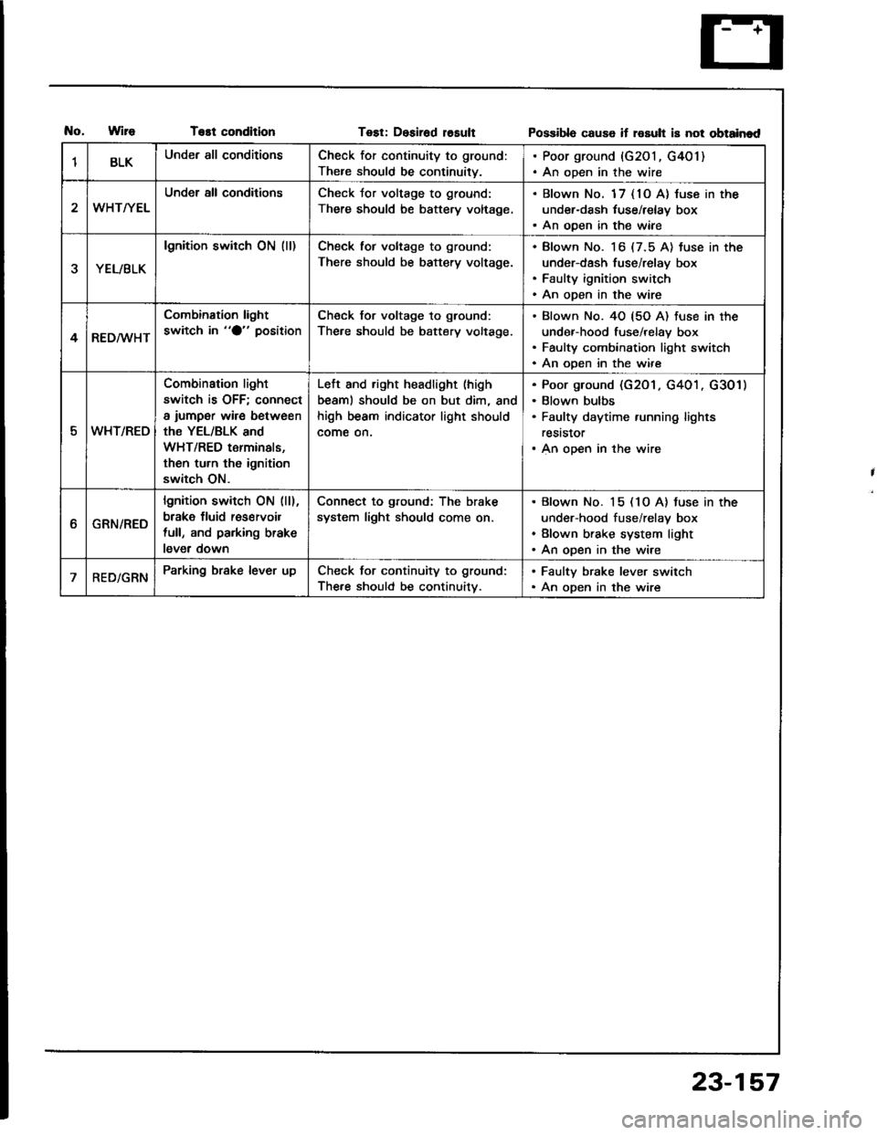
T€st conditionTest: Desirad losultPossibla cause if rosult is not obtainad
1BLKUnder all conditionsCheck for continuity to ground:
There should be continuity.
. Poor ground {G201, G401). An open in the wire
WHT/YEL
Under all conditionsCheck Jor voltage to ground:
There should be battery voltage.
. Blown No. 1 7 { 10 A} luse in the
under-dash tuse/relay box. An ooen in the wiae
YEL/BLK
lgnition switch ON (ll)Check tor voltage to ground:
There should be battery voltage.
Blown No. 16 (7.5 A) tuse in the
under-dash fuse/relay box
Faulty ignition switch
An open in the wire
4RED/WHT
Combination light
switch in "O" positionCheck for voltage to ground:
The.e should be battery voltage.
Blown No. 40 {5O A) fuse in the
under-hood fuse/relay box
Faulty combination light switch
An ooen in the wire
5WHT/REO
Combination light
switch is OFF; connect
a iumper wire between
the YEL/BLK and
WHT/RED terminals,
then turn th6 ignition
switch ON.
Left and right headlight (high
beaml should be on but dim, and
high beam indicator light should
come on.
Poor ground (G201 . G401 . G301)
Blown bulbs
Faulty daytime running lights
reststor
An open in the wire
ttGRN/RED
lgnition switch ON (ll),
brake fluid res€rvoil
full, and parking brake
lever down
Connect to ground: The brake
system light should come on.
Blown No. 15 (1O A) tuse in the
under-hood fuse/relay box
Blown brake system light
An open in the wire
RED/GRNParking brake lever upCheck for continuity to ground:
The.e should be continuitv.
. Faulty brake lever switch. An open in the wire
23-157
Page 1272 of 1413
-
Taillights (Hatchbackl
Replacement
23-166
1.Open the resr hatch.
Remove the rear panellining and the side lining {see
section 20).
Disconnect the 4-P connector from the taillight.
Remove the six mounting nuts, then pull out the
taillight.
4.
NOTE:
a Inspect the gasket. Replace it if it is distorted or
stavs compresseo.
a After installation. run wate. over ths lights to
make sure thev don't leak.
4-P CON[{ECTOR
BulbReplacement
R6ei tum slgnal/Rolr parking lights:
1 . Open the rear hatch, then remove the access panel.
2. Remove the bulb lrom the bulb socket.
@: REAR TURN SIGNAL LIGHT BULB (32 CPI
@: REAR PARKING LIGHT BULB {3 CP)
Brake/T8illight/Back-up lights:
1. ODen the rear hatch.
2. Remove the rear panel lining {see section 20).
BACK-UP LIGHT BULB {32 CP}
ERAKE/TAILLIGHT BULB (32l3 CP)
o:
@:
ACCESS PANEL
Page 1274 of 1413
Taillights (Sedanl
Bulb Replacement
Tsillight:
1. Open the trunk lid. then remove the rear panel lin-
ing and side lining {see section 20}.
2. Remove the bulb from the bulb socket.
lnnor T.illlght:
1. Open the trunk lid, then remove the bulb housing.
2. Remove the bulb from the bulb housing.
@:
@:
@:
BRAKE/TAILLIGHT BULB (32l3 CP}
TURN SIGNAL LIGHT BULB (32 CP}
REAR PARKING LIGHT BULB {3 CP)
O:
@:
BACK-UP LIGHT BULB (32 CP}
BRAKE/TAILLIGHT BULB I3213 CP}
BULB HOUSII{G
23-168
l'r'qn'F',
Page 1287 of 1413
Circuit Diagram
Brake Lights
UNDEE-HOOOFUSE/NELAY BOX
. HORi{. IMTERI.OCK SYSTEM
{.BLK
*H-i
{.{u8tK
23-181