1994 HONDA INTEGRA service indicator
[x] Cancel search: service indicatorPage 442 of 1413
![HONDA INTEGRA 1994 4.G Workshop Manual Symptom-to-Component Chart
Electrical System
Number of @indicator light
blinks while
Service Check
Connector is
connected with
the special tool.
@] indicaror
lightPossible CauseSymptomRefer to
page
Bl HONDA INTEGRA 1994 4.G Workshop Manual Symptom-to-Component Chart
Electrical System
Number of @indicator light
blinks while
Service Check
Connector is
connected with
the special tool.
@] indicaror
lightPossible CauseSymptomRefer to
page
Bl](/manual-img/13/6067/w960_6067-441.png)
Symptom-to-Component Chart
Electrical System
Number of @indicator light
blinks while
Service Check
Connector is
connected with
the special tool.
@] indicaror
lightPossible CauseSymptomRefer to
page
BlinksDisconnected lock-up control solenoidvalve A connector
Short or open in lock-up control sole-noid valve A wire
Faulty lock-up control solenoid valve A
Lock-up clutch does not
engage.
Lock-up clutch does not
disengage.
Unstable idle speed.
14-52
BlinksDisconnected lock-up control solenoidvalve B connector
Short or open in lock-up control sole-noid valve B wire
Faulty lock-up cont.ol solenoid valve B
. Lock-up clutch does not
enga9e.
14-54
Blinks or
OFF
Disconnected throttle position (Tp)
sensor connector
Short or open in TP sensor wireFaully TP sensor
. Lock-up clutch does not
engage.14-56
4BlinksDisconnected vehicle speed sensor(VSS) connector
Short or open in VSS wire
Faulty VSS
. Lock-up clutch does not
engage.'t 4-57
Blinks. Short in A/T gear position switch wire. Faulty A/T gear position switch
. Fails to shift other than
2nde4th gears.. Lock-up clutch does not
engage.
14-58
OFFDisconnected A/T gear position switch
connector
Open in A/T gear position switch wireFaulty A/T gear position switch
Fails to shift other than
2nd-4th gears.
Lock-up clutch does not
en98ge.
Lock-up clutch engages
and disengages alter-
nately.
14-60
7BlinksDisconnected shift control solenoidvalve A connector
Short or open in shitt control solenoidvalve A wire
Faulty shift control solenoid valve A
. Fails to shift (between
1st-4th, 2nd-4th or
2nd-3rd gears only).. Fails to shift (stuck in
4th gear).
14-62
8BlinksDisconnected shitt control solenoid
valve B connector
Shon or open in shift control solenoidvalve B wi.e
Faulty shift control solenoid valve B
. Fails to shiJt (stuck in
lst or 4th gears).'t 4-64
aBlinksDisconnected countershatt speed sen-sor connector
Short or open in the countershaft
speed sensor wire
Faulty countershaft speed sensor
. Lock-up clutch does not
engage_
14-50
Page 443 of 1413

Number of @indicator light
blinks while
Service Check
Connector is
connected with
the special tool.
@ indicator
lightPossible CauseSymptomRefer to
page
'loBlinksDisconnected engine coolant tempera-
rure (ECT) sensor connector
Short or open in ECT sensor wire
Faulty ECT sensor
Lock-up clutch does not
engage.14-68
1lOFFDisconnected ignition coil connector
Short or open in ignition coil wire
Faulty ignition coil
. Lock-up clutch does not
engage.'t 4-7 0
13Blinks. Shon or open in LT GRN wire between
the D3 terminal and ECM. Faulty barometric pressure {BARO)
sensor
NOTE: The BARO sensor is built into
the ECM
. No specific symptom
appears.
14-7 1
14Blinks. Short of open in FAS {YEL} wire be-
tween the D16 terminal and ECM. Faulty ECM
. Transmission jerks hard
when shitting.
't5OFFDisconnected mainshaft speed sensor
connecror
Short or open in mainshaft speed sen-
sor wire
Faulty mainshaft speed sensor
. Transmission jerks hard
when shifting.
14-75
SymptomProbable CauseRet.page
LQ! indicator light is on steady, not blinking whenever the ignition is on.14-77
[Q3] indicator light does not come on for 2 seconds after ignition is first
turned on.14-78
Lock-up clutch does not have duty operation (ON-OFFI.Check A/C signal with
A/C on.14-80Lock-up clutch does not engage.
Shitt leve. cannot be moved lrom @ position with the brake pedal
depressed.Check brake switch signal,14-41
It the self-diagnosis LQ4 indicator light does not blink, perform an inspection according to the table below.
a lf a customer describes the symptoms for codes 3, (yet the LQ! indicator light is not blinkingl, 6, 1 1 or 15, it will
be necessa.y to recreate the symptom by test driving. and then checking the @ indicator light with the ignition still
oN.
e lt ttre @ indicator light displays codes olher than those listed above or stays lit continuously, the TCM is faulty.. Sometimes the Lqd indicator light and the Malfunction Indicator Lamp (MlL)/Check Engine light may come on simul-taneously. lf so, check the PGM-Fl system according to the numbe. of blinks on the MIL/Check Engine light. thenreset the memory by removing the BACK UP fuse in the unde.-hood fuse/relay box for more than 1O seconds. Drive
the vehicle for several minutes at speed over 30 mph (5O km/h), then recheck the MIL/Check Engine light.
NOTE:
. PGM-FI system
The PGM-Fl system on this model is a sequential multiport fuel injection system.a Disconnecting the BACK UP luse also cancels the radio anti-theft code. preset stations and the clock setting. Get
the fuse so vou can reset them.the customer's code number and make note ot the radio
14-51
Page 470 of 1413

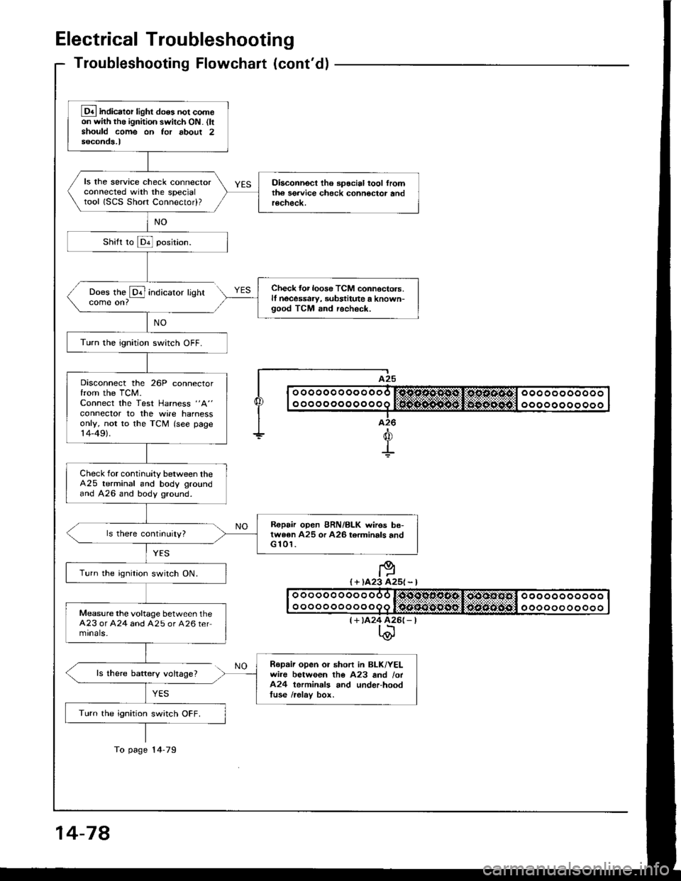
Electrical Troubleshooting
Troubleshooting Flowchaft (cont'dl
Does the @ indicatorcome on?
ls there baftery voltage?
YES
lighr
I A25
| | o ooooo o oo o ooo r:sjc.o.sl'1*st,li*os.s.4tcl ooo oo oooooo I
I I o o o o o o o o o o o o q lifrif.S..n${5git:li$gg-:aiiigitll o o o o o o o o o o o I|--.-T..-I a26
+d
+
I + )A23 A25l - l
(+ tA24 426(- |t\@
Lq4 indicator light do6s not comeon with the ignition switch ON. (ltshould come on Ior about 2seconds.l
ls the service check connectorconnected with the specialtool ISCS Short Connectod?
Diaconnect tho spocial tool fromth6 sgrvice check connoctor andrecheck.
Check {or loos6 TCM connoctors.lf necessaw, substitute a known-good TCM and recheck.
Turn the ignition switch OFF.
Disconnect the 26P connectorfrom the TCM.Connect the Test Harness "A"
conneclor to the wile harnessonly, not to the TCM (see page14-49).
Check for continuity between theA25 terminal and body groundand A26 and body ground.
R€pair open BRN/BLK wires be-twe6n A25 or A26 torminals andG 101.
Turn the ignition switch ON.
Measure the voltage between theA23 or A24 and A25 or A26 termrnals-
Repaii open or short in BLK/YELwire between tho A23 and /ot424 terminals and underhoodtuse /relav box.
Turn the ignition switch OFF.
To page 14-79
14-78
Page 540 of 1413

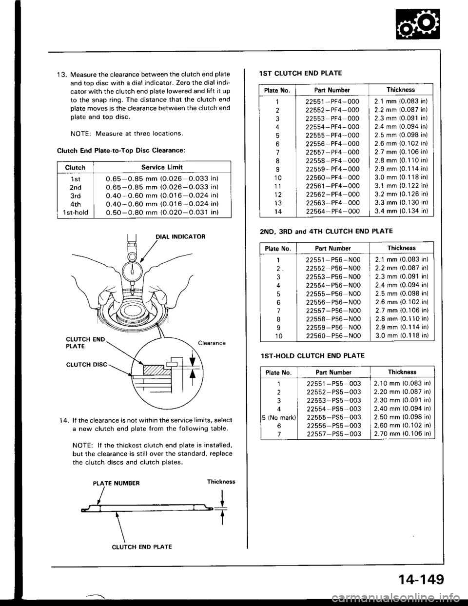
'13. Measure the clearance between the clutch end plate
and top disc with a dial indicator. Zero the dial indi-
cator with the clutch end plate lowered and lift it up
to the snap ring. The distance that the clutch end
plate moves is the clearance between the clutch end
plate and top disc.
NOTEr Measure at three locations.
Clutch End Plate-to-Too Disc Clearance:
1 4. lf the clearance is not within the service limits, select
a new clutch end plate lrom the following table.
NOTE: It the thickest clutch end plate is installed,
but the clearance is still over the standard, replace
the clutch discs and clutch Dlates.
Thickn€ss
ClulchService Limit
lst
2nd
3rd
4th
1st-hold
O.65 o.85 mm (O.026 O.O33 in)
O.65 - O.85 mm {O.026-O.O33 in)
O.4O-O.60 mm (0.O16 o.O24 in)
0.4O-0.60 mm (0.016-0.024 in)
0.50-0.8O mm {O.02O-0.031 in}
IAL INDICATOR
PLATE NUMBER
CLUTCH END PLATE
14-149
lST CLUTCH END PLATE
2ND- 3RD and 4TH CLUTCH END PLATE
lST.HOLD CLUTCH END PLATE
Plate No.Part NumberThickness
1
2
3
4
5
6
7
8
I
10
111)
IJ
14
22551-PF4-000
22552-PF4 000
22553 PF4 000
22554-PF4-OOO
22555 PF4-000
22556 PF4-000
22557 -PF4 000
22558-PF4 000
22559- PF4- 000
22560-PF4 000
22561 PF4-000
22562-PF4 000
22563-PF4 000
22564 PF4-OOO
2.1 mm 10.083 in)
2.2 mm (0.087 in)
2.3 mm (0.091 in)
2.4 mm (0.094 in)
2.5 mm (0.098 in)
2.6 mm {0.102 in}
2.7 mm i0.106 in)
2.8 mm (0.110 in)
2.9 mm (0.1 14 in)
3.0 mm (0.1 18 in)
3.1 mm (0.1 22 inl
3.2 mm {0.126 in}
3.3 mm (0.1 30 in)
3.4 mm (0.134 in)
Plate No.Part NumberThickness
1
2.
3
4
5
6
7
8
I
10
22551 P56,N00
22552-P56-N00
22553-P56-N00
22554- P56 -N00
22555-P56 N00
22556 Ps6- N00
22557 - P56 N00
22558 P56-N00
22559-P56 NOO
22560 P56-N00
2.1 mm (0.083 in)
2.2 mm (0.087 in)
2.3 mm (0.091 in)
2.4 mm (0.094 in)
2.5 mm (0.098 in)
2.6 mm {0.102 in)
2.7 mm {0.106 ini
2.8 mm (0.110 in)
2.9 mm (0.1 14 in)
3.0 mm (0.1 18 in)
Plare No.Part NumberThicknEss
1
2
3
4
5 (No mark)
6
7
22551-PS5 003
22552 PS5-003
22553-PS5 003
22554-PS5-003
22555-PS5-003
22556 PS5-003
22557 PS5-003
2.10 mm (0.083 in)
2.20 mm (0.087 in)
2.30 mm (0.09'1 in)
2.40 mm (0.094 in)
2.50 mm {0.098 in)
2.60 mm {0.102 in}
2.70 mm (0.106 in)
Page 1172 of 1413

Battery
a Battory tluid (6lectrolyt€l contains sulturic acid. lt may cauaa aevere burns iI it gots on your skin or in youl oyos.
Woar protoctivo clothing and I fac€ shield,- ll aloctrolyt6 gots on youl skin or clothos, rimo it off with wator immediately,- lf eloclrolyto g6ts in your oyos, tlush it out by splashing wat6r in youl eyes for at least 15 minutes; call a physiclan
immediately,
a A battery gives off hydrogon gas, lf ignit6d. tha hydrogsn will orploda and could crack tho baflory cas6 and splattor
acid on you. Koep spa*s. flames, and cigarottos away from the baftery.
a Overcharging will raiso ths tempelature ot th€ electrolyte. This may force electrolyte to splay out of the battery venta.
Follow lhe chargor manutacturer's instluctions and chargo tho battory at a prop61 rate.
NOTE: The original radio has a coded theft protection circuit. lt service to the car requires any of the lollowing, be sure
to get the customer's code number before- disconnecting the battery.- removing No. 32 (7.5 Al fuse from the under-hood fuse/relay box- removing the radio,
After service, reconnect power to the radio and turn it on. When the word "CODE" is displayed, enter the customer's
s-digir code to restore radio operation,
Use either a JCI or Bear ARBST tester, and follow the manufacturer's procedures. It you don'r have one of these com-puterized testers, follow this conventional test procedure:
To get accurate results, the temperature ot the electrolyte must be between TOoF l21ool and IOOoF {38oCl.
lf the case is cracked or the posts are loose,
replace the battery.
lf the indicator shows low electrolvte, add
distilled water it oossible.
Test Load Cspacity (# 1)
. Apply 3OO amp losd fo. 15 seconds to remove
surJace charge.. Allow 15 seconds recovery period.. Apply test load (see Test Load Chartl.. Record voltage at the end of 15 seconds.
Voltage stays above 9.6
volts: The batterv is OK.
23-66