Page 324 of 1413
A.
Evaporative Emission (EVAPI Controls
Da.cdptlon
Thg avaporstive omission controls are designed to minimize the smount of fusl vapor escaping to the atmosphero. The
system conaists ot the following compon€nts:
Evlporttly. Emlttbn (EVAPI Control Caniltot
An EVAP control canistor is used lor the temporary storage ot fuel vapor until the fuel vapor can be purged lrom
th€ EVAP control canister into the engin€ and burned.
vlpor hr]gG Cmt]ol Syst m
€VAp control canistgr puroing is accomplished by drawing fresh air through tho EVAP control canister and into a
pon on th6 throttl€ body. Th€ purging vacuum is controllsd by the EVAP purge control diaphragm valve end the
EVAP purge control solenoid valve.
C. Ft|.l Tmk Vlpor Control Systom
When fuel vapor prassure in the fuel tank is higher than the set v8lue of the EVAP two way v8lv6, th€ valve opens
and regulates the flow ol fuel vapor to the EVAP control canister.
(cont'd)
11-135
Page 325 of 1413
Emission Gontrol System
Evaporative Emission (EVAPI Control (cont'd)
EVAPTWO WAY VALVE
EVAPPURGECONTROLSOLENOIDVALVEFUEL TANKEVAP VALVE
FUELFILL CAPVARIOUSsEt{soRs
BLK
5
EVAP CONTROLCANISTEB
FRESHAIR
11-136
Page 1059 of 1413

Heater Unit
Replacement
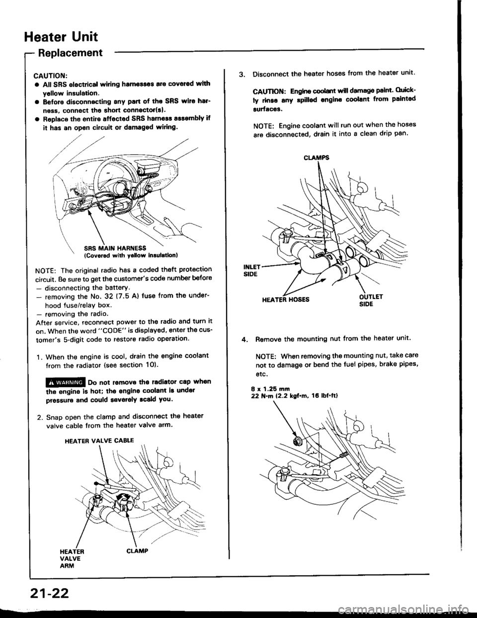
CAUTION:
a All SRS electrical witing hame$os are covoed wlth
yollow insulation.
a Before disconnecting any patt of tho SRS wito har-
neas, connect tha shott connoctol(s|.
a Roplaco th€ enlire sffacted SRS harnosr a$smbly if
it has an opon cilcult or dsmaged wiring.
NOTE: The original radio h8s a coded theft protection
circuit. Be sure to get the customer's code number betors
- disconnecting the bafterY.
- removing the No. 32 (7.5 A) fuse from th€ under-
hood tuse/relav box.- removing the radio
After service. teconnect power to the radio and turn it
on, when the word "CODE" is displayed, enter the cus-
tomer's 5-digit code to restore radio operation.
1. When the engine is cool, dtain the engine coolant
from the radiator (see section 1O).
@@ oo not lomove tho radiator cap whan
the ongine is hol; tha ongino coolant is undot
pressure and could a€voralY tcald you.
2. Snap open the clamp and disconnect the heater
valve cable from the heater valve arm.
HEATER VALVE CABLE
21-22
CLAMFS
3. Disconnect the heater hoses from the heater unit'
CAUTIOII: Engino coobnt will damago paint. orick-
ly dnse any rpilled engine coolant from paintod
surfac63.
NOTE: Engine coolant will tun out when the hoses
are disconnected, drain it into a clean drip pan'
HEATER HOSES
Remove the mounting nut from the heater unit.
NOTE: When removing the mounting nut, take care
not to damage or bend the fuel pipes, brake pipes,
etc.
8 r 1,25 rn|n22 N.m 12.2 kgt.m, tO lbf'ftl
4.
Page 1202 of 1413

lgnition
lgnition
System
Control Module (lCMl Input Test
NOTE:
a See section I 1 if the malfunction indicator lamD (MlL)
blinks.
a Pertorm an input test for the ignition control module
(lCM) after finishing the fundamental tests for the ig-
nition system and the fuel and emissions systems.
a The tachometer should operate normally.
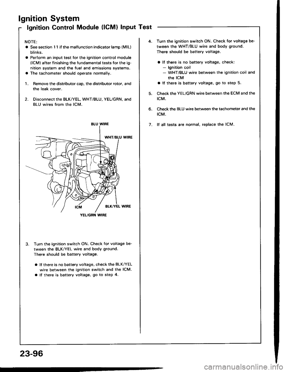
1. Remove the distributor cap, the distributor rotor, and
the leak cover.
2. Disconnect the BLK/YEL, WHT/BLU, YEL/GRN, and
BLU wires from the lCM.
3. Turn the ignition switch ON. Check for voltage be-
tween the BLK/YEL wire and body ground.
There should be battery voltage.
a lf there is no battery voltage, check the BLK^/EL
wire between the ignition switch and the lCM.
a lf there is battery voltage, go to step 4.
YEL/GRN wlRE
4.Turn the ignition switch ON. Check for voltage be-
tween the WHT/BLU wire and body ground.
There should be battery voltage.
a lf there is no battery voltage, check:- lgnition coil- WHT/BLU wire between the ignition coil and
the ICM
a lf there is battery voltage. go to step 5.
Check the YEL/GRN wire between the ECM and the
tcM.
Check the BLU wi.e between the tachometer and the
rcM.
It all tests are normal, replace the lCM.
6.
7.
23-96