Page 1158 of 1413
Fuses
Under-hood Fuse/Relay Box
ALTERI{ATOR
fTo .ngino wlto hsrno$ {Tlolll
Not usod
r: l\lot u3.d
umborAmpsColor
nF n nn46 45 /t4 35 3l
UU U UU
n32
U
n
33
U
r:rg
U
n
42
U
n43
U
[To rldidor hn r.l.Yl
Componon! (sl 01 Clrcuit 13) Protoqtod
3115 AYEL/WHTPGM-Fl main relay
327.5 AWHT/BLUECM, TCM. Clock, Stereo radio/cassette plsyer, Maintenance reminder unit
a2204BLK/REDRadiator Jan motor
34Not used
35204WHTCondenser fan motor, A/C compressor clutch
50AWHT/REDNo. I {3O A), No. 3 (7.5 A). No. 4l2O Al, No 5 (2O A), No. 7 (2O A),
No. I (20 A) fuses
3740ABLU/lVHTBlower motor
3830ABLK/GRNRear window defogger, Noise condenser
?q50AWHT/BLKlgnition switch {BAT}
4050AWHTCombination light switch, No. 17 (1O Al fuse
41100 APower distribution
4220AWHT/GRNHorn system, Brake system, Key interlock solenoid (Aff)
4310 AWHT/GRNTurn signal/hazard.elay
44Not used
45Not used
46Not used
23-52
Page 1170 of 1413
Ground Distribution
Circuit ldentification
Hstchbsckl
8r-K
BLK,lVHT-----
Pow6r door lock contolunhDriver'B door lock ectrrtorDriv6r's door lock k6y cylind6l swhchDrivor's door lock switchPowor mirroa swhch
] Pow6r window manor switch)
Ddver'3 seat bah 3whch
Fuol g&lge s€odiog unilR rl pump
Powor sntonm motorTnibr lighing conn€ctor
E
E
E
Roar wiro harnoss
Ddv6r's doorwileham63s
ABS sub-hernoss
Tailgato wirc hamoss
R6er window d6lo9g€r gro{nd wirc
@:
@:
nuo,
L Lrh I;l:. I taillisht
E Lic€nro ph6 light3
eLx -i]- BLK - Hish rDunt br.k6 tisht
BtK --------- ) ABs *nuor uni
AIY_II_ I ABS contolunh
BI.KA.VHTABS control unh
Rorr wirdow wipcr notor
Ro window d€foggor
cirt
nirt
23-64
Page 1250 of 1413
Integrated Control Unit
Circuit Diagram
D.3c ptlon
An integrat€d control unit, located in the left kick panel, integratss the functions of tho keyin/seat beh r6mind€r, sido
markar light {lasher, wiper/washer, lights-on r6minder, rear window dsfogger timer, brak€ system light bulb check, and
enging oil pressure indicator flasher circuitE,
NOTE: Difforent wires with the same color have be6n given a numbor suffix to distinguish them (for Example,
GRN/RED1 and GRN/RED'� are not the same).
WNOSHIELD WIPER/WASHER SWITCH
IMT OFFiINT
I
II
IIIIIIIIIIII
YEUEE
rl
t
P
UNOER - DASH FUS€/RETAY BOX
r NTEGRATED COI{TROI UNIT
t-0wErGrilE 0|lPRESSI'REINDICATORLIGI{T
WINDSHIELOWIPERAVASHERswtTcH
tr-/
IBLK/GRN BI
WINDSHIELOWIPERMOTOR{Asl
VOLTAGEREGULATOR{ln ahamator,
UNOER- HOOD FUSE/RELAY 8OX
I
r3
r8relit;rBt5I
23-144
lr ) : With combinod washef-wip€r oporation
Page 1253 of 1413

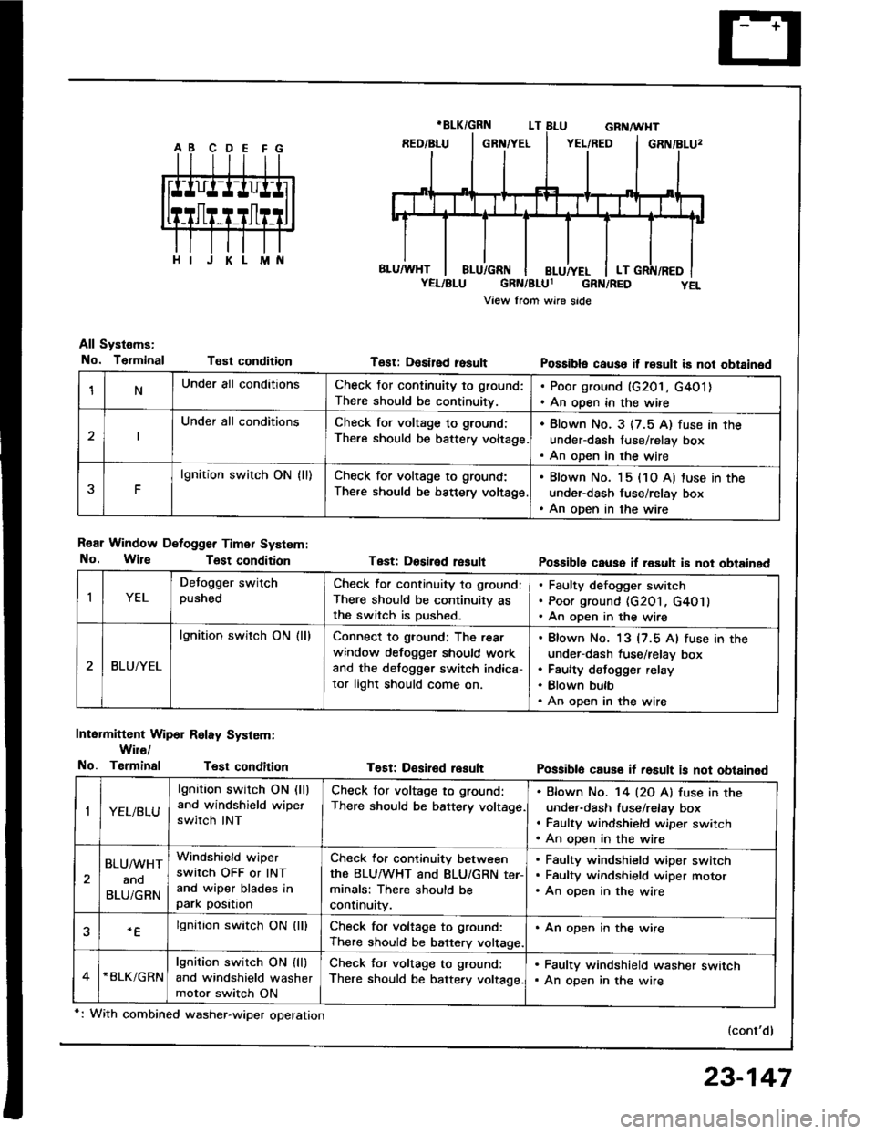
1NUnder all conditionsCheck for continuity to ground:
There should be continuitv.
. Poor ground (G201, G4O1). An open in the wire
Under all conditionsCheck for voltage to ground:
There should be battery voltage.
. Blown No. 3 (7.5 A) fuse in the
under-dash fuse/relay box. An oDen in the wire
F
lgnition switch ON {ll)Check for voltage to ground:
There should be bsttery voltage
. Blown No. 15 (10 A) tuse in the
under-dash fuse/relay box. An open in the wire
All Systems:
No. TsrminalT€st condition
R€ar Window Detogger Timer System:
No. WireTost condition
Intermittent Wip6r Relay System:
Wir€/
No. TerminalTest condition
T6st: Desired rosult
Test: Dosiled result
T€Et: Desir6d result
Possibla cause it result is not obtained
Possible cause il rosult i8 not obtained
Possiblo cause if rosult is not obtained
(cont'd)
IYEL
Defogger switchpushedCheck lor continuity to ground:
There should be continuity asthe switch is Dushed.
Faulty defogger switch
Poor ground {G201, G4O1}
An open in the wire
BLUiYEL
lgnition switch ON (ll)Connect to ground: The rear
window defogger should work
and the detogger switch indica-
tor light should come on.
Blown No. 13 {7.5 Al fuse in the
under-dash fuse/relay box
Faulty defogger relay
Blown bulb
An open in the wire
,|YEL/BLU
lgnition switch ON (ll)
and windshield wipet
switch INT
Check tor voltage to ground:
There should be battery voltage
Bfown No. '14 l2O Al fuse in the
under-dash fuse/relay box
Faulty windshield wiper switch
An oDen in the wire
BLU/WHT
ano
BLUiGRN
Windshield wiper
switch OFF or INT
and wiper blades inpark position
Check for continuity between
the BLUMHT and BLU/GRN ter-minals: There should be
continuity.
Faulty windshield wiper switch
Faultv windshield wiDer motor
An open in the wire
.Elgnition switch ON (lllCheck for voltage to ground:
There should be battery voltage.
. An open in the wire
*BLK/GRNlgnition switch ON (ll)
and windshield washer
motor switch ON
Check for voltage to ground:
There should be battery voltage.
. Faulty windshield washer switch. An open in the wire
*: With combined washer-wiper operation
23-147
Page 1276 of 1413
UNDER. HOOD FUSE/REIAY 8OX
Dash Lights Brightness Gontrol
Circuit Diagram
COMBII{ATIONLIGI{T SWTTCH
wnr-@- neorenn
REO/BLK
. GATJGE UGHTS. CruEE COITNOL DIMMING CIRCUTT. A/T GEAR POSMON N(ICATORDIMMII{G CIRCUIT' HAZAnD WARi{|NG S:WltCH LIG}fr. REAR WINOOW OEFOGGER SiWTTCH UGHT. CFUISE COMTROT MAIN S,IVITCH UGHT. A,IT GEAN POSITION CONSO|.! UGHT. HEATER COMTNOL PANEL UGHTS
TR€D
BI.K
G201G40t
23-170
UNDER- DASHFUSE/NETAY 8OX
IEF
Page 1312 of 1413
Rear Window Defogger
Component Location Index
CAUTION:
a All SRS olectrical wi ng ham€$6s are covoled with
y€llow insulation.
B6foro disconnocting any part of ths SRS wire har-
ness. connoct tho short connector(s).
Roplacs the ontire affectod SRS harness assombly if
it has an open circuit or damagcd wiring.
REAB WINDOWDEFOGGER RELAYTest, page 23-68
REAR WINDOWDEFOGGER SWITCHRemoval, page 23-209Test, page 23-2Og
REAR WINDOW DEFOGGERTest, page 23-210
UI{DER.DASH FUSE/RELAY BOX
REAR WINDOW DEFOGGER TIMER CIRCUIT
{ln the integrated control unil)fnput Test, page 23-147
SRS MAII{ HAR'{ESS
The rear window defogger is controlled by the integrated control unit, Pushing the defogger switch in the instrument
panel it sends a signal to the defogger time. in the integrated control unit, and the detogger stays on tor 25 minutes
or until the ignition switch is turned off. The indicator light in the switch comes on when the deJogger works.
23-206
Page 1314 of 1413
Rear Window Defogger
Troubleshooting
NOTE: The numbers in the table show the troubleshooting sequence.
'1: Hatchback'2: Sedan
Item to be inspected
Symptom
o
'
lD
*o--
o!
zi
ii9c
.E
o.-
:E
go
.E6
5.
o0to9\cg
o5('r6
z)
;5
o
!
ooooo
=3
oEDo
o
o
oo-
@=
g8
oo
o5
Defogger works, but indicator
light does not go on.1BLKTYEL oT BLU/YEL
Defogger does not work and
indicator light does not go on.122G201
G401YEL, BLUfYEL or BLK/YEL
Defogger does not work, but
indicstor light goes on.1423'1i G771',: G5O3
BLU|YEL or BLKIYEL
BLK/GRN oT BLKMHT
Defogger-on time is too long or
too short (normal operation time
is 25 minutes).
1
23-208
IINIilfi
Page 1316 of 1413

Rear Window Defogger
Function Test
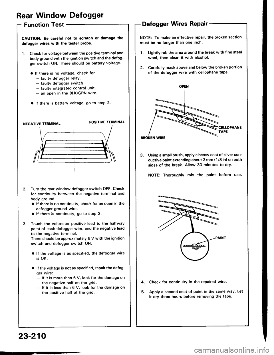
CAUTION: Be carelul not to scratch 01 damago ths
defogger wires with th€ tsster probe.
1 . Check for voltage between the positive terminal and
body ground with the ignition switch and the delog-
ger switch ON. There should be battery voltage.
a lf there is no voltage, check for
- laulty detogger relay.- faulty defogger switch.- faulty integrated control unit.- an open in the BLK/GRN wire
a lJ there is baftery voltage, go to step 2.
NEGATIVE TERMIiIALPOSITIVE TERMINAL
Turn the rear window detogger switch OFF, Check
for continuity between the negative terminal and
body ground.
a It there is no continuity, check to. an open in the
defogger ground wire.
a ll there is continuity, go to step 3.
Touch the voltmeter positive lead to the halfway
point of each defogger wire, and the negative lead
to the negative terminal.
There should be apptoximately 6 V with the ignition
switch and defogger switch ON.
a lf the voltage is as specified, the defogger wire
is OK.
a lf the voltage is not as specified. repai, the defog-
ger wire:
lf it is more than 6 V, look for the damage on
the negative half on the grid.
- lf it is less than 6 V. iook for the damage on
the positive half of the grid.
Defogger Wires Repair
NOTE: To make an eftective repair. the broken section
must be no longer than one inch.
1 . Lightly rub the area around the break with line steel
wool, then clean it with alcohol.
2. Carefullv mask above and below the broken portion
of the defogger wire with cellophane tape.
Using a small brush, apply a heavy coat of silver con-
ductive paint extending about 3 mm ( 1/8 inl on both
sides of the break. Allow 30 minutes to dry.
NOTE: Thoroughly mix the paint before use.
Check for continuity in the repaired wire.
Apply a second coat of paint in the same way.
it drv three hours betore removing the tape.
4.
OPEN
23-210
tLet