Page 107 of 1413

Timing Belt
. ReJerto page 6-51 for positioning crankshaft and pulley before installing belt.. Mark the direction of rotation on the belt before removing.
. Replace the rubber seals for oil leakage between the cylinder head and cover.. Do not use the middle cover and lower cover for storing items disassembled.
. Clean the middle cover and lower cover before installation.
lllustrated lndex
NOTE:
WASHERReplace whenCAP NUTx 1,0 mm9.8 N.m 11.0 kgf.m,7,2lbttrlor deteriorated.
CYLINDERHEAO COVERReter to page 6'78when installing.
RUBBER SEALSReplace when damagedor deteriorated,
TIMING BELTInsp€ctaon, page 6-48Adjustment. page 6-48R€placement. page 6'49
MIDDLE COVER
5xl,0mm9.8 N.m (1.0 kgt m,7.2 rbtftt
8 x 1.25 mm56 N.m 15.7 kgt m,41 tbtftl6x1.0mm9.8 N.m (1.0 kgt.m,7.2lbf ftl6x1.0mm9.8 N.m {1.0 kgl.m,7.2lbf.ftl
Installwith concavesurface lacing in.Clean.
TIMING SELDRIVE PULLEYRemove any oil and clean.
10 x 1.25 mm5a N.m 15.5 kgl.m.(} tbf.ftlFor adiustment onlydo not remove.
BOLTInstallwith concavesurface tacing out.Remove any oiland clesn.1il x 1.25 mm177 N.m 118,0 kgtm, 130lbtft)Replacement, page 6-47
COVER
PULLEYRemove any oil and cleanon the timing belt guideplate side.NOTE: When installing a new crankshaft and/or new bolt:
O tighten the crankshaft pulley bolr to 196 N.m (20.0 kgf.m. 145 lbf.ft),
@ loosen bolt,
@ retighten it to 177 N.m fl8.0 kgf.m, 130 lbnft).
3-E
6-46
Page 112 of 1413
Timing Belt
lnstallation
Install the timing belt in the feverse order of removal;
Only key points are described there.
NOTE: Clean the middle cover and lower cover before
installation.
1. Position the crankshaft and the camshaft pulleys as
shown betore installing the timing belt.
A. Set the crankshaft so that the No. 1 piston is at
top dead center {TDC). Align the groove on the
teeth side of the timing belt drive pulley to the V
pointer on the oil pump.
B. Align the TDC marks on intake and exhaust pul-
leys.
2. Install the timing belt tightly in the sequence
shown.
O Timing belt drive pulley (crankshatt) * @
Adjusting pulley * @ water pump pulley * @
Exhaust camshaft pulley * @ Intake camshaft pul-
lev,
(cont'd)
6-51
Page 126 of 1413

Camshafts
Inspection
4,
5.
9.
1.
Remove the bolts, then remove the camshaft hold-
ers from the cvlinder head.
NOTE: Unscrew the camshaft holder bolts two
turns at a time, in a crisscross pattern.
Lift camshaft out of cylinder head. wipe clean, then
inspect lift ramps. Replace camshaft if lobes are pit-
ted, scored, or excessively worn.
Clean the camshaft bearing surfaces in the cylinder
head. then set camshaft back in place.
Place a plastigage strip across each journal.
Install the camshaft holders, and then tighten the
bolts to the specified torque as shown in the left
column on this page.
NOTE: Do not rotate camshafts during inspection.
Remove the camshaft holders. Measure widest Dor-
tion of plastigage strip on each journal.
Camshaft-to-Holder Oil Clearance:
Standard {New): 0.050 - 0.089 mm
{0.002 - o.Ooil in)
Sswice Limit: 0.15 mm (0.006 in)
(cont'dl
NOTE:
. Do not rotate the camshaft during inspection.
. Remove the rocker arms and rocker shafts.
1. Put the camshafts and camshaft holders on the
cylinder head, and then tighten the bolts to the
soecified torque.
Specified Torque:
O - @: 8 mm bolts 26 N.m {2.7 kgl.m,20 lbt'ftl(D -(D:6 mm bolts 9.8 N.m {1.0 kgt.m, 7.2 lbf'ftl
Seat each camshaft by pushing it toward distributor
end of the cylinder head.
Zero the dial indicator against end of distributor
drive, then push the camshaft back and forth and
read the end play.
Camshaft End Play:
Standard (New): 0.05 - 0.15 mm
10.002 - 0.006 inl
Sawics Limit: 0.5 mm (0.02 inl
oooo@
Page 132 of 1413

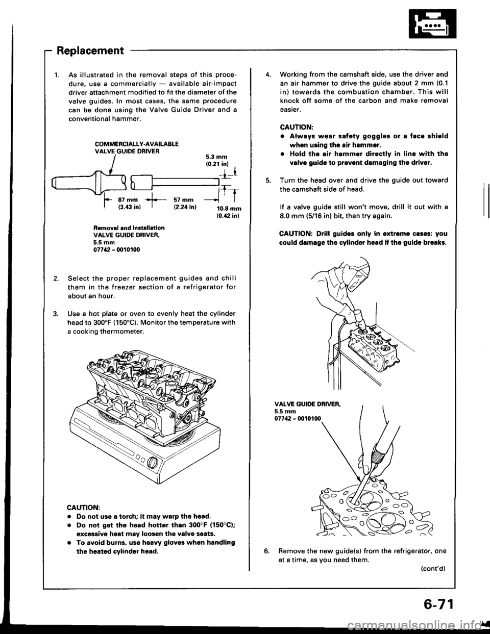
1.As illustrated in the removal steps ot this proce-
dure. use a commercially - available air-impact
driver attachment modified to fit the diameter of the
valve guides. In most cases, the same procedure
can be done using the Valve Guide Driver and a
conventional hammer,
COMMCRCIALLY.AVAILABLEVALVE GUIDE DRIVER
az mm +- sz mm{3.43 inl I tz.zt in)
tfr
10.8 mm10.42 inl
5.3 mm(0.21 inl I
_{l
R.mov.l and In3trll.tionVALVE GUIDE DRIVER.5.5 mm07742 - q)101tt0
Select the proper replacement guides and chill
them in the freezer section of a refrigerator for
about an hour.
Use a hot plate or oven to evenly heat the cylinder
head to 300'F (150"c). Monitor the temperature with
a cooking thermometer.
CAUTION:
. Do not us9 a iorch; it may warp ths hsad.
. Do not get ths head hottor than 300"F (150"C);
excsssivo hgat may loogen the valvo soaG.
. To avoid burns, use hsaw glovo3 whon handling
the heated cylindor h€ad.
Working from the camshaft side, use the driver and
an air hammer to drive the guide about 2 mm (0.1
in) towards the combustion chamber. This will
knock off some of the carbon and make removal
easier.
CAUTION:
. Always wear ssfcty gogglos 01 a taca rhiold
whcn using thc air hrmmcr,
. Hold tho.ir hammer diroctly in line with tho
v6lvo goido to prov.nt drmaging tho driv6r.
Turn the head over and drive the guide out toward
the camshaft side of head.
lf a valve guide still won't move, drill it out with a
8.0 mm (5/16 in) bit, then try again.
CAUTION; Drill guid6 only in oxtromc cs3os: you
could dlmsgo tho cylinder hoad if tho guidc brcakr.
VALVE GUIDE DBIVER.5.5 mm07742 - 0010100
6.Remove the new guide(s) from the refrigerator, one
at a time, as vou need them.(cont'd)
l o -_ -\
i oc)
Page 133 of 1413

Valve Guides
Replacement (cont'dl
7. Slip a 6 mm {0.2 in) steel washer and the correct
driver attachment over the end of the driver (The
washer will absorb some of the imDact and extendthe life of the driver).
:=:-/--PDRIVER6 mm 10.2 int ATTACHMENTWASHER
Install the new guide(s) from the camshaft side ofthe head; drive each one in until the attachment
bottoms on the head. lf you have all sixteen guides
to do, Vou may have to reheat the head one or twomore times.
Valve Guide Installed Height:
Intake: 12.55 - 13.05 mm {0.49it - 0.51it inl
Exhaust 12.55 - 13.05 mm {0.494 - 0.514 inl
VALVE GUIDE
Reaming
NOTE: For new valve guides only.
1. Coat both reamer and valve guide with cutting oil.
2, Rotate the reamer clockwise the full length of thevalve guide bore.
3. Continue to rotate the reamer clockwise whileremoving it from the bore.
4. Thoroughly wash the guide in detergent and waterto remove any cutting residue.
5. Check clearance with a valve (see page 6-70).
. Verify that the valve slides in the intake and ex-haust valve guides without exerting pressure.
REAMER HANDLE
Turn reamer inclockwise directiononry.
C'
o
a
-'{)
6-72
Page 141 of 1413

Engine Block
Speciaf Tools .............7'2
lllustrated Index ................................... 7-3
Flywheel and Drive Plate
Repfacement .........7-7
Main Bearings
Clearance ,.............. 7-8
Selection ................ 7-8
Connecting Rod Bearings
Clearance ............... 7-9
Selection ................ 7-9
Crankshaft
Removal .................7-10
End Play .................7-12
lnspection ........,,,.,,7-12
fnstallation .............7'22
Cylinder Block
Inspeetion ..............7-13
Bore Honing .....,.,,.7'14
Pistons
Inspaction ..............7-15
Installation .............7-16
Piston Rings
Replacement .........7-16
End Gap .................7-17
Ring-To-Groove C|earance,,,,.,,,...... 7 -17
Alignment ..............7-18
Piston Pins
Removal ........,........7-18
Installation (818B1 engine) ............. 7-19
fnstaffation (818C1 enginel ............. 7-20
fnspection ..............7-2O
Connecting Rods
End Play .................7-21
Sefeetion ..........,,,,,,7-22
Oil Seal
fnstaffation .............7-25
Installation
(engine removal not requiredl.. .......7-26
Page 142 of 1413
Special Tools
I
Raf. No. I Tool NumbcrDcacriptionOty I Pago Rotcrenc.
o
@
@
@
o
@
o
@
o
@
o
07GAF - PF60300
07HAF - P120102
OTLAD _ PR4O1OA
07LAF - PR30100
07LAB - PV00100 or
07924 - PD20003 or
01924 - PD20002
07948 - S800101
07749 - 0010000
07973 - PE00310
07973 - PE00320
07973 - 5570500
07973 - 6570600
Piston Pin Ease lnsert
Piston Base Head
Seal Oriver
Pilot Collar
Ring Gear Holder
Driver Attachment
Driver
Piston Pin Driver Shaft
Piston Pin Driver Head
Piston Base
Piston Base Spring
1
I
1'I
1
1
1
1
1
1
1
7-14,19,20
1-18, 19,20
7-19,20
7-1
7 -25, 26
7-19,20
1-19.20
1-18, 19, 20
1-18
Eg
o@,a\
o@
@@
0
7-2
Page 143 of 1413

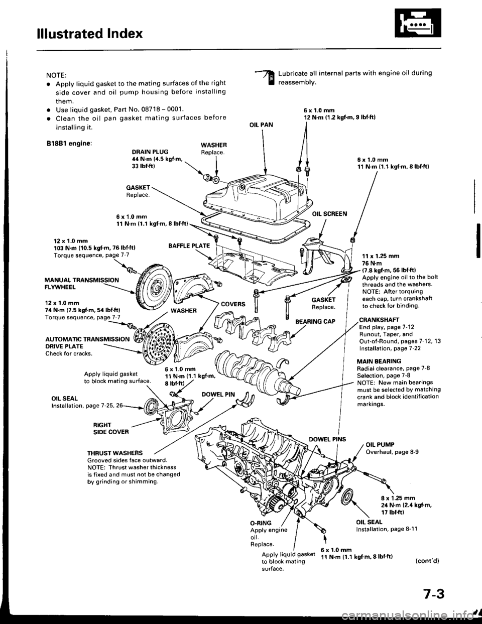
lllustrated Index
NOTE:
. Apply liquid gasket to the mating surfaces of the right
side cover and oil pump housing before installing
them.
. Use liquid gasket, Pan No.08718 - 0001.
. Clean the oil pan gasket mating surfaces before
installing it.
Bl8Bl engine: wAsHEF
Lubricate all internal parts with engine oil during
reassemory.
6x1.0mm12 N.m (1.2 kgf.m,I lbf.ftl
6x1.0mm11 N.m (1.1 kgf.m,8lbtft)
OIL SCREEN
11 x 1.25 mm76 N.m17.8 kgl.m, 56 lbf ftlApply engine oilto the bolt
threads and the washers.NOTE: After torquingeach cap, turn crankshaftto check lor binding.
DRAIN PLUG44 N.m {4.5 kgf.m,33 tbtfr)
GASKETReplace.
6x1.0mm1'l N.m {1.1 kgt.m, I lbtft)
OIL PAN
O.RING
GASKETReplace.
BEARING CAP
12 x 1.0 mm103 N.m (10.5 kgf.m, ?6lbf ft)
MANUALFLYWHEEL
'12 x 1.0 mm74 N.m {7.5 kgt m,54lbf.ftlTorque sequence, page 7 7
DRIVE PLATECheck for cracks,
AUTOMATIC TRANSMISSION
WASHER
6x1.0mm11 N.m {1.1 kgl.m,8 tbf.frt
CRANKSHAFTEnd play, page 7-12Runout, Taper, andOut-of-Round, pages 7 12, 13Instsllation, page 7 22
MAIN BEARINGRadial clearance, page 7-8
Sel€ction, page 7-8NOTE: New main bearingsmust be selected by matching
crank and block identificationmarkrngs.
Apply liquid gasket
to block mating surface.
OIL SEALInstallation, page 7-25,
RIGHTSIDE COVERDOWEL PINSOIL PUMPOverhaul, page 8-9THRUST WASHERSGrooved sides face outward.NOTE: Thrust washer thicknessis tixed and must not be changedby grinding or shamming.
8 x 1 .25 mm2,1 N.m {2.4 kgt m,17 tbt.ft)
OIL SEALInstallation, page 8-11Apply engrneorl.Replace.
Apply liquid gasket
to block mating
6x1.0mm'11 N.m {1.1 kgf'm, 8 lbl ft)(conr'dl
7-3