Page 1312 of 1413
Rear Window Defogger
Component Location Index
CAUTION:
a All SRS olectrical wi ng ham€$6s are covoled with
y€llow insulation.
B6foro disconnocting any part of ths SRS wire har-
ness. connoct tho short connector(s).
Roplacs the ontire affectod SRS harness assombly if
it has an open circuit or damagcd wiring.
REAB WINDOWDEFOGGER RELAYTest, page 23-68
REAR WINDOWDEFOGGER SWITCHRemoval, page 23-209Test, page 23-2Og
REAR WINDOW DEFOGGERTest, page 23-210
UI{DER.DASH FUSE/RELAY BOX
REAR WINDOW DEFOGGER TIMER CIRCUIT
{ln the integrated control unil)fnput Test, page 23-147
SRS MAII{ HAR'{ESS
The rear window defogger is controlled by the integrated control unit, Pushing the defogger switch in the instrument
panel it sends a signal to the defogger time. in the integrated control unit, and the detogger stays on tor 25 minutes
or until the ignition switch is turned off. The indicator light in the switch comes on when the deJogger works.
23-206
Page 1316 of 1413
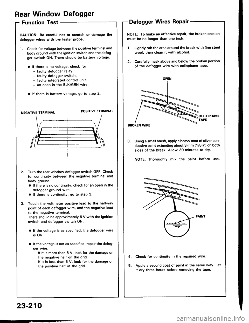
Rear Window Defogger
Function Test
CAUTION: Be carelul not to scratch 01 damago ths
defogger wires with th€ tsster probe.
1 . Check for voltage between the positive terminal and
body ground with the ignition switch and the delog-
ger switch ON. There should be battery voltage.
a lf there is no voltage, check for
- laulty detogger relay.- faulty defogger switch.- faulty integrated control unit.- an open in the BLK/GRN wire
a lJ there is baftery voltage, go to step 2.
NEGATIVE TERMIiIALPOSITIVE TERMINAL
Turn the rear window detogger switch OFF, Check
for continuity between the negative terminal and
body ground.
a It there is no continuity, check to. an open in the
defogger ground wire.
a ll there is continuity, go to step 3.
Touch the voltmeter positive lead to the halfway
point of each defogger wire, and the negative lead
to the negative terminal.
There should be apptoximately 6 V with the ignition
switch and defogger switch ON.
a lf the voltage is as specified, the defogger wire
is OK.
a lf the voltage is not as specified. repai, the defog-
ger wire:
lf it is more than 6 V, look for the damage on
the negative half on the grid.
- lf it is less than 6 V. iook for the damage on
the positive half of the grid.
Defogger Wires Repair
NOTE: To make an eftective repair. the broken section
must be no longer than one inch.
1 . Lightly rub the area around the break with line steel
wool, then clean it with alcohol.
2. Carefullv mask above and below the broken portion
of the defogger wire with cellophane tape.
Using a small brush, apply a heavy coat of silver con-
ductive paint extending about 3 mm ( 1/8 inl on both
sides of the break. Allow 30 minutes to dry.
NOTE: Thoroughly mix the paint before use.
Check for continuity in the repaired wire.
Apply a second coat of paint in the same way.
it drv three hours betore removing the tape.
4.
OPEN
23-210
tLet
Page 1320 of 1413
Moonroof
Function Test
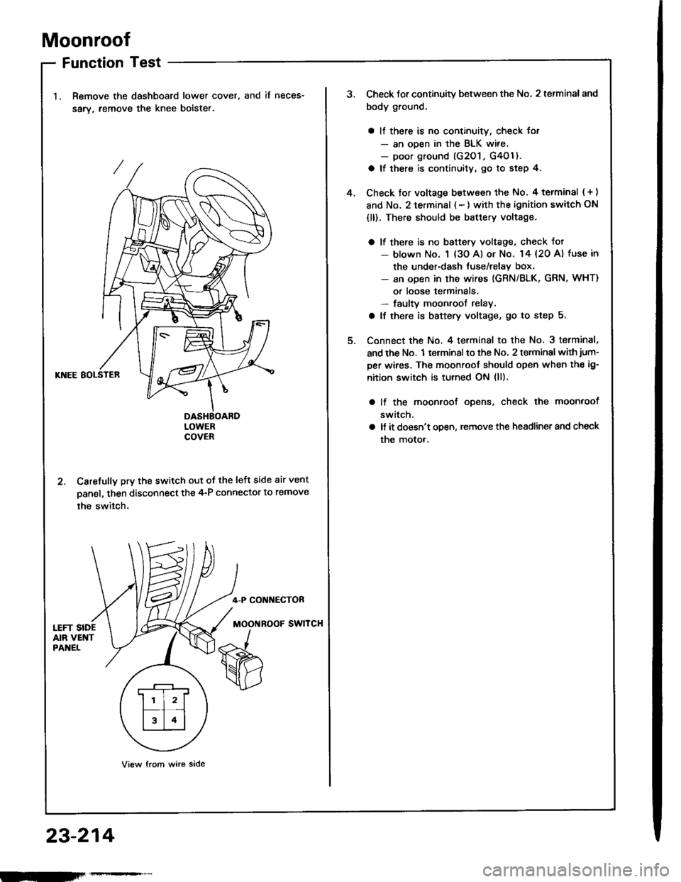
Remove the dashboard lower cover,
sarv, remove the knee bolste..
and if neces-
KNEE BOLSTER
DASHBOARDLOWERCOVER
2. Carefully pry the switch out of the left side air vent
panel, then disconnect the 4-P connector to remove
the switch.
4-P CONI{ECTOR
MOOi{ROOF SWITCH
View from wire side
.r--r
ll l2lf--T� --t
l314l
23-214
Check Jor continuity between the No. 2 terminal and
body ground.
a ll there is no continuity, check for- an ooen in the BLK wire.- poor ground (G201 , G4Ol ).
a lf there is continuity, go to step 4.
Check tor voltage between the No. 4 terminal ( + )
and No. 2 terminsl { - ) with the ignition switch ON
{ll). There should be battery voltage.
a lf there is no baftery voltage, check tot- blown No. 1 (3o Al or No. 14 {20 A) fuse in
the under-dash tuse/relay box.- an open in the wires (GRN/BLK, GRN, WHT)
or loose terminals.- faulty moonroof relay.
a lf there is battery voltage, go to step 5.
Connect the No. 4 terminal to the No. 3 terminal,
and the No. 1 terminal to the No, 2 terminal with jum-
per wires. The moonroot should open when the ig-
nition switch is turned ON (ll).
lf the moonroof ooens, check the moonroof
switch,
ll it doesn't open, remove the headlinet and check
the motor.
4.
Page 1325 of 1413
FunctionTest
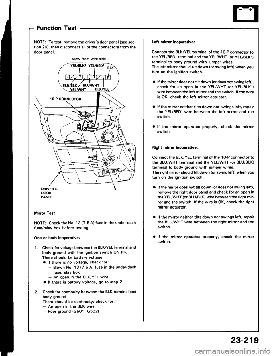
NOTE: To test, remove the driver's door panel (see sec-
tion 20), then disconnect all of the connectors from the
door oanel.
Miror Tost
NOTE; Check the No. 13 (7.5 A) tuse in the under-dash
fuse/relay box before testing.
Ono or both inop€rativa:
1. Check for voltage between the BLKIrEL terminal 8nd
body ground with the ignition switch ON (ll).
There should be battery voltage.
a lf there is no voltage, check tor:- Blown No. 13 {7.5 A) fuse in the under-dash
fuse/relav box- An ooen in the BLK/YEL wire
a It there is battery voltage, go to step 2.
2. Check for continuity between the BLK terminal and
body ground.
There should be continuity; check Jor:- An ooen in the BLK wire- Poor ground (G501, G5O2)
View from wire side
Loft mirror inopsrative:
Connect the BLK/YEL terminal of the 10-P connector to
the YEL/RED1 terminal and the YEL/WHT (or YEL/BLKr)
terminal to body ground with jumper wires.
The left mirror should tilt down (or swing leftl when you
turn on the ignition switch.
a lf the mirror does not tilt down (or does not swing leftl,
check Jor an open in the YEL/WHT (or YEL/BLK1)
wire between the left miffor and the switch. It the wir€
is OK, check the left mirror actuator.
a lf the mirro. neither tilts down nor swings left, repair
the YEL/RED1 wire between the left mirror and the
switch.
a lf the mirror operates properly, check the mirror
swatch.
Right mirror inoporative:
Connect the BLK/YEL terminal of the 1O-P connector to
th€ BLU/WHT terminal and the YEL/WHT {or BLU/BLK)
terminal to body ground with iumper wires.
The right mirror should tilt down (or swing left) when you
turn on the ignition switch.
a lf the mirror does not tilt down (or does not swing left),
remove the right door panel and check for an open in
the YELMHT (or BLU/BLK) wire between the right mir-
ror and the switch. lf the wire is OK. check the right
mtrror actualor.
a ll the mirror neither tilts down nor swings lelt, repair
the BLUMHT wire between the right mirror and the
switch.
a lf the mirror operates properly, check the mirror
swatch.
23-219
Page 1328 of 1413
Power Windows
Component LocationIndex
POWER WINDOW RELAYTest, page 23-68UI{DER-DASHFUSE/RELAY BOX
FOWER WINDOWMASTER SWITCH{Has built-in control unitlfnput Test, page 23-226, 228Tost, page 23-229, 23ORopfacement, page 23-231
FRONT PASSEI{GER'S WII{DOW SWITCHTest, page 23-230Repf acement. page 23- 231
FRONT PASSENGER'S WII{DOW MOTORfosr, page 23-232
RIGHT REAR Wll{DOW SWITCH (Sodrn}
Tost, page 23-230Replacement, page 23-231
RIGHT REAR WII{DOW
MOTOR (Sod.nl
Test, page 23-232
DBIVER'S WINDOW MOTORTest, page 23-232
LEFT REAR WINDOW MOTOB {S6dan)Test. page 23-232
LEFT REAR Wlt{DOW SWITCH lsodanlTest, page 23-230Repfacement, page 23-231
23-222
Page 1329 of 1413
UNOER-HOOO FUSE/RELAY 8OX
Circuit Diagram (Sedanl
G20rG401
UNDER_ DASH FUSE/RELAY BOX
LEFT REARWINDOWMOTORRIGHT REAN WINOOWMOTORFROI{T PASSENGER'SwrNoow i,roToRG501G502
DRiVER'S WINOOW MOTOR
23-223
Page 1333 of 1413
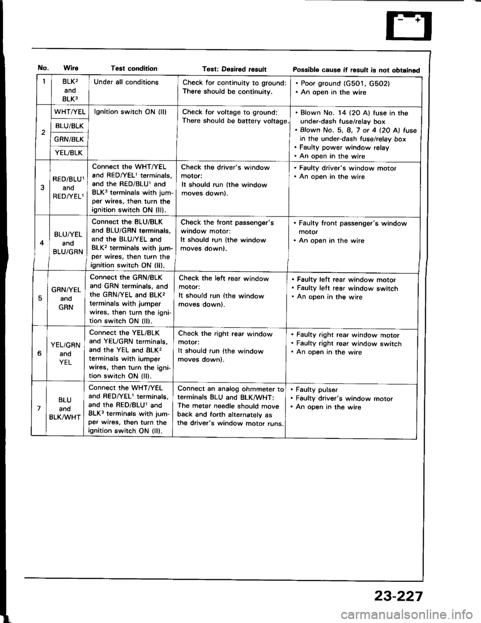
Test conditionT€st: Desirod rosultPossibl€ cause if result is not obtainad
BLK2
ano
BLK3
Under all conditionsCheck for continuity to ground:
There should be continuitv,
. Poor ground {c501, G502). An open in the wire
WHT/YELlgnition switch ON (lllCheck for voltage to ground:
The.e should be battery voltage.
Blown No. 14 (20 Al fuse in the
under-dash fuse/relay box
Bfown No. 5, 8, 7 ot 4 l2O Al fuse
in the under-dash fuse/relay box
Faulty power window relay
An open in the wire
BLU/BLK
GRN/BLK
YEL/BLK
RED/BLU1
ano
REDATELl
Connect the WHT/YEL
and RED/YEL1 terminals,
and the RED/BLU1 and
BLK3 terminals with jum-
per wires, then turn the
ignition switch ON (lll.
Check the driver's window
motor:
It should run (the window
moves down).
. Faulty drivea's window motor. An open in the wire
4
BLU/YEL
and
BLU/GRN
Connect the BLU/BLK
and BLU/GRN terminals,
and the BLU/YEL and
BLK, terminals with jum-
per wires, then turn the
ignition switch ON (ll).
Check the tront passenger's
window motor:
It should run {the window
moves down).
. Faulty front passenger's window
motOa. An open in the wire
5
GRN/YEL
ano
GRN
Connect the GRN/BLK
and GRN terminals, and
the GRN/YEL and 8LK,
terminals with iumperwires, then turn the igni-
tion switch ON (ll).
Check the left fear window
motor:
It should run (the window
moves down).
Faulty left rear window motof
Faulty lett rear window switch
An oDen in the wire
6
YEL/GRN
and
YEL
Connect the YEL/BLK
and YEL/GRN terminals,
and the YEL and BLK,
terminals with iumper
wires, then turn the igni-
tion switch ON (ll).
Check the right rear window
motor:
It should run (the window
moves down).
Faulty .ight rea. window motor
Faulty right rear window switch
An open in the wire
7
BLU
ano
BLK/VVHT
Connect the WHT/YEL
and RED/YEL1 terminals.
and the REo/BLU1 and
BLK3 terminals with jum-
per wires. then turn theignition switch ON (ll).
Conned an analog ohmmeter tote.minals BLU and BLK/wHT:
The meter needle should move
back and lorth alternatelv asthe driver's window motor runs.
Faulty pulser
Faulty driver's window motor
An open in the wire
23-227
Page 1334 of 1413
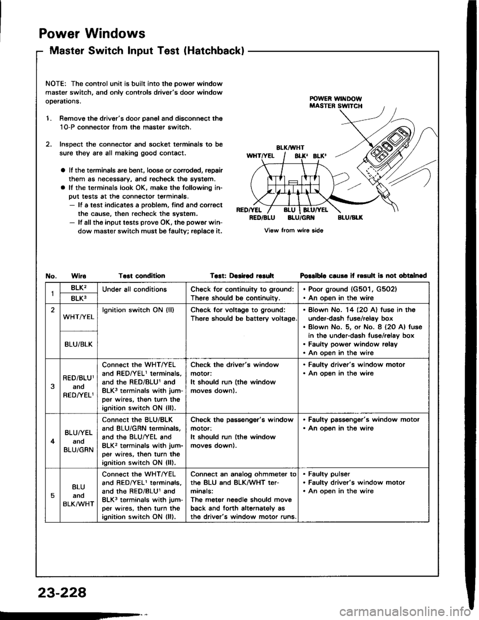
Power
Master
Windows
Switch lnput Test(Hatchback)
NOTE: The control unit is built into the power window
master switch, and onlv controls driver's door window
operations,
1. Remove the driver's door panal and disconnect the
1O-P connectol from the master switch.
2. lnsDect the connector and socket terminals to be
sure they are all making good contact.
a lf the terminsls arc bent, loose or corroded, rspair
them as necessary, and recheck the system.
a lf the terminals look OK, make the following in-
put tests at the connector terminals.- lf a test indicates a problem, find and correct
the cause, then recheck the systsm.- lf all the input tests prove OK, the powsr win-
dow master switch must be faulty; replace it.
RED/YEL
RED/BLUBLU/GR'{BLU/BLK
View from wirs sido
WiroTost conditionTost: Dashod r€suhPGslblo cluso if rosuh ir not obtalnad
1BLK'Under all conditionsCh€ck for continuity to ground:
There should be continuity.
Poor ground (G501, G5O2)
An oDen in the wire8LK3
WHT/YELlgnition switch ON {ll)Ch6ck for voltags to ground:
Th€re should be battery voltage.
Blown No. 14 l2O Al fuse in the
under-dash fuso/relay box
Blown No. 5, or No. 8 (2O A) tuse
in the under-dash luse/relay box
Faulty power window relay
An oDen in the wire
BLU/BLK
RED/BLU1
ano
RED/YELI
Connect the WHT/YEL
and REDfYELI terminals,
and the RED/BLU1 and
BLK3 terminals with jum-
per wires, then turn the
ignition switch ON {ll).
Check the driver's window
motor:
It should run (the window
moves down).
. Faulty driver's window motor. An ooen in th€ wire
4
BLU/YEL
and
BLU/GRN
Connect the BLU/BLK
and BLU/GRN terminals,
and the BLUTYEL and
BLK2 terminals with jum-
per wires, then turn the
ignition switch ON {ll).
Check ths passengor's window
motor:
It should run (the window
moves down).
. Faulty pass€nger's window motor. An oD€n in the wire
5
BLU
anq
BLKMHT
connect the WHTTYEL
and BEDrYELI terminals,
and the RED/BLU1 and
BLK3 terminals with jum-
pe. wires, then turn the
ignition switch ON (ll).
Conn€ct an analog ohmmeter to
thE BLU ANd BLKMHT t€Tr
minals:
The meter needle should move
back and torth alternately as
th€ driver's window motor runs.
Faulty pulser
Faultv driver's window motor
An oDen in the wire
23-228