1994 CADILLAC SEVILLE fuel pressure
[x] Cancel search: fuel pressurePage 194 of 399
Downloaded from www.Manualslib.com manuals search engine -
As you brake, your computer keeps receiving updates on wheel speea ana
controls braking pressure accordingly.
Remember: Anti-lock doesn’t change the time you need to get your foot
up to the brake pedal.
If you get too close to the vehicle in front of you,
you won’t have time to apply your brakes if that vehicle suddenly slows or
stops. Always leave enough room up ahead to stop, even though you have
anti-lock brakes.
To Use Anti-Lock
Don’t pump the brakes. Just hold the brake pedal down and let anti-lock
work for you. You may hear the anti-lock pump or motor operate, and
feel the brake pedal pulsate, but this is normal.
Traction Control System
Your vehicle has a traction control system that limits wheel spin. This is
especially useful in slippery road conditions. The system operates only if
it senses that one or both
of the front wheels are spinning or beginning to
lose traction. When this happens, the system works the front brakes and
reduces engine power (by shutting off fuel injectors) to limit wheel spin.
The “TRACTION ACTIVE” message will display on the Driver
Information Center when the traction control system is limiting wheel
spin. See “Driver Information Center Messages” in the Index. You may
feel the system working, or you may notice some noise, but this is normal.
If your vehicle is in cruise control when the traction control system begins
to limit wheel spin, the cruise control will automatically disengage. When
road conditions allow you to safely use it again, you may turn the cruise
control back on. (See “Cruise Control” in the Index.)
The “TRACTION DISABLED” message will display on the Driver
Information Center
if there’s a problem with your traction control system.
See “Driver Information Center Messages” in the Index. When this
message is displayed, the system will not limit wheel spin. Adjust your
driving accordingly.
181
Page 208 of 399
Downloaded from www.Manualslib.com manuals search engine Here are some things you can check before a trip:
0
0
0
0
0
e
0
Windshield Washer Fluid: Is the reservoir full? Are all windows clean
inside and outside?
Wiper Blades:
Are they in good shape?
Fuel. Engine Oil, Other Fluids; Have you checked all levels?
Lichts:
Are they all working? Are the lenses clean?
Tires: They are vitally important to a safe, trouble-free trip.
Is the
tread good enough for long-distance driving? Are the tires all inflated
to the recommended pressure?
Weather Forecasts: What’s the weather outlook along your route?
Should you delay your trip a short time to avoid a major storm
system?
Maps:
Do you have up-to-date maps?
HIGmAY HITNOSIS
Is thh Actually such a condition as “highway hypnosis”? Or is it just
plain falling asleep at the wheel? Call it highway hypnosis, lack
of
awareness, or whatever.
There is something about an easy stretch
of road with the same scenery,
along with the hum
of the tires on the road, the drone of the engine, and
the rush
of the wind against the vehicle that can make you sleepy. Don’t
let it happen to you!
If it does, your vehicle can leave the road in less than
a second, and you could crash and be injured.
What can you do about highway hypnosis? First, be aware that it can
happen.
Then here are some tips:
Make sure your vehicle is well ventilated, with a comfortably cool
interior.
Keep your eyes moving. Scan the road ahead and to the sides. Check
your rearview mirrors and your instruments frequently.
If you get sleepy, pull off the road into a rest, service, or parking area
and take a nap, get some exercise, or both. For safety, treat drowsiness
on the highway as an emergency.
195
Page 260 of 399
Downloaded from www.Manualslib.com manuals search engine -
The test used to determine me city fuel economy estimate simulates a
7.5 mile
(12 km), stop and go trip with an average speed of 20 mph
(32 km/h). The trip takes 23 minutes and has 18 stops. About one fifth
of the time is spent idling, as in waiting at traffic lights or in rush hour
traffic. Two kinds
of engine starts are used: a cold start, which is similar to
starting a car in the morning after it has been parked all night and a hot
start, which is similar to restarting
a vehicle after it has been warmed up,
driven and stopped for a short time.
The test used to determine the highway fuel economy estimate represents
a mixture
of “non-city” driving. Segments corresponding to different
kinds of rural roads and interstate highways are included. The test
simulates a
10 mile (17 km) trip with an average speed of 48 mph
(77
km/h). The test is run from a hot start and has little idling time and
no stops.
To assure that the fuel economy numbers are most useful for consumers,
the EPA adjusts these laboratory test results to account for the difference
between controlled laboratory conditions and actual driving on the road.
The laboratory fuel economy results are adjusted downward to arrive at
the estimates on the fuel economy window sticker and the Gas Mileage
Guide. The
city estimate is lowered by 10 percent and the highway
estimate is lowered by
22 percent from the laboratory test results.
Experience has proven that these adjustments make the mileage
estimates correspond more closely to the actual fuel economy realized by
the average driver.
Even though these figures are adjusted, they still represent what the
average driver will get. Your fuel economy may be significantly higher or
lower, depending on how, when, and where your vehicle is driven. Here
are some things you can do to increase fuel economy;
Combine errands into one trip.
Turn the engine off rather than letting it idle for more than a minute.
Have your Cadillac serviced as described in the maintenance booklet.
Keep tires inflated to recommended pressures.
0 Anticipate traffic stops.
247
Page 304 of 399
Downloaded from www.Manualslib.com manuals search engine r
f
r
r I 1
i- I
NOTICE:
Don’t let anyone tell you that underidlation or overinflation is
all right. It’s not. If your tires don’t have enough air
(underinflation) you can get:
Too much flexing
Too much heat
Tire overloading
Bad wear
Bad handling
Bad fuel economy.
If your tires have
too much air (overinflation), you can get:
Unusual wear
Bad handling
Rough ride
Needless damage from road hazards.
7 I
!
-
I
How to Check Use a good quality pocket-type gage to check tire
pressure. Simply looking at the tires will not tell you the pressure,
especially if you have radial tires
-- which may look properly inflated even
if they’re underinflated.
If your tires have valve caps, be sure to put them back on. They help
prevent leaks by keeping out dirt and moisture.
When to Check Check your tires once a month or more.
The
SLS tire pressures are:
Front - 28 psi (190 kPa)
Rear - 26 psi (180 Pa)
SLS recommended tire size is:
Michelin XW4 Blackwall (P225/60R16)
291
Page 325 of 399
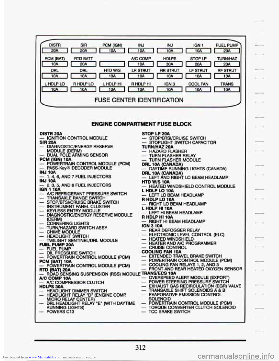
Downloaded from www.Manualslib.com manuals search engine DISTR PCM (IGN) IGN 1
, PC';":"), RTD BATT
~-1nmmmrl
A/C COMP HDLPS STOP LP TURNIHAZ
HTD
W/S LR STRUT RR STRUT LF STRUT RFSTRUT
LHDLPLO RHDLPLO LHDLPHI RHDLPHI
IGN
3 COOL FAN TRANS
~mmmrnmm~
FUSE CENTER IDENTIFICATION I
ENGINE COMPARTMENT FUSE BLOCK
DISTR 20A
SIR 20A - IGNITION CONTROL MODULE
- DIAGNOSTIC/ENERGY RESERVE
- DUAL POLE AR d ING SENSOR
MODULE (DERM PCM
(ION 1OA - PowEATmIN CONTROL MODULE - PASS-KevB DECODER MODULE INJ 1OA
- 1,4,6, AND 7 FUEL INJECTORS
- 2,3,5, AND 8 FUEL INJECTORS
- - - - - __ -
INJ 1OA
ION 1 1OA
- NC REFRIGERANT PRESSURE SWITCH ~~ ~
- TRANSAXLE RANGE SWITCH - STOP/BTSI/CRUISE BRAKE SWITCH - INSTRUMENT PANEL CLUSTER - KEYLESS ENTRY MODULE - DIAGNOSTWENERGY RESERVE MODULE
FERMl ~ ~. - ORN RING LIGHTS
- TURN/HAZARD SWITCH ASSY - CHIME MODULE - HEADLIGHT SWITCH - mlUGHT SEUTINEUDRL MODULE FUEL PUMP 20A
STOP LP 20A - STOP/BTSI/CRUISE SWITCH - STOPLIGHT SWITCH CAPACITOR TURN/HAZ 20A - HAZARD FLASHER - TURN FLASHER RELAY - TURN FLASHER MODULE ~ ~~ ~ ~~ DRL 1 OA (CANADA)
DRL 1OA (CANADA)
HTD
W/S 1OA
- DAMIME RUNNING LIGHTS (CANADA)
- LEFT AND RIGHT LO BEAM HEADLAMP
- HEATED WINDSHIELD CONTROL MODULE L HDLP LO 10A
R HDLP LO 1OA - LEFT LO BEAM HEADLAMP
- RIGHT LOBEAM HEADLAMP L HDLP HI 10A
R HDLP HI 1OA - LEFT HI BEAM HEADLAMP
- RIGHT HI BEAM HEADLAMP ION 3 -1 OA - REAR DEFOGGER RELAY - ELECTRONIC LEVEL CONTROL (ELC) - HEATED WINDSHIELD - HEATER AND A/C PROGRAMMER
COOLING FAN 10A - CRUISE CONTROL
- EXTENDED TRAVEL BRAKE SWITCH - POWERTRAIN CONTROL MODULE (PCM) - COOLING FAN RELAYS 1.2. AND 3
- PUMP^
- OIL PRESSURE SWITCH - POWERTRAIN CONTROL MODULE (PCM)
- POWERTRAIN CONTROL MODULE (PCM) PCM (BAT) 1OA
RTD BAT) 20A - FRONT AND REAR HEATED-OXYGEN SENSOR
A/C COMP 10A
HDLPS 3OA - EXHAUST GAS RECIRCULATION (EGR) VALVE
- SENSING SUSPENSlON (RSS) MODULE MODULE (EXPORT)
- NC COMPRESSOR CLUTCH - POWER STEERING PRESSURE SWITCH
- HEADLIGHT DIMMER SWITCH - TRANSAXLE SHIFT SOLENOIDS A & B - HEADLIGHT RELAY "D" (ENGINE COME - EVAPORATIVE EMISSION CONTROL
- DRL HEADLIGHT RELAY "E" (WITH DAYTIME - POWERTRAIN CONTROL MODULE (PCM)
- POWERS C13 - TCC BRAKE SWITCH
MICRO RELAY CENTER)
SOLENOID
RUNNING LIGHTS) - TORQUE CONVERTER CLUTCH SOLENOID
312
Page 326 of 399
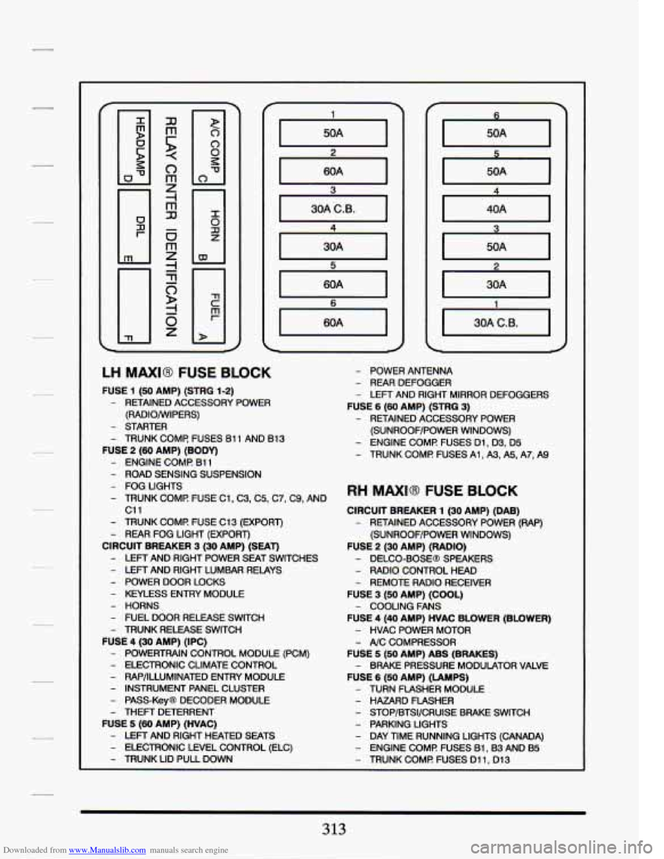
Downloaded from www.Manualslib.com manuals search engine 60A I
LH MAXI8 FUSE BLOCK
FUSE 1 (50 AMP) (STRG 1-2)
- RETAINED ACCESSORY POWER
(RADIO/WIPERS)
- STARTER
- TRUNK COMF! FUSES 61 1 AND 81 3
FUSE 2 (60 AMP) (BODY)
- ENGINE COMI? B11
- ROAD SENSING SUSPENSION
- FOG LIGHTS
- TRUNK COMI? FUSE C1, C3, C5, C7, C9, AND
c11
- TRUNK COME FUSE C13 (EXPORT)
- REAR FOG LIGHT (EXPORT)
CIRCUIT BREAKER 3 (30 AMP) (SEAT)
- LEFT AND RIGHT POWER SEAT SWITCHES
- LEFT AND RIGHT LUMBAR RELAYS
- POWER DOOR LOCKS
- KEYLESS ENTRY MODULE
- HORNS
- FUEL DOOR RELEASE SWITCH
- TRUNK RELEASE SWITCH
FUSE 4 (30 AMP) (IPC)
- POWERTRAIN CONTROL MODULE (PCM)
- ELECTRONIC CLIMATE CONTROL
- W/ILLUMINATED ENTRY MODULE
- INSTRUMENT PANEL CLUSTER
- PASS-Key@ DECODER MODULE
- THEFT DETERRENT
FUSE 5 (60 AMP) (HVAC)
- LEFT AND RIGHT HEATED SEATS
- ELECTRONIC LEVEL CONTROL (ELC)
- TRUNK LID PULL DOWN
- POWER ANTENNA
- REAR DEFOGGER
- LEFT AND RIGHT MIRROR DEFOGGERS
FUSE 6 (60 AMP) (STRQ 3)
- RETAINED ACCESSORY POWER
(SUNROOF/POWER WINDOWS)
- ENGINE COMI? FUSES Dl, 03, D5
- TRUNK COMI? FUSES A1 , A3, A5, A7, A9
RH MAXI@ FUSE BLOCK
CIRCUIT BREAKER 1 (30 AMP) (DAB)
- RETAINED ACCESSORY POWER (RAP)
(SUNROOF/POWER WINDOWS)
FUSE 2 (30 AMP) (RADIO)
- DELCO-BOSEB SPEAKERS
- RADIO CONTROL HEAD
- REMOTE RADIO RECEIVER
FUSE 3 (50 AMP) (COOL)
FUSE
4 (40 AMP) HVAC BLOWER (BLOWER)
- COOLING FANS
- HVAC POWER MOTOR
- A/C COMPRESSOR
FUSE 5 (So AMP) ABS (BRAKES)
FUSE
6 (So AMP) (LAMPS)
- BRAKE PRESSURE MODULATOR VALVE
- TURN FLASHER MODULE
- HAZARD FLASHER
- STOP/BTSI/CRUISE BRAKE SWITCH
- PARKING LIGHTS
- DAY TIME RUNNING LIGHTS (CANADA)
- ENGINE COMI? FUSES Bl,B3 AND B5
- TRUNK COMI? FUSES Dl 1, Dl3
313
Page 332 of 399
Downloaded from www.Manualslib.com manuals search engine The Northstar engine is designed to minimize the need for routine
maintenance while incorporating systems to remind the driver when
service is required.
An oil life index indicator monitors ongoing operating
conditions and reminds the driver when an oil change is needed.
A low
coolant warning message keeps track of the level of this vital fluid. Direct
acting hydraulic tappets provide maintenance free zero lash operation of
the
32 valves from idle to the 6500 rpm redline. The camshafts are driven
by a
two stage roller chain assembly which is designed to provide quiet
maintenance free operation. Platinum tipped spark plugs increase the
replacement interval to
100,OO miles.
The four valves per cylinder design provides more efficient engine
breathing, resulting in higher power than comparable
two valve engines.
The induction system uses smooth thermoplastic tubes
to channel air into
the cylinders. These smooth tubes simulate the elaborate port polishing
methods used on racing engines. The shape and length
of the tubes
boosts horsepower by using sonic pressure waves created by the motion of
the inlet valves to increase the amount
of air entering each cylinder. Once
the intake charge has entered the cylinder, the centrally located spark
plug ensures fast and efficient burning of the fuel/air mixture.
This engine is designed to be very durable. The aluminum block has
cast-in-place iron cylinder liners for greater wear resistance. High
strength connecting rods support the
free floating piston pins in bronze
bushings for superior high speed performance.
The fillets of the nodular
iron crankshaft undergo a high pressure compression rolling operation to
improve their resistance to fatigue.
Quiet operation is enhanced by the use
of special materials and designs.
The front cover of the engine is stamped from laminated steel which
damps out noise. Special cam cover gasket seals isolate va1v.e train
operation. The fuel injectors are placed inside the induction system
housing to eliminate the clicking noise which
is common to other fuel
injected engines.
The Northstar engine is designed to provide years
of efficient, reliable,
satisfying operation.
319
Page 338 of 399
Downloaded from www.Manualslib.com manuals search engine Right Bank ......................................... 1-3-5-7
Camshaft
................... Induction Hardened Cast Grey Iron
Drive Type
........ Single Row / Staged Drive 8 mm Roller Chain
Main Bearings
......................................... Five
ENGINE LUBRICATION SYSTEM
Type of Intake ..................................... Stationary
Filter System
...................................... Full-Flow
ENGINE COOLING SYSTEM
Surge Tank Cap Relief Pressure ............... 15.0 psi (103 kPa)
Water Pump
Type ................................. Centrifugal
Drive Belt
....................................... Serpentine
Radiator Core
................................... Aluminum
Radiator Cooling Fans (2)
............................ Electric
Thermostat Starts
To Open
................ 192-199°F (89-93 "C)
FUEL SYSTEM
Induction Type ............ Sequential Port Fuel Injection (SPFI)
System Pressure .................... .33.4-43.5 psi (230-300 kPa)
Idle Speed
.................................. ECM Controlled
Filter Type
............................... Paper Type Element
Fuel Pump
................................. Electric (In Tank)
Fuel Required
................. Premium Unleaded (91 Octane)
AUTOMTIC TRANSAXZE
SLS (Trade Name ) ....................... Hydra- Matic 4TSOE
Type
..................................... 4-Speed Automatic
.................................... Viscous Converter Clutch
STS (Trade Name
) ....................... Hydra- Matic 4T80E
Type ..................................... 4-Speed Automatic
.................................... Torque Converter Clutch
325