Page 31 of 80

LED Status (Keys equipped with LED):
The following functions can be checked with the LED:
• Flashing LED when pressing a button.
Indicates that the data is being transmitted.
(battery voltage between 3.2 - 2.6 volts)
• No LED activity when pressing a button:
1. ZKE responds to pressed button only to
unlock a locked vehicle. Indicates the bat-
tery is between 2.6 - 2.2 volts. Replace bat-
tery.
2. No unlock of vehicle. Indicates battery is
below 2.2 volts. Replace battery.
FZV Key Test: Pressing the trunk release and lock buttons together activates the key test. If
the battery and FZV key EEPROM are “OK”, the LED will come ON for approximately 1 sec-
ond.
FZV Key Rechargeable Battery
From KL R, the battery inside the key head is charged inductively by the EWS ring antenna
via a coil antenna integrated in the key. The charging process is controlled by electronic
circuitry integrated in the key.
• The service life of a radio-control key used under normal conditions corresponds to the veh-
icle lifespan.
• If the FZV keys are not used (ie: stored in a drawer), the battery will be discharged after
approx. 1.5 years.
• The time required to fully charge a discharged battery is approx. 30 hours.
• The remote control can be operated about 15 times after a charging period of approx. 30
minutes (driving time).
31
Central Body Electronics ZKE III
Page 32 of 80

The key data is stored in a transponder chip. The transponder chip is a wireless read and
write EEPROM. It is powered via the ring coil at the steering lock. Power is applied elec-
tromagnetically when the key is in the ignition switch from KL R.
The power supply is used both for data transfer as well as for charging the battery. This has
been made possible by new development of the transponder chip.
As with previous systems, every press of an FZV key also provides the battery charge con-
dition. When the FZV electronics receives a low power condition message three successive
times, the GM sets a fault indicating a low battery within a specific key. The LCM is also
informed via the bus system and alerts the driver via an instrument cluster matrix message.
If the battery is recharged (used operate car), the fault will be automatically deleted when
five successive messages are received indicating a charged battery condition.
The battery has no affect on the EWS III communication function!
32
Central Body Electronics ZKE III
Page 69 of 80

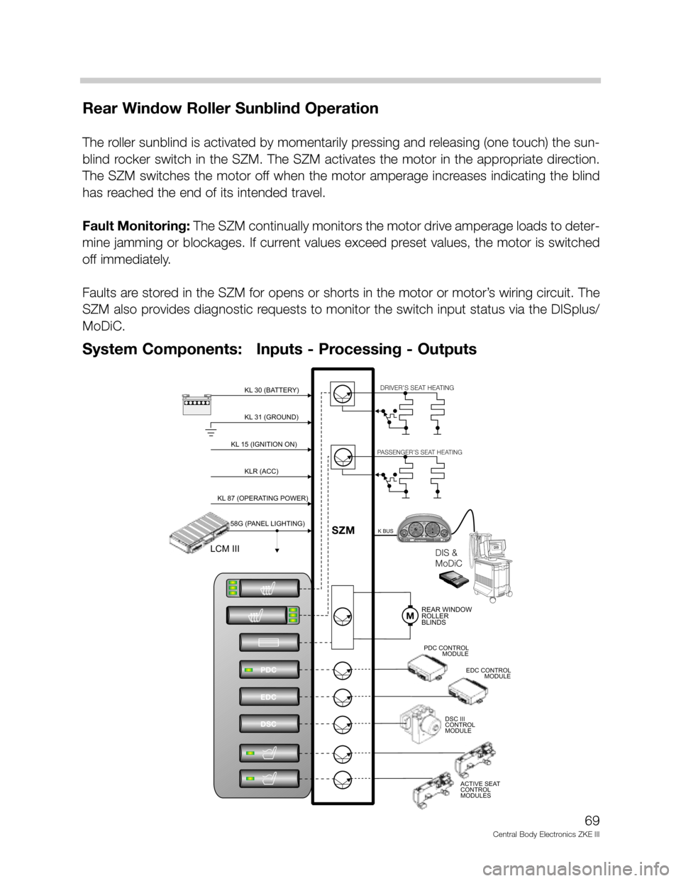
Rear Window Roller Sunblind Operation
The roller sunblind is activated by momentarily pressing and releasing (one touch) the sun-
blind rocker switch in the SZM. The SZM activates the motor in the appropriate direction.
The SZM switches the motor off when the motor amperage increases indicating the blind
has reached the end of its intended travel.
Fault Monitoring: The SZM continually monitors the motor drive amperage loads to deter-
mine jamming or blockages. If current values exceed preset values, the motor is switched
off immediately.
Faults are stored in the SZM for opens or shorts in the motor or motor’s wiring circuit. The
SZM also provides diagnostic requests to monitor the switch input status via the DISplus/
MoDiC.
69
Central Body Electronics ZKE III
KL 31 (GROUND)KL 31 (GROUND)
DIS
DIS
BMWDIS
B
M
WD
I
S
BMWDIS
BMW
DIS
D
ia
g
n
o
s
e
-
a
n
d
In
fo
r
m
a
ti
o
n
S
y
s
t
e
mDIS &
MoDiCDIS &
MoDiC
M
o
Di
C
0½
CHECK
ENGINE
CHECK
ENGINEOIL SERVICEOIL SERVICEINSPECTIONINSPECTIONP
1/min
x1000km/hELECTRONICMPH1
2020404060608080100180160140 1201002001202201402400234
5
6
7!!ABS20 DIGIT READOUT20 DIGIT READOUT
123456
prnd432
m
prnd432
m
122.4 +72.0 fo
+72.0 fomiles0
10
15 20 40
KL 30 (BATTERY)KL 30 (BATTERY)-+
KL 15 (IGNITION ON)KL 15 (IGNITION ON)
KLR (ACC)KLR (ACC)
KL 87 (OPERATING POWER)KL 87 (OPERATING POWER)
58G (PANEL LIGHTING)58G (PANEL LIGHTING)
LCM IIILCM III
PDC
EDC
DSC
MREAR WINDOW
ROLLER
BLINDSREAR WINDOW
ROLLER
BLINDS
DRIVER’S SEAT HEATINGDRIVER’S SEAT HEATING
PASSENGER’S SEAT HEATINGPASSENGER’S SEAT HEATING
K BUSK BUS
PDC CONTROL
MODULEPDC CONTROL
MODULE
EDC CONTROL
MODULEEDC CONTROL
MODULE
SZMSZM
DSC III
CONTROL
MODULEDSC III
CONTROL
MODULE
ACTIVE SEAT
CONTROL
MODULESACTIVE SEAT
CONTROL
MODULES
System Components: Inputs - Processing - Outputs
Page 72 of 80

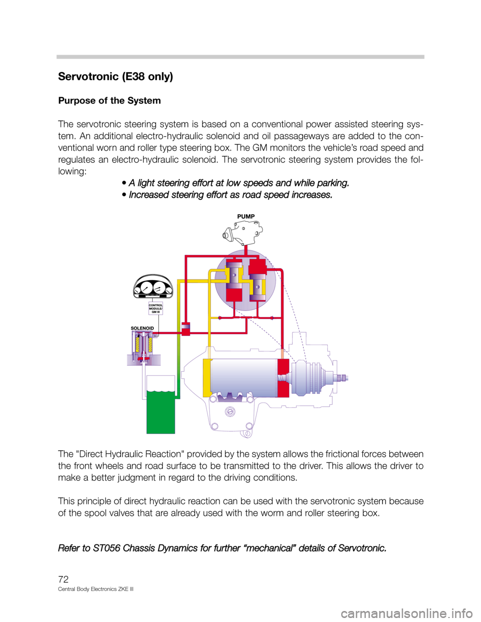
Servotronic (E38 only)
Purpose of the System
The servotronic steering system is based on a conventional power assisted steering sys-
tem. An additional electro-hydraulic solenoid and oil passageways are added to the con-
ventional worn and roller type steering box. The GM monitors the vehicle’s road speed and
regulates an electro-hydraulic solenoid. The servotronic steering system provides the fol-
lowing:
• A light steering effort at low speeds and while parking.
• Increased steering effort as road speed increases.
The "Direct Hydraulic Reaction" provided by the system allows the frictional forces between
the front wheels and road surface to be transmitted to the driver. This allows the driver to
make a better judgment in regard to the driving conditions.
This principle of direct hydraulic reaction can be used with the servotronic system because
of the spool valves that are already used with the worm and roller steering box.
Refer to ST056 Chassis Dynamics for further “mechanical” details of Servotronic.
72
Central Body Electronics ZKE III
Page 73 of 80

System Components
Electro-Hydraulic Solenoid: The solenoid regulates the
amount of power steering assist for the servotronic system. It
contains a needle valve that can restrict oil flow. When current
is applied, the needle valve closes against spring pressure to
restrict the oil flow.
With maximum current applied, the valve is closed. This is the
condition of the valve for slow speed driving and parking.
Without current applied, the needle valve is held open by
spring pressure. This is the condition of the solenoid during
higher driving speeds.
Electro-Hydraulic Solenoid Control: The GM monitors the road speed input and sup-
plies the electro-hydraulic solenoid with power. The road speed signal “A” is supplied from
the IKE (and K-Bus) on E38 vehicles and from the DSC Control Module on E39/E53 vehi-
cles.
The solenoid is pulse width modulated for control and varies the amount of assist based
on the road speed. The maximum assist is available while parking and driving at slow
speeds.
73
Central Body Electronics ZKE III