Page 63 of 80

Passenger’s Seat (without memory)
Principle of Operation
The passenger seat control switch is purely a mechanical switching module that activates
the passenger seat motors without position monitoring capabilities. Due to the limited op-
eration requirements, the passenger seat control switch is not equipped with on board
diagnostics.
The Passenger Seat control switch is equipped with an overload protection function. If
excessive amperage is drawn due to a defective motor or a switch is stuck driving a motor
to the end limit, the function activates opening the motor control circuit.
Passenger Seat Motors: Each motor is individually controlled by the Seat Control Switch.
Each position motor is connected to the seat position switch by a two wire circuit provid-
ing motor activation in both directions (no position recognition).
Passenger Seat Adjustment: Operation of the passenger seat is always possible regard-
less of the ignition key position. Moving a position switch operates a the motor control con-
tacts directly, the switch applies voltage and ground path directly to operate the motor.
Reversing the switch simply changes the motor polarity. More than one passenger seat
motor can be run simultaneously.
Optional Seat Back Lumbar Support
The optional air bladder lumbar support system is similar in all
vehicles (if equipped). Each seat contains the following com-
ponents:
• Four position circular rocker switch in the seat base trim in
the area of the seat switches.
• Electrically controlled air compressor with over pressure cut
out under each seat.
• Two solenoid activated air controlling valve blocks (one per
air bladder). Each valve block includes an inlet and an outlet
valve. When energized they direct air into the bladder(s) to
inflate or relieve trapped air to deflate the bladders.
• Connecting hoses and air bladders in lower seat back.
63
Central Body Electronics ZKE III
Page 64 of 80

Principle of Operation
The lumbar support system can be operated at any time regardless of key position. The
four position circular rocker switch provides power switching to operate the system as fol-
lows:
• Position 1: The internal switch contacts provide a power and ground path for both valve
block inlet valves and the air compressor. Both bladders inflate until the switch is
released. If the switch is held continuously, an overpressure bypass valve opens on the
compressor preventing damage to the bladders.
• Position 2: Compressor activated, upper bladder inflates, lower bladder deflates.
• Position 3: Compressor activated, lower bladder inflates, upper bladder deflates.
• Position 4: Compressor is not activated. Upper and Lower bladders both deflate.
This function is not stored in memory for recall.
Diagnosis
The seat lumbar support system is purely electro-pneumatic control system. No electron-
ic diagnostic communication is possible.
64
Central Body Electronics ZKE III
Page 66 of 80

Principle of Operation
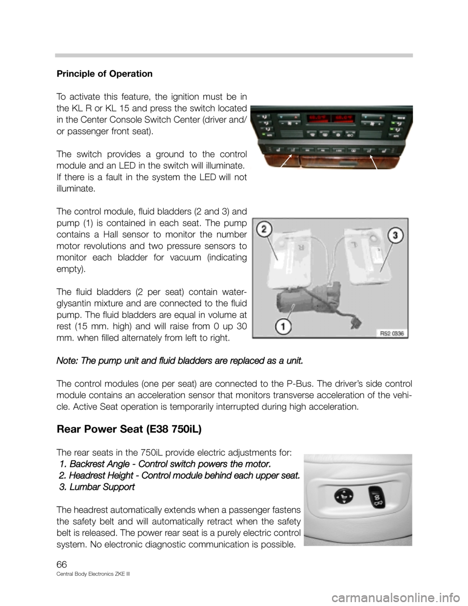
To activate this feature, the ignition must be in
the KL R or KL 15 and press the switch located
in the Center Console Switch Center (driver and/
or passenger front seat).
The switch provides a ground to the control
module and an LED in the switch will illuminate.
If there is a fault in the system the LED will not
illuminate.
The control module, fluid bladders (2 and 3) and
pump (1) is contained in each seat. The pump
contains a Hall sensor to monitor the number
motor revolutions and two pressure sensors to
monitor each bladder for vacuum (indicating
empty).
The fluid bladders (2 per seat) contain water-
glysantin mixture and are connected to the fluid
pump. The fluid bladders are equal in volume at
rest (15 mm. high) and will raise from 0 up 30
mm. when filled alternately from left to right.
Note: The pump unit and fluid bladders are replaced as a unit.
The control modules (one per seat) are connected to the P-Bus. The driver’s side control
module contains an acceleration sensor that monitors transverse acceleration of the vehi-
cle. Active Seat operation is temporarily interrupted during high acceleration.
Rear Power Seat (E38 750iL)
The rear seats in the 750iL provide electric adjustments for:
1. Backrest Angle - Control switch powers the motor.
2. Headrest Height - Control module behind each upper seat.
3. Lumbar Support
The headrest automatically extends when a passenger fastens
the safety belt and will automatically retract when the safety
belt is released. The power rear seat is a purely electric control
system. No electronic diagnostic communication is possible.
66
Central Body Electronics ZKE III