1994 BMW 325i electrical
[x] Cancel search: electricalPage 456 of 759

640-10
HEATING
AND
AIR
CONDITIONING
i
El
Radio
Antenna
Rear
.
,
si,-
Left
side
I
d
1
.
Rear
vents
2
.
Fresh
air
3
.
Face-level
vents
4
.
Recirculation
5
.
Footwell
vents
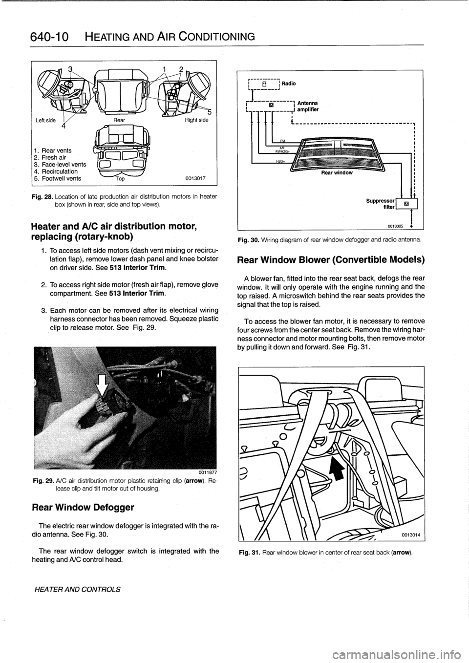
0013017
Fig
.
28
.
Location
oflate
production
air
distribution
motors
in
heater
box(shown
in
rear,
side
and
top
views)
.
Heater
andA/C
air
distribution
motor,
replacing
(rotary-knob)
1
.
Toaccess
left
side
motors
(dash
vent
mixing
or
recircu-
lation
flap),
remove
lower
dash
panel
and
knee
bolster
on
driver
side
.
See
513
Interior
Trim
.
2
.
To
access
right
side
motor
(fresh
air
flap),
remove
glove
compartment
.
See513
Interior
Trim
.
3
.
Each
motor
can
be
removed
after
its
electrical
wiring
harness
connector
has
been
removed
.
Squeeze
plastic
clip
to
release
motor
.
See
Fig
.
29
.
Fig
.
29
.
A/
C
air
distribution
motor
plastic
retaíning
clip
(arrow)
.
Re-
lease
clip
and
tilt
motor
out
of
housing
.
Rear
Window
Defogger
0011877
The
rear
window
defogger
switch
is
integrated
with
the
heating
andA/C
control
head
.
HEATER
AND
CONTROLS
Fig
.
30
.
Wiring
diagram
of
rear
window
defogger
and
radio
antenna
.
Rear
Window
Blower
(Convertible
Models)
A
blower
fan,
fitted
into
the
rear
seatback,
defogs
therear
window
.
It
will
only
operate
with
the
engine
nunning
and
the
top
raised
.
A
microswitch
behindthe
rear
seats
provides
the
signal
that
thetop
is
raised
.
To
access
the
blower
fan
motor,
it
is
necessary
to
remove
four
screwsfrom
the
center
seat
back
.
Remove
the
wiring
har-
ness
connector
and
motor
mounting
boits,
then
remove
motor
by
pulling
it
down
and
forward
.
See
Fig
.
31
.
ri
Suppressor
filter
1
0013005
Fig
.
31
.
Rear
window
blower
in
center
of
rear
seat
back
(arrow)
.
The
electric
rear
window
defogger
is
integrated
with
the
ra-
dio
antenna
.
See
Fig
.
30
.
y
/f
0013014
Page 459 of 759

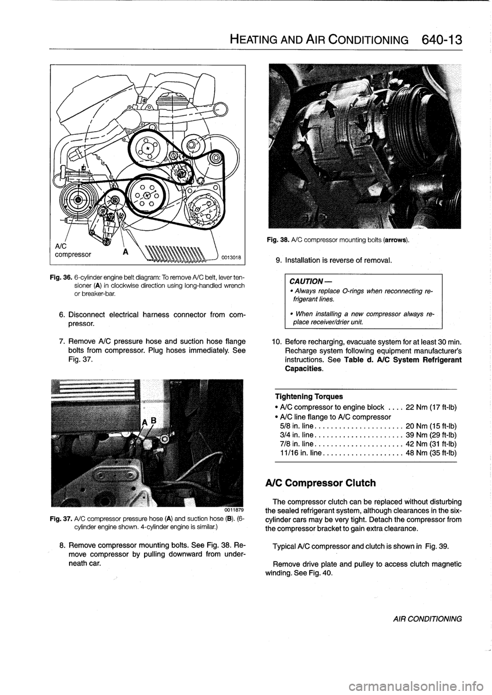
Fig
.
36
.
6-cylinder
engine
belt
diagram
:
To
remove
A/C
belt,
lever
ten-
sioner
(A)
in
clockwise
direction
using
long-handled
wrench
or
breaker-bar
.
6
.
Disconnect
electrical
harness
connector
from
com-
pressor
.
7
.
Remove
A/C
pressure
hose
and
suction
hose
flange
10
.
Before
recharging,
evacuate
system
for
at
least
30
min
.
bolts
from
compressor
.
Plug
hoses
immediately
See
Recharge
system
following
equipment
manufacturer's
Fig
.
37
.
instructions
.
See
Table
d
.
A/C
System
Refrigerant
Capacities
.
0011879
Fig
.
37
.
A/
C
compressor
pressure
hose
(A)
and
suction
hose
(B)
.
(6-
cylinder
engine
shown
.
4-cylinder
engine
is
similar
.)
HEATING
AND
AIR
CONDITIONING
640-
1
3
Fig
.
38
.
A/
C
compressor
mounting
boits
(arrows)
.
9
.
Installation
is
reverseof
removal
.
CAUTION
-
"
Always
replaceO-rings
when
reconnecting
re-
frigerantfines
.
"
When
installlng
a
new
compressor
always
re-
place
receiverldrier
unit
.
Tightening
Torques
"
A/C
compressor
to
engine
block
....
22
Nm
(17
ft-Ib)
"
A/C
line
flange
to
A/C
compressor
5/8
in
.
fine
.
......
.....
....
.
.....
20
Nm
(15
ft-Ib)
3/4
in
.
fine
.......
.....
..........
39
Nm
(29
ft-Ib)
7/8
in
.
fine
...
....
.....
..........
42
Nm
(31
ft-Ib)
11/16
in
.
fine
.....
..
..
..
...
.
.....
48
Nm
(35
ft-Ib)
A/C
Compressor
Clutch
The
compressor
clutch
can
be
replaced
without
disturbing
thesealed
refrigerant
system,
although
clearances
in
the
six-
cylinder
cars
may
be
very
tight
.
Detach
the
compressor
from
the
compressor
bracket
togain
extra
clearance
.
8
.
Remove
compressor
mounting
boits
.
See
Fig
.
38
.
Re-
Typical
A/C
compressor
and
clutch
is
shown
in
Fig
.
39
.
move
compressor
by
pulling
downward
from
under-
neath
car
.
Remove
driveplate
and
pulley
to
access
clutch
magnetic
winding
.
See
Fig
.
40
.
AIR
CONDITIONING
Page 461 of 759

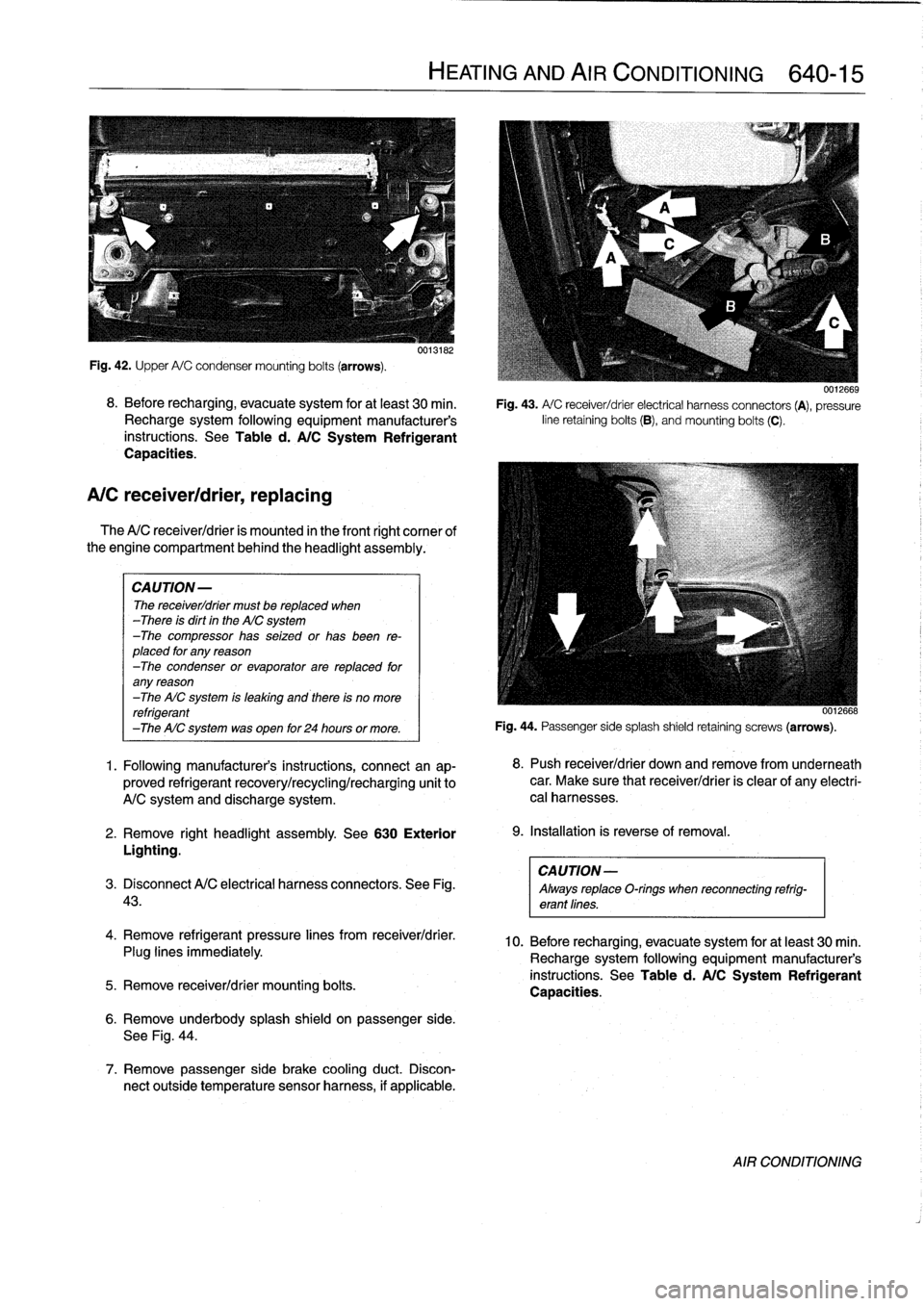
Fig
.
42
.
Upper
A/C
condensermounting
bolts
(arrows)
.
8
.
Before
recharging,
evacuate
system
for
at
least
30
min
.
Recharge
system
following
equipment
manufacturer's
instructions
.
See
Table
d
.
A/C
System
Refrigerant
Capacities
.
A/C
receiver/drier,
replacing
The
A/C
receiver/drier
is
mounted
in
the
front
right
cornee
of
the
engine
compartment
behind
the
headlight
assembly
.
CAUTION-
The
receiver/drier
must
be
replaced
when
-There
is
dirt
in
the
AIC
system
-The
compressor
has
seized
or
has
been
re-
placed
for
any
reason
-The
condenser
or
evaporator
are
replaced
for
any
reason
-The
AIC
system
is
leaking
and
there
is
no
more
refrigerant
-The
AIC
system
was
open
for
24
hours
or
more
.
1
.
Following
manufacturer's
instructions,
connectan
ap-
proved
refrigerant
recovery/recycling/recharging
unit
to
A/C
system
and
discharge
system
.
2
.
Remove
right
headlight
assembly
.
See
630
Exterior
Lighting
.
CAUTION-
3
.
Disconnect
A/C
electrical
harness
connectors
.
See
Fig
.
Always
replaceO-rings
when
reconnecting
refrig-
43
.
erant
lines
.
4
.
Remove
refrigerant
pressure
lines
from
receiver/drier
.
Plug
lines
immediately
.
5
.
Remove
receiver/drier
mounting
bolts
.
0013182
6
.
Remove
underbody
splash
shield
on
passenger
side
.
See
Fig
.
44
.
7
.
Remove
passenger
side
brake
cooling
duct
.
Discon-
nect
outside
temperature
sensor
harness,
if
applicable
.
HEATING
AND
AIR
CONDITIONING
640-15
0012669
Fig
.
43
.
A/
C
receiver/drier
electrical
harness
connectors
(A),
pressure
line
retaining
bolts
(B),
andmounting
bolts
(C)
.
0012668
Fig
.
44
.
Passenger
sidesplash
shield
retaining
screws
(arrows)
.
8
.
Push
receiver/drier
down
andremove
from
underneath
car
.
Make
sure
that
receiver/drier
is
clear
of
any
electri-
cal
harnesses
.
9
.
Installation
is
reverse
of
removal
.
10
.
Before
recharging,
evacuate
system
for
at
least
30
min
.
Recharge
system
following
equipment
manufacturer's
instructions
.
See
Table
d
.
A/C
System
Refrigerant
Capacities
.
AIR
CONDITIONING
Page 463 of 759

CAUTION
-
Always
replace
O-rings
when
reconnecting
refrig-
erant
fines
.
9
.
Before
recharging,
evacuate
system
for
at
least
30
min
.
Recharge
system
following
equipment
manufacturer's
instructions
.
See
Table
d
.
A/C
System
Refrigerant
Capacities
.
A/C
evaporator,
removing
and
installing
1
.
Followingmanufacturer's
instructions,
connectanap-proved
refrigerant
recovery/recycling/recharging
unit
to
A/C
system
and
discharge
system
.
2
.
Remove
complete
heater
boxas
described
earlier
.
3
.
Remove
expansion
valve
as
described
earlier
.
4
.
Unfasten
evaporator
sensor
electrical
harness
connec-
tor
and
puli
out
sensor
from
ieft
side
of
heater
box
.
See
Fig
.
50
.
Fig
.
49
.
Pull
out
evaporator
sensor
from
housing
in
direction
of
arrow
.
5
.
Remove
rear
heater
box
cover
.
6
.
Remove
clips
retaining
lower
evaporator
housingcover
.
Tilt
outheater
core,
then
pull
evaporator
out
of
housing
.
7
.
Installation
is
reverse
of
removal
.
CAUTION
-
Always
reptace
O-rings
when
reconnecting
refrtg-
erant
fines
.
8
.
Before
recharging,
evacuate
system
for
at
least
30
min
.
Recharge
system
following
equipment
manufacturer's
instructions
.
See
Table
d
.
A/C
System
Refrigerant
Capacities
.
HEATING
AND
AIR
CONDITIONING
640-17
8
.
Installation
is
reverse
of
removal
.
A/C
evaporator
temperature
sensor,
replacing
ou12b46
The
evaporator
temperature
sensor
is
mounted
in
the
left
(driver)
side
of
theheater
box
behind
thecenter
console
.
1
.
Remove
lower
dash
panel
and
knee
boister
on
driver
side
.
See
513
Interior
Trim
.
2
.
Remove
left
footwell
ventilation
duct
byremoving
re-
taining
rivet
in
bottom
of
duct
.
Pull
it
down
and
away
from
heater
box
.
See
Fig
.
50
.
Fig
.
50
.
Left
footwellventilatíon
duct
(arrow)
.
0o1300ba
3
.
Disconnect
sensor
electrical
connector
from
heater
box
.
Pull
sensor
straight
out
of
heater
box
.
Refer
to
Fig
.
49
.
4
.
Installation
is
reverse
of
removal
.
Table
c
.
lists
evapo-
rator
temperature
sensor
test
values
.
Tablec
.
Evaporator
Temperature
Sensor
Test
Values
Test
temp
.
Resistance
23°F
(-5°C)
11
.4
-11
.9
k
ohms
32°F
(0°C)
8
.8
-
9
.2
k
ohms
41
°F
(5°C)
6
.8
-
7
.2
k
ohms
50°F
(10°C)
5
.3-5
.6
k
ohms
59
°
F
(15°C)
4
.2
-4
.5
k
ohms
68°F
(20°C)
3
.3
-
3
.6
k
ohms
77°F
(25°C)
2
.6-2
.9
k
ohms
86°F
(30°C)
2
.1
-
2
.3
k
ohms
95°F
(35°C)
1
.7
-1
.9
k
ohms
AIR
CONDITIONING
Page 466 of 759

650-2
RADIO
"
A
320-watt
Harmon-Kardon
ten
speaker
system,
including
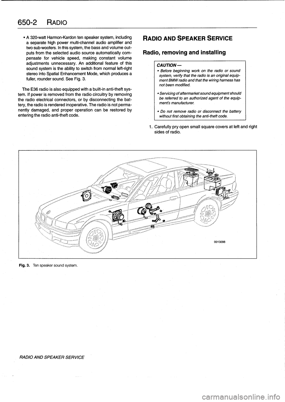
RADIO
AND
SPEAKER
SERVICE
a
separate
high
power
multi-channel
audio
amplifier
and
two
sub-woofers
.
In
this
system,
thebass
and
volume
out-
puts
from
the
selected
audiosource
automatically
com-
Radio,
removing
and
installing
pensate
for
vehicle
speed,
making
constant
volume
adjustments
unnecessary
.
An
additional
feature
ofthis
CAUTION-
sound
system
is
the
ability
to
switch
from
normal
left-right
"
Before
beginning
work
on
the
radio
or
sound
stereo
into
Spatial
Enhancement
Mode,
which
produces
a
system,
verify
that
the
radio
is
an
original
equip-
fuller,
rounder
sound
.
See
Fig
.
3
.
ment
BMW
radio
and
that
thewiring
harness
has
not
been
modified
.
TheE36
radio
is
also
equipped
with
a
built-in
anti-theft
sys-
tem
.
lf
power
is
removed
from
the
radio
circuitry
by
removing
the
radio
electrical
connectors,
or
by
disconnecting
the
bat-
tery,
the
radio
is
rendered
inoperative
.
The
radio
is
not
perma-
nently
damaged,
and
proper
operation
can
be
restored
by
entering
the
radio
anti-theft
code
.
Fig
.
3
.
Ten
speaker
sound
system
.
RADIO
AND
SPEAKER
SERVICE
"
Servicing
of
aftermarket
sound
equipment
should
be
referredto
an
authorized
agent
of
the
equip-
ment's
manufacturer
.
"
Do
not
remove
radio
or
disconnect
the
batterywithout
first
obtaining
the
anti-theft
code
.
1.
Carefully
pry
open
small
square
covers
at
left
and
right
sides
of
radio
.
Page 468 of 759

650-
4
RADIO
3
.
Remove
speakerby
removing
mountingscrews
.
See
Fig
.
8
.
Fig
.
8
.
Speaker
mounting
screws
(arrows)
.
0012580
4
.
Disconnect
harness
connector(s)
from
speaker
.
See
Fig
.
9
.
001,58
Fig
.
9
.
Disconnect
speaker
electrical
connector(s)
in
direction
shown
(arrows)
.
5
.
Installation
is
reverse
of
removal
.
Right
footwell
speaker,
removing
and
installing
1
.
Remove
glove
compartment
lower
trim
.
See
Fig
.
10
.
2
.
Rotate
speakercover
plastic
retainer
1
/a
turn
.
Remove
door
sea¡at
edge
of
speaker
cover
.
See
Fig
.
11
.
3
.
Pul¡
speaker
trim
panel
away
from
body
and
then
pul¡
panel
back
toward
rear
of
car
.
RADIO
AND
SPEAKER
SERVICE
0012582
Fig
.
10
.
Remove
lower
glove
compartment
trim
panel
retaining
screw
(black
arrow)
.
Pull
trim
in
direction
shown
(white
arrows)
.
0012583
Fig
.
11
.
Speaker
cover
retainer
(black
arrow)
.
Pulltrim
in
direction
shown
(white
arrow)
.
4
.
Remove
speaker
by
removing
mountingscrews
.
Dis-
connect
harness
connector(s)
from
speaker
.
5
.
Installation
is
reverse
of
removal
.
Page 472 of 759

720-2
SEAT
BELTS
WARNING
-
"
For
maximum
protection
from
injury,
seat
belts
should
be
replaced
as
a
set
(including
all
hard-
ware),
if
they
are
subject
to
occupant
loading
in
a
collision
.
"
Seat
belts
should
not
be
modified
or
repaired
.
The
seat
belt
anchorage
points
should
not
be
changed
or
modified
.
"
Do
notbleach
or
dye
seat
belt
webbing
.
Webbing
that
is
severely
fadedor
re-dyed
will
not
meet
the
strength
requirements
of
a
collision
and
must
be
replaced
.
"
Seat
belts
shouldbe
periodically
inspected
for
webbing
defects
suchas
cuts
or
pulled
threads
.
FRONT
SEATBELT
ASSEMBLY
Automatic
Front
Seat
Belt
Lock
Tensioners
The
procedure
for
disabling
the
mechanical
spring
tension-
er
used
on
early
cars
is
covered
below
.
On
cars
with
thepyro-
technic(explosive
device)
tensioners,
the
orange
harness
connectorshould
be
removed
from
the
tensioner
any
time
the
seat
is
removed
.
WARNING
-
Both
the
mechanical
and
the
pyrotechnictensioners
are
powerful
devíces
and
shouldbehandled
with
extreme
care
.
Mechanical
spring
tensioner,
disarming
1
.
Remove
front
seat
.
See
520
Seats
.
2
.
Disarm
tensioner-electrically
adjustableseats
:
"
Working
at
side
of
seat,
turn
activating/deactivating
screw
clockwise
until
display
changes
from
green
to
red
.
See
Fig
.
2
.
"
Before
reinstalling
seat,
turn
screw
until
display
chang-
esback
to
green
.
NOTE-
Green
is
armed
.
Red
is
disarmed
.
3
.
Disarm
tensioner-manually
adjustable
seats
:
"
Cut
wíre
tie
next
to
tab
on
bowden
cable
.
See
Fig
.
3
.
"
Turn
and
lift
tabto
disengage
cable
housing
from
seat
bracket
.
"
Disconnect
cable
end
from
seat
lever
.
"
When
reinstalling,
correctly
engage
tab
end
of
cable
into
seat
bracket
and
fasten
in
position
using
new
wíre
tie
.
FRONT
SEATBELT
ASSEMBLY
0012737
Fig
.
2
.
Electrically
adjustable
front
seat
.
Turn
screw
(A)
to
disarm
me-
chanical
tensioner
.
Display
B
tucos
from
green
to
red
.
F19
.3
.
Manuallyadjustablefrontseat
.Turnandlifttab(arrow)todis-
Page 479 of 759

1
.
Disconnect
negative
(-)
cable
from
battery
and
cover
negative
terminal
with
insulating
material
.
CA
UTION-
Prior
to
disconnectiog
the
battery,
read
the
battery
disconnection
cautions
given
at
the
front
of
this
manual
on
page
viii
.
2
.
Remove
driver
sideairbag
from
steering
wheel
.
See
Driver
side
airbag,
removing
and
installing
in
this
repair
group
.
3
.
With
wheels
facing
straight
ahead
and
steering
wheel
centered,
remove
steering
wheel
.
See320
Steering
and
Wheel
Alignment
.
4
.
Remove
contact
ring
cover
(flat
plastic
ring
containing
warning
text)
from
steering
wheel,
íf
applicable
.
5
.
Disconnect
ground
wire,
if
applicable
6
.
Lift
out
plastic
lock
from
steering
wheel,
if
applicable
.
See
Fig
.
2
.
0011903
Fig
.
2
.
Airbag
contact
ring
lock(arrow)
.
Pry
out
lock
and
remove
spríng
from
behind
lock
.
Some
airbag
steering
wheels
are
not
equipped
with
contact
ring
lock
.
WARNING
-
"
The
contact
ring
lock
holds
the
contact
ring
in
the
centered
position
.
Once
the
lock
is
removed,
the
contact
ring
is
free
to
rotate
.
Do
not
allow
the
con-
tact
ring
to
rotate
once
the
lock
is
removed
.
"
If
the
contact
ring
is
accidentally
rotated
outof
center,
turn
the
ring
either
fully
clockwise
orcoun-
terclockwise,
then
turn
in
the
opposite
direction
3
complete
revolutions
until
the
alignment
arrow
canbe
seen
through
the
lock
opening
.
AIRBAG
SYSTEM
(SRS)
721-
3
Airbagcontact
ring,
replacing
7
.
Remove
mounting
nutsor
screws
from
contact
ring
.
See
Fig
.
3
.
Disconnect
wire
lead(s)
andremove
contact
The
airbag
contact
ring
is
mounted
to
the
rear
of
the
steer-
ring
from
rear
of
steering
wheel
.
ing
wheel
and
is
made
up
of
a
wireribbon
that
cofs
and
un-
coils
as
the
steering
wheel
is
tumed
.
The
contact
ring
assures
continuous
electrical
contact
to
the
driver
side
airbag
unit
.
Fig
.
3
.
Airbag
contact
ring
mounting
fasteners(arrows)
.
8
.
Installation
is
reverse
ofremoval,noting
the
following
:
"
Coat
horn
slip
ring
(electrical
contact
ring)
with
CRC
®
copper
paste
before
installing
steering
wheel
.
"
Press
on
lower
lock
until
it
ís
fully
engaged
.
"
When
installing
contact
ringlock,
make
sure
lock
spring
engages
pins
on
lock
and
lock
cover
.
"
Special
instructions
apply
when
installing
airbag
equipped
steering
wheel
.
See320
Steering
and
Wheel
Alignment
.
Early
cars
(through
1993)
:
"
Route
wiring
lead
for
horn
through
squareopening
in
steering
wheel
.
"
When
installing
a
new
contact
ring
from
BMW,
remove
locking
screw
after
installing
the
contact
ringto
steer-
ing
wheel
.
See
Fig
.
4
.
"
Lock
contact
ring
mounting
fasteners
in
place
using
lacquer
paint
or
varnish
.
0011904
Fig
.
4
.
Airbag
contact
ring
locking
screw
(arrow),
as
installed
on
new
replacement
part
from
BMW
(early
production
cars)
.
AIRBAG
SENSORS
AND
ELECTRONICS