1994 BMW 318i Repair group 130
[x] Cancel search: Repair group 130Page 50 of 759

100-8
ENGINE-GENERAL
Symptom
1
Probable
cause
and
correctiveaction
1
.
Engine
will
not
start
or
run
.
Starter
cranks
a
.
No
fuel
reaching
engine
.
Check
forfuelin
tank
.
engine
at
normal
speed
.
Fuel
pump
notoperating
.
Repair
Group
160
b
.
No
spark
.
Check
ignition
system
.
Repair
Group
120
c
.
Incorrect
valve
timing
.
Check
timing
chain
.
Repair
Group
117
2
.
Check
Engine
warning
light
illuminated
.
a
.
DME
engine
management
system
self-diagnostic
fault
detected
.
Sea
an
authorized
BMW
dealer
or
other
qualified
shop
for
OBD
II
fault
code
diagnosis
.
See
also
On-
board
Diagnostics(OBD),
given
later
inthis
repair
group
.
3
.
White
exhaust
smoke
(steam)
.
a
.
Failed
cylinder
head
gasket
(probably
accompanied
bylowcompression
readings)
.
Replace
gasket
and
resurface
cylinder
head
if
necessary
.
Repair
Group
113
4
.
Blue-gray
exhaust
smoke
and
oily
spark
a
.
Contaminated
or
gasoline-diluted
engine
oil
.
Change
engine
oil
and
replace
oil
filter
.
plugs
.
Indicates
oii
burning
in
combustion
.
Repair
Group
020
b
.
Faulty
valve
guide
seals
or
valve
guides
.
Replace
valve
guide
oil
seals
or
overhaul
cylinder
head
.
Repair
Group
116
5
.
Pinging
or
rattling
when
under
load,
a
.
Ignition
timing
too
advanced
.
Ignition
knocksensors
faulty
(CheckEngine
light
traveling
uphill,
or
accelerating,
especially
illuminated)
.
Repair
Group
120fromlow
speeds
.
Indicates
pre-ignition
or
b
.
Fuel
octane
leve¡
toolow
.
detonation
.
c
.
Engine
running
too
hot
or
overheating
.
Check
cooling
system
.
Repair
Group
170
6
.
Light
metallic
tapping
that
varies
directly
with
engine
speed
.
Oil
pressure
warning
light
not
illuminated
.
7
.
Light
metallic
knock
that
varies
directly
with
enginespeed
.
Oil
pressure
warning
light
blinking
or
fully
illuminated
;
may
be
most
noticeable
during
hard
stops
or
cornering
.
8
.
Screeching
or
squealing
under
load
that
a
.
Loose,worn,
or
damaged
drive
belt
.
Inspect
belt(s)
.
Repair
Group
020
goesaway
when
coasting
.
9
.
Growling
or
rumbling
that
varieswith
engine
a
.
Remove
drive
belt(s)toidentifyfaulty
component
.
Check
for
play,
bearing
roughness,
rpm
.
Indicates
abad
bearing
or
bushing
in
and
loose
mountings
.
Refer
to
appropriate
repair
group
for
repair
procedures
.
an
engine-driven
accessory
.
DRIVEABILITY
TROUBLESHOOTING
On-Board
Diagnostics
(OBD)
On-Board
Diagnostics
is
incorporated
into
al¡
engine
man-
Two
generations
of
OBD
are
usedon
thecars
covered
by
agement
systems
used
on
the
cars
covered
by
this
manual
.
this
manual
:
Therefore,
checking
for
fault
codes
should
be
the
first
step
in
troubleshootinga
driveability
problem
.
For
additional
informa-
On-Board
Diagnostics
tion
on
engine
management
and
repair
see130
Fuel
Injec-
tion
.
"
1992-1995models
....
.
..
....
.
..
.......
OBD
I
"
1996-1998models
.
....
..
.
.
.
..
.
........
OBD
II
DRIVEABILITY
TROUBLESHOOTING
Tablec
.
Engine
Mechanical
Troubleshooting
b
.
Warped
or
cracked
cylinder
head
.
Resurface
or
replace
cylinder
head
.
Repair
Group
113
c
.
Cracked
cylinder
block
.
Replace
engine
or
short
block
.
c
.
Worn
piston
rings
.
Overhaul
or
replace
engine
.
d
.
Failed
cylinder
head
gasket
.
Replace
gasket
.
Repair
Group
113
d
.
Air/fuel
mixture
too
lean
(Check
Engine
light
illuminated)
.
Repair
Group
130
a
.
Valveclearances
excessive
.
Check
hydraulic
valve
adjusters
.
Repair
Group
116
b
.
Low
oil
pressure
orpossibly
defective
warning
light
circuit
.
Check
oil
pressure
andwarning
light
circuit
.
Repair
Group
119
c
.
Dirty
oil
.
Change
oil
.
Repair
Group
020
.
a
.
Low
oil
leve¡
.
Check
and
correct
oil
leve¡
.
b
.
Low
oil
pressure/worn
or
faulty
oil
pump
.
Oil
pump
pickup
restricted/clogged
.
Check
oil
pressure
.
Repair
Group
119
The
OBD
system
detects
emissions-related
engine
manage-
ment
malfunctions
and
tucos
on
the
Check
Engíne
lightin
the
in-
strument
cluster
.
TheCheck
Engine
light
will
stay
on
until
the
code(s)are
called
up
and
the
memory
is
erased
.
When
faulty
are
detected,
the
OBD
system
stores
a
Diagnostic
Trouble
Code
(DTC)
in
the
system
ECM
.
In
addition,
the
Check
Engine
warn-
ing
light
will
come
on
if
an
emissions-related
fault
is
detected
.
Page 51 of 759

NOTE-
"
On
carswith
OBD
ti,
specialized
OBD
11
scan
tool
equipment
must
be
used
to
access
the
DTCs,
either
using
the
BMW
special
tool
ora
`generic"
OBD
11
scan
tool
.
See
130
Fuel
Injection
.
"
The
08D
11
fault
memory
(including
an
iiluminated
Check
Engine
light)
can
only
be
reset
using
the
spe-
cial
scan
tool
.
Removing
the
connector
from
the
ECM
or
disconnecting
the
battery
will
not
erase
the
fault
memory
.
Table
d
.
OBD
1
Fault
(Blink)
Codes
(1992-1995
modeis
only)
Graphic
representation
of
flashing
Check
Engine
light
fault
code
:
1221
5
Seconds
.
:-
2
.5~-
--05--
Fault
code
and
meaning
1
Corrective
action
Code
1216
:
Throttle
potentiometer
Code
1218
:
Output
stage,
group#1
(DME
3
.3
.ionly)
Code
1219
:
Output
stage,
group
#2
(DME
3
.3.1
only)
Code
1221
:
Oxygen
sensor
#1
Code
1224
:
Air
temperature
sensor
(NTC)
Code
1226
:
Knock
sensor
#2
(DME
3
.3
.1
only)
130
ENGINE-GENERAL
100-
9
2
.5
seconds,
then
go
off
for
2
.5
seconds
.
At
thispoint,
the
fault
codes
will
begin
to
flash
.
See
Table
d
.
If
more
than
one
fault
has
been
detected,
eachcode
will
be
separated
by
a2
.5
second
pause
.
When
al¡
fault
codes
havebeen
displayed,
there
will
be0
.5
second
flash
and
thenthe
light
will
remain
off
.
To
read
the
codes
again,
turn
the
key
off
and
then
on
again
.
Depress
theaccelerator
pedal
to
the
floor
five
times
quickly
(within
5
seconds)
.
The
codes
will
begin
to
repeat
.
On
cars
with
OBD
I,
fault
codes
can
be
read
by
turning
the
To
erase
the
fault
code
memory,
first
make
sure
the
fault
ignition
key
on
and
fully
depressing
theaccelerator
pedal
to
code
1000
(short
blink
and
then
light
goes
out
for
long
period)
the
floor
five
times
within
five
seconds
.
TheCheck
Engine
is
present,
then
depress
the
throttle
fully
for
at
least
10
sec-
light
will
then
remain
on
for
five
seconds,
blink
off,
come
on
for
onds
.
Read
the
fault
codes
as
described
earlier
and
check
for
the
1444
code
(no
faults
stored)
.
-,--------------
Check
Engine
light
on
Check
Engine
light
off
Code
1211
:
DM
E
Control
Module
DME
control
module
may
be
faulty
.
This
code
appears
if
the
control
module
fails
the
self
test
.
Check
inputsto
control
module
.
Repair
Group
130
Code
1215
:
Mass
air
flow
sensor
Check
air
flow
or
mass
air
flow
sensor
and
wiring
to
sensor
.
Repair
Group
130
Test
throttle
potentiometer
resistance
and
wiring
.
Repair
Group
130
Test
DME
control
module
input/outputs
.
Repair
Group
130
Test
DME
control
module
input/outputs
.
Repair
Group
130
Check
sensor
output
signal
to
DME
control
module
.
Repair
Group
Code
1222
:
Oxygen
sensor
lean/rich
control
stop
Check
for
intake
air
leaks
or
reasons
forrich
míxture
.
See
Driveabil-
ity
Troubleshooting
given
earlier
in
this
repair
group
Code
1223
:
Coolant
temperaturesensor
(NTC)
1
Test
coolant
temperature
sensor
.
Repair
Group
130
Test
intake
air
temperature
sensor
.
Repair
Group
130
Code
1225
:
Knock
sensor#1
(DME
3
.3
.1
only)
1
Check
knocksensorand
sensor
wiring
.
Repair
Group
120
Check
knocksensor
and
sensor
wiring
.
Repair
Group
120
Code
1231
:
Batteryvoltage
monitor
Test
battery
voltage
and
battery
check
charging
system
and
starter
.
Repair
Group
121
Code
1234
:
Speedometer
"A"signal
(DME
3
.3
.1
only)
Check
wiring
between
instrument
cluster
and
DME
control
module
.
Electrical
Wiring
Diagrams
Code
1237
:
A/C
compressor
cutoff
(DME
3
.3
.1
only)
Test
DME
control
module
inputs/outputs
from
A/C
system
.
Repair
Group
130
Code
1242
:
A/C
compressor
signal
(DME
3
.3.1
only)
Test
DME
control
module
inputs/outputs
from
A/C
system
.
Repair
Group
130
DRIVEABILITY
TROLIBLESHOOTING
Page 52 of 759
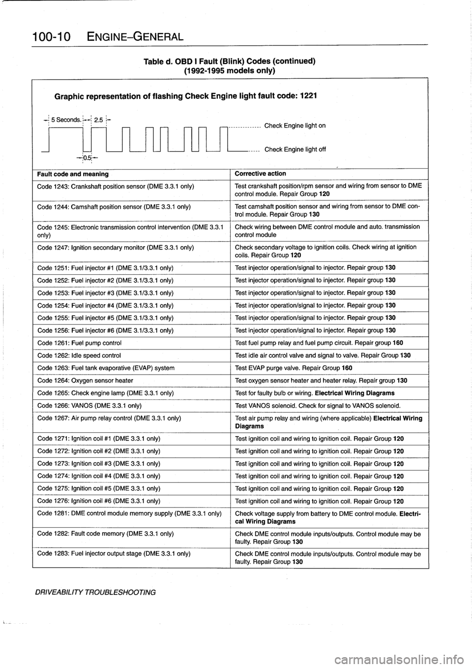
100-
1
0
ENGINE-GENERAL
Table
d
.
OBD
I
Fault
(Blink)
Codes
(continued)
(1992-1995
modeis
only)
Graphic
representation
of
flashing
Check
Engine
light
fault
code
:
1221
-
;
5
Seconds
.
;--~
2
.5
r
----------------
Check
Engine
light
on
Fault
code
and
meaning
Corrective
action
Check
Engine
light
off
Code
1243
:
Crankshaft
position
sensor
(DME
3
.3
.1
only)
Test
crankshaft
position/rpm
sensor
and
wiring
from
sensor
lo
DME
control
module
.
Repair
Group
120
Code
1244
:
Camshaft
position
sensor
(DME
3
.3
.1
only)
Test
camshaft
position
sensor
and
wiring
fromsensor
to
DME
con-
trol
module
.
Repair
Group
130
Code
1245
:
Electronic
transmission
control
intervention
(DME
3
.3
.1
Check
wiring
between
DME
control
module
and
auto
.
transmission
only)
control
module
Code
1247
:
Ignition
secondary
monitor
(DME
3
.3
.1
only)
Check
secondary
voltage
lo
ignition
coils
.
Check
wiringat
ignition
coils
.
Repair
Group
120
Code
1251
:
Fuel
injector
#1
(DME
3
.113
.3
.1
only)
1
Test
injector
operation/signal
lo
injector
.
Repair
group130
Code
1252
:
Fuel
injector
#2
(DME
3
.113
.3
.1
only)
Test
injector
operation/signal
lo
injector
.
Repair
group130
Code
1253
:
Fuel
injector
#3
(DME
3
.1/3
.3
.1
only)
Test
injector
operation/signal
to
injector
.
Repair
group130
Code
1254
:
Fuel
injector
#4
(DME
3
.1/3
.3
.1
only)
Test
injector
operation/signal
to
injector
.
Repair
group
130
Code
1255
:
Fuel
injector
#5
(DME
3
.1/3
.3
.1
only)
Test
injector
operation/signal
to
injector
.
Repair
group130
Code
1256
:
Fuel
injector
#6
(DME
3
.1/3
.3
.1
only)
Test
injector
operation/signal
lo
injector
.
Repair
group130
Code
1261
:
Fuel
pump
control
Test
fuel
pump
relay
and
fuel
pump
circuit
.
Repairgroup
160
Code
1262
:
Idle
speed
control
Test
idleair
controlvalve
and
signalto
valve
.
Repair
Group
130
Code
1263
:
Fuel
tank
evaporative
(EVAP)
system
Test
EVAP
purge
valve
.
Repair
Group
160
Code
1264
:
Oxygen
sensor
heater
1
Test
oxygen
sensorheater
and
heater
relay
.
Repair
group
130
Code
1265
:
Check
engine
lamp
(DME
3
.3.1
only)
1
Test
for
faulty
bulb
or
wiring
.
Electrical
Wiring
Diagrams
Code
1266
:
VANOS
(DME
3
.3
.1
only)
1
Test
VANOS
solenoid
.
Check
for
signal
to
VANOS
solenoid
.
Code
1267
:
Air
pump
relay
control
(DME
3
.3
.1
only)
Test
air
pump
relay
and
wiring
(where
applicable)
Electrical
Wiring
Diagrams
Code
1271
:
Ignition
coil
#1
(DME
3
.3.1
only)
Test
ignitioncoil
and
wiring
toignitioncoil
.
Repair
Group
120
Code
1272
:
Ignition
coil
#2
(DME
3
.3.1
only)
Test
ignitioncoil
and
wiring
loignitioncoil
.
Repair
Group
120
Code
1273
:
Ignition
coil
#3
(DME
3
.3.1
only)
Test
ignitioncoil
and
wiring
loignitioncoil
.
Repair
Group
120
Code
1274
:
Ignítion
coil
#4
(DME
3
.3.1
only)
Test
ignitioncoil
and
wiring
toignitioncoil
.
Repair
Group
120
Code
1275
:
Ignitioncoil
#5
(DME
3
.3.1
only)
Test
ignition
coil
and
wiring
loignitioncoil
.
Repair
Group
120
Code
1276
:
Ignition
coil
#6
(DME
3
.3.1
only)
Test
ignitioncoil
and
wiring
loignitioncoil
.
Repair
Group
120
Code
1281
:
DME
control
module
memory
supply
(DME
3
.3
.1
only)
Check
voltage
supply
from
battery
lo
DME
control
module
.
Electri-
Code
1282
:
Fault
code
memory
(DME
3
.3.1
only)
Check
DME
control
module
inputs/outputs
.
Control
module
may
be
faulty
.
Repair
Group
130
Code
1283
:
Fuel
injector
output
stage
(DME
3
.3
.1
only)
Check
DME
control
module
inputs/outputs
.
Control
module
may
be
faulty
.
Repair
Group
130
DRIVEABILITY
TROUBLESHOOTING
cal
Wiring
Diagrams
Page 53 of 759

Graphic
representation
of
flashing
Check
Engine
light
fault
code
:
1221
-
;
5
Seconds
.
~-
2
.5;-
Fault
code
and
meaning
Corrective
action
Code
1286
:
Knock
control
test
pulse
(DME
3
.3
.1
only)
Check
DME
control
module
inputs/outputs
.
Control
module
may
be
faulty
Repair
Group
130
Code
1000
(light
remains
off)
:
End
of
fault
code
output-all
fault
codes
have
been
displayed
.
No
~
corrective
action
necessary
.
Repeat
test
if
necessary
Code
1444
:
No
more
faults
.
No
corrective
action
necessary
.
This
code
must
be
present
lo
erase
fault
memory
Basic
Requirements
Preventive
Maintenance
The
following
list
contains
basic
checks
that
should
be
made
when
experiencing
driveability
problems
.
1
.
Check
intake
(induction)
system
for
leaks
.
Check
for
cracked,
loose,
or
disconnected
hoses
and
duct
work
.
Check
that
all
hose
clamps
are
tight
.
NOTE-
An
air
leak
allows
unmeasured
airto
enter
the
engine,
offen
resulting
in
an
in
overly
lean
fuel
mixture
and
causing
driveability
problems
which
will
cause
the
Check
Engine
light
to
come
on
.
Table
d
.
OBD
I
Fault
(Blink)
Codes
(continued)
(1992-1995
models
only)
7
-
1
--------------
Check
Engine
light
on
ENGINE-GENERAL
100-
1
1
Check
Engine
light
off
The
condition
of
the
fuel,
ignition
and
emission
controlsys-
tem
components
has
a
directeffect
onengineperformance
and
driveability
.
BMW
specifies
maintenance
of
certain
parts
at
regular
intervals
lo
keep
the
engine
in
proper
tune
.
Extend-
ing
maintenance
intervals
beyond
the
time
or
mileagerecom-
mended
bythe
manufacturer
can
adversely
affect
the
way
the
engine
runs
.
When
troubleshooting
driveability
problems,
a
good
starting
point
is
to
perform
a
major
engine
service,par-
ticularly
if
one
is
overdue
.
For
maintenance
schedules,
major
engine
service
and
other
driveability-related
maintenance
procedures,
see020
Maintenance
Program
.
Basic
Engine
Settings
2
.
Check
that
the
battery
isin
good
condition
.
Check
that
the
cables
are
tight
and
free
of
corrosion
at
both
ends
.
Idle
speed,
idle
mixture
(%CO),
and
ignition
timing
are
not
Check
that
all
related
ground
points
are
firmly
connect-
adjustable
.
The
adaptive
engine
management
system
is
de-
ed
and
in
good
condition
.
Check
al¡
harness
connectors
signed
lo
automatically
compensate
for
changes
in
engine
op-
for
damage
and
corrosion
.
erating
conditions,
although
the
adaptive
range
is
limited
.
Once
these
limits
are
exceeded,
driveability
problems
usually
3
.
Check
for
prwer
and
ground
at
the
Engine
Control
become
noticeable
.
Module
(ECM)
.
Check
the
main
grounds
for
the
ECM
.
See130
Fuel
Injection
.
NOTE-
If
the
DME
adaptive
limits
are
exceeded,
the
Check
En-
4
.
Check
the
fuses
.
Check
for
sufficient
fuel
in
the
tank
.
If
gine
light
will
come
on,
indicating
an
emission
related
the
engine
ranout
of
fuel,
it
will
take
a
little
time
to
re-
fault
.
See
130
Fuel
Injection,
store
fuel
pressure
.
See
160
Fuel
Tank
and
Fuel
Pump
.
Oxygen
Sensors
5
.
Check
for
spark
at
the
spark
plugs
.
If
the
tachometer
needle
bounces
while
the
engine
is
crankedby
the
A
high
oxygen
level
in
the
engine
exhaust
indicates
a
lean
starter
then
the
ignition
system
is
probably
working
cor-
air-fuel
mixture
and
a
low
oxygen
level
indicates
a
rich
mix
rectly
.
See
120
Ignition
System
.
ture
.
The
oxygen
sensor,
shown
in
Fig
.
10,
measures
the
oxy-
gen
content
in
the
exhaust
gasand
generates
a
variable
6
.
Check
for
any
faults
through
the
On-Board
Diagnostics
voltage
signal
.
Using
that
feedback
signal
asan
input,
the
system
.
See
On-Board
Diagnostics
(OBD)
.
DME
control
module
fine
tunes
the
air-fuel
mixture
.
DRIVEABILITY
TROUBLESHOOTING
Page 56 of 759

100-
1
4
ENGINE-GENERAL
0013131
Fig
.
13
.
Main
chassis
ground
(arrow)
inleft
front
of
engine
compart-
ment
.
Fuel
Supply
For
the
engine
tostart
and
run
properly,
the
injection
sys-
tem
must
deliver
fuel
in
precise
proportion
to
the
amount
of
air
entering
the
engine
.
Todo
this,
the
injection
system
requires
an
unrestricted
supply
of
fuel
from
the
fuel
pump
.
If
the
fuel
pump
is
not
working,
the
engine
will
notrun
.
If
the
fuel
filter
or
a
fuel
line
is
restricted,
the
engine
may
run
poorly
.
If
the
restriction
is
severe
enough
the
engine
will
not
start
.
lf
fuel
delivery
problemsare
suspected,
perform
the
tests
de-
scribed
in
160
Fuel
Tank
and
Fuel
Pump
.
The
fuel
pressure
created
by
the
fuel
pump
is
controlled
by
a
pressure
regulator
thatreturns
excess
fuelto
the
tank
.
Any
change
in
fuel
pressure
will
cause
a
change
in
the
base
air-fuel
mixture
delivered
to
the
engine
.
If
the
fuel
pressure
is
too
low,
the
base
air-fuel
mixture
will
be
lean
.
lf
the
fuel
pressure
is
too
high,
the
base
mixture
will
be
rich
.
Fuel
pressure
tests
aredescribed
in
160
Fuel
Tank
and
Fuel
Pump
and130
Fuel
Injection
.
NOTE-
Fuel
pressure
tests
require
a
pressure
gauge
.
If
thistoolís
not
avaílable,
the
tests
can
be
performed
byan
authorized
BMW
dealer
or
other
qualified
shop
.
DRIVEABILITY
TROUBLESHOOTING
Properly
operating
fuel
injectors
play
amajor
role
in
fuel
de-
livery
.
The
DMEECM
switches
the
injectors
on
and
off
at
the
negative
(-)
or
ground
side
of
the
connectors
.
Posítíve
(+)
bat-
tery
voltage
is
always
present
at
the
connectors
when
theen-
gine
is
running
.
An
injector
that
fails
or
loses
power
will
not
open,
creating
a
lean
air-fuel
mixture
and
causing
the
engine
to
run
poorly
when
coldor
stumble
on
acceleration
.
An
injector
that
shorts
to
ground
will
remain
open
constantly
when
the
en-
gine
is
running,
creating
a
richair-fuel
mixture
that
can
dilute
engine
oil,
foul
the
spark
plugs,
cause
a
rough
idle,
and
damage
the
catalytic
converter
.
Table
e
lists
additional
symptoms
of
common
engine
drive-
ability
problems,
their
probable
causes,
and
the
suggested
corrective
actions
.
The
entries
in
boldtype
in
the
corrective
action
column
indicate
the
repair
groups
where
applicable
test
and
repair
procedures
can
befound
.
NOTE-
Most
of
the
symptoms
fisted
in
Table
e
will
also
cause
the
Check
Engine
light
to
come
on
.
If
the
light
is
on,
check
for
any
stored
faults
as
the
first
step
ín
trouble-
shooting
driveability
complaints
.
Page 57 of 759

al
Icld
Table
e
.
Engine
Driveability
Troubleshooting
c
l
1
I
f
I
I
Oxygen
sensor
faulty
Test
oxygen
sensor
.
ENGINE-GENERAL
100-
1
5
SYMPTOMS
a
.
Engine
fafs
tostart
b
.
Engine
startsbut
stops
immediately
c
.
Erratic
engine
idle
d
.
Poor
engine
responseon
acceleration
e
.
Erratic
engine
operation
in
al¡
speed
ranges
f
.
Excessive
fuel
consumption
g
.
Poor
enginepower,
fails
to
rev
up
h
.
CO
content
toolow
i.
CO
content
too
high
CAUSES
CORRECTIVE
ACTION
a
Fuel
pump
faulty
Test
fuel
pump
.
Repair
Group
160
a
e
Ignition
system
faulty
Test
ignition
system
.
Repair
Group
120
a
Main
relay
or
fuel
pump
relay
faulty
Test
main
relay
.
Repair
Group
130
a
Crankshaft/rpm
position
sensor
faulty
Test
crankshaft/rpm
sensor
.
120
b
c
h
i
ldle
speed
control
valve
faulty
Test
idle
speed
control
valve
.
c
d
e
Throttle
position
sensor
faulty
or
idle
signal
to
Test
throttle
position
sensor
.
DME
control
module
missing
.
c
d
h
i
Mass
air
flow
sensor
faulty
Test
mass
air
flow
sensor
Repair
Group
130
a
b
c
d
e
h
Large
air
intake
system
leak
Check
for
major
intake
air
leaks
downstream
of
mass
air
flow
sensor
.
a
c
d
e
g
h
Fuel
pressure
too
low
Test
fuel
pressure
.
Repair
Group
130
?
I
F
ue
l
pr
essu
r
e
t
oo
high
T
est
f
u
el
pressure
.
Repair
Group
130
d
e
g
h
Fuel
pump
delivery
volume
too
low
Test
fuel
pump
delivery
volume
.
Repair
Group
160
a
c
e
f
h
q
C
oo
l
a
nt
t
e
mp
e
r
a
t
u
r
e
se
n
so
r
f
au
lty
--]
T
est
coo
l
a
n
t
temp
erature
sensor
.
c
e
~
f
i
~
Fuel
injectors
leaking
Check
fuel
injectors
and
replace
leaking
injectors
.
~
Repair
Group
130
Throttle
plate
binding
or
incorrectly
adjusted
Check
throttle
plate
and
adjust
if
necessary
.
a
c
Electrical
connections
loose,
broken,
or
cor-
Visually
inspect
connectors
and
correct
any
roded
faults
.
Repair
Group
600
Ground
connections
loose,
broken,
or
corroded
Visually
inspect
ground
connections
and
correct
any
faults
.
Repair
Group
600
c
e
~
f
CO
content
too
high
Test
air
flowor
mass
air
flow
sensor
.
Repair
~
Group
130
a
b
c
d
e
CO
content
too
low
Test
mass
air
flow
sensor
.
gb
c
d
e
f
g
h
i
Inputsignals
to
ECM
missing,
ECM
in
limp
Make
electrical
tests
at
DMEECM
relay
.
Repair
home
mode
Group
130
a
~
b
~
c
~
d
e]
f
g
h
i
ECM
faulty
Test
DMEECM
inputs
.
If
all
inputs
are
correct,
replace
ECM
.
DRIVEABILITY
TROUBLESHOOTING
Page 106 of 759

117-
1
0
CAMSHAFT
TIMING
CHAIN
21
.
On
1993
and
lates
engines
:
Remove
access
plugs
from
24
.
On
1993
and
later
engines
:
VANOS
control
unit
in
front
of
exhaust
camshaft
"
Remove
VANOS
control
unit
as
described
laterinthis
sprocket
.
Remove
4
bolts
from
exhaust
camshaft
repair
group
.
sprocket
(useTono
El0
socket)
.
See
Fig
.
26
.
"
Remove
intake
camshaft
sprocket
mounting
nuts
.
"
Remove
intake
and
exhaust
sprockets
together
with
secondary
chain
.
Note
location
of
thrust
washers
and
spring
plate
(where
applicable)
on
intake
sprocket
.
Fig
.
26
.
Exhaust
camshaftmounting
bolts
(arrows)
.
CAMSHAFT
TIMING
CHAINS,
6-CYLINDER
0013056
22
.
Depress
secondary
timing
chain
tensiones
and
lock
down
by
inserting
stiff
wire
into
the
openings
in
rear
of
tensioner
.
See
Fig
.
27
.
Fig
.
27
.
Secondary
timing
chaintensioner
being
locked
down
on
M50
engine
.
Press
tensioner
downand
insert
locking
wire
through
holes(arrows)
.
Tensioner
on
M52/S52
US
engines
vary
slight-
23
.
Remove
secondary
chain
tensioner
and
lift
out
primary
chain
guide
.
NOTE-
Hold
the
camshaft
stationary
(at
hex
on
camshaft)
when
loosening
ortightening
sprocket
mounting
boits
.
CAUTION-
The
crankshaft
must
not
be
allowed
to
rotate
once
the
timing
chain
is
removed
.
The
pistons
can
con-
tact
the
valves
.
25
.
On
1992
engines
:
"
Remove
from
intake
and
exhaust
sprocket
mounting
bolts
.
"
Remove
sprockets
together
with
secondary
chain
.
26
.
Remove
bolts
holding
lower
timing
chain
cover
to
cylin-
der
head
(use
Torx
E8
socket)
.
See
Fig
.
28
.
MR111:
R
Fig
.
28
.
Cylinderhead-to-timingchain
covermounting
bolts
(arrows)
.
27
.
Using
a
drift,
drive
two
locatiog
dowels
in
left
and
right
sides
of
lower
timing
chaincover
toward
rear
of
car
.
Re-
move
covermounting
boits
and
carefully
lift
cover
off
.
See
Fig
.
29
.
CA
UTION-
Use
care
when
removing
the
cover
from
the
cylin-
der
head
gasket
.
If
the
cover
is
stuck,
useasharp
knife
to
separate
it
from
the
head
gasket
.
Page 125 of 759
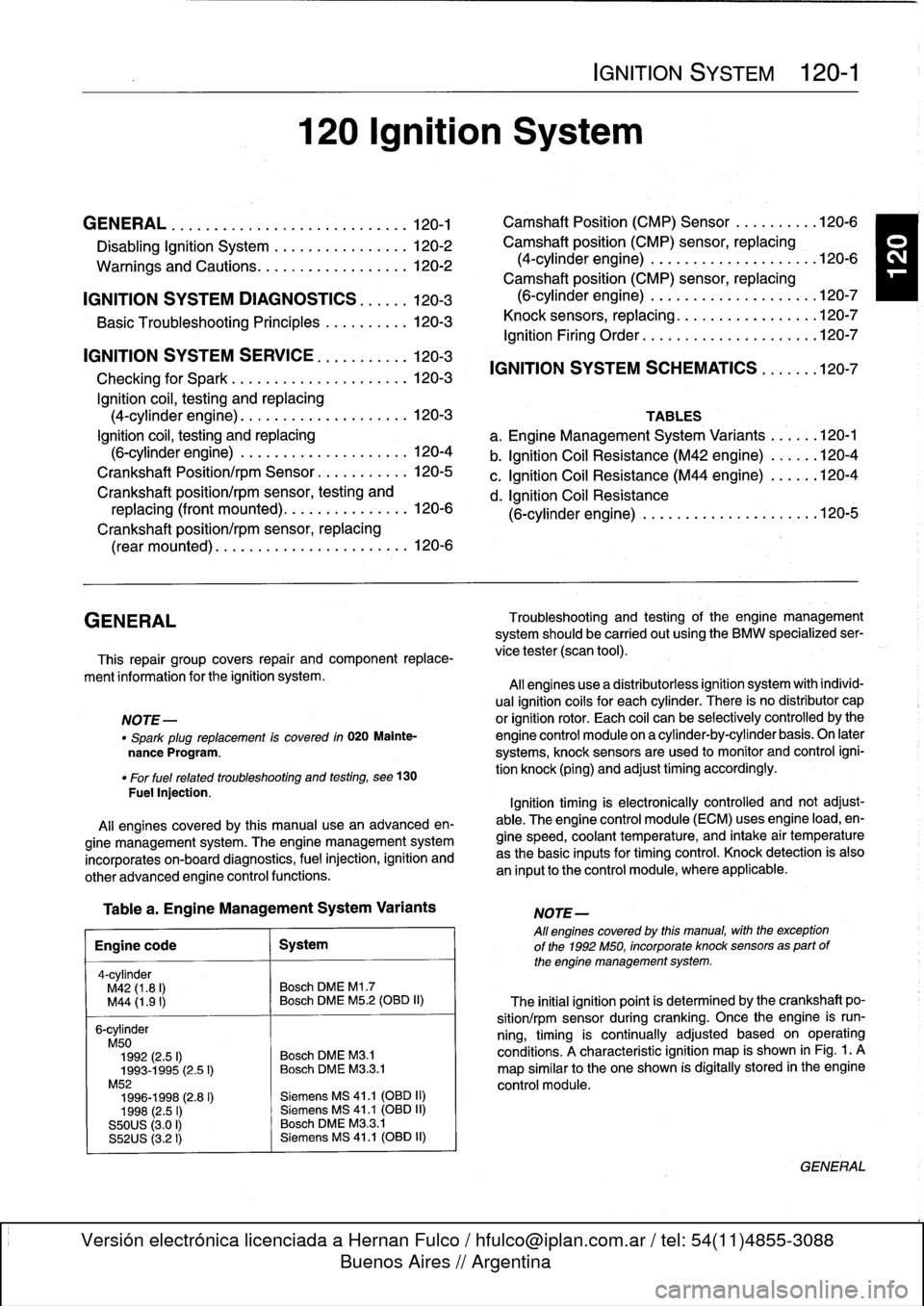
GENERAL
.
........
.
...........
.
.
.
.
.
.
.
120-1
Camshaft
Position
(CMP)
Sensor
....
.
.
.
...
120-6
Disabling
Ignition
System
.
.
.
.
.....
.
.
.
.
.
.
.
120-2
Camshaft
position
(CMP)
sensor,
replacing
Warnings
and
Cautions
.
.
.
.
.
.
.....
.
.
.
.
.
.
.
120-2
(4-cylinder
engine)
..
.
.
.
.
.
.
.
.
.
.
.
.
.
.
.
...
120-6
Camshaft
position
(CMP)
sensor,
replacing
IGNITION
SYSTEM
DIAGNOSTICS
.
.
.
.
.
.
120-3
(6-cylinder
engine)
..
.
.
.
.
.
.
.
.
.
.
.
.
.
.
.
.
.
.
120-7
Basic
Troubleshooting
Principles
...
.
.
.
.
.
.
.
120-3
Knock
sensors,
replacing
.
.
...
.
.
.
.
.
.
.
.
.
.
.
.
120-7
Ignition
Firing
Order
.....
.
...
.
.
.
.....
.
.
.
.120-7
IGNITION
SYSTEM
SERVICE
.
.........
.
120-3
Checking
for
Spark
..
.
.
.
.
.
.
.
.
.
.......
.
.
.
120-3
Ignition
coil,
testing
and
replacing
(4-cylinder
engine)
.
.
.
.
.
.
.
.
.
.
.........
.
120-3
Ignition
coil,
testing
and
replacing
(6-cylinder
engine)
.........
.
..........
120-4
Crankshaft
Positionlrpm
Sensor
.......
.
...
120-5
Crankshaft
position/rpm
sensor,
testing
and
replacing
(front
mounted)
.........
.
.
.
.
.
.
120-6
Crankshaft
position/rpm
sensor,replacing
(rear
mounted)
.....
.
.....
.
.....
.
.
.
.
.
.
120-6
GENERAL
Troubleshooting
and
testing
of
the
engine
management
system
should
be
carried
out
using
the
BMW
specialized
ser
This
repair
group
covers
repair
andcomponent
replace-
vice
tester
(scan
tool)
.
ment
information
for
the
ignition
system
.
All
engines
use
a
distributorless
ignition
system
with
indívid-
ual
ignitioncoils
for
each
cylinder
.
There
is
no
distributor
cap
NOTE-
or
ignition
rotor
.
Each
coil
can
be
selectively
controlled
by
the
"
Spark
plug
replacement
is
covered
in
020
Mainte-
engine
control
module
on
a
cylinder-by-cylinder
basis
.
On
later
nance
Program
.
systems,
knock
sensors
are
used
to
monitor
and
control
igni-
"
For
fuel
related
troubleshooting
and
testing,
see
130
tion
knock
(ping)
and
adjusttiming
accordingly
.
Fuel
lnjection
.
Ignition
timing
is
electronically
controlled
and
not
adjust-
All
engines
covered
by
this
manual
use
an
advanced
en-
able
.
The
engine
control
module
(ECM)
usesengine
load,
en-
gine
management
system
.
The
engine
management
system
gine
speed,
coolant
temperature,
and
intake
air
temperature
incorporates
on-board
diagnostics,
fuel
injection,
ignition
and
as
the
basic
inputs
for
timing
control
.
Knock
detection
is
also
other
advanced
engine
control
functions
.
an
input
to
the
control
module,
where
applicable
.
Table
a
.
Engine
Management
System
Variants
Engine
code
1
System
4-cylinder
M42
(1.8
I)
Bosch
DME
Ml
.7
M44
(1
.9
I)
Bosch
DME
M5
.2
(OBD
II)
6-cylinder
M50
1992
(2.5
I)
Bosch
DME
M8
.1
1993-1995
(2
.5
I)
Bosch
DME
M33
.1
M52
1996-1998
(2.8
I)
Siemens
MS
41
.1
(OBD
II)
1998
(2
.5
I)
Siemens
MS
41
.1
(013D
11)
S50US
(3.0
I)
Bosch
DME
M3
.3.1
S52US
(3.2
I)
Siemens
MS
41
.1
(OBD
II)
120
Ignition
System
IGNITION
SYSTEM
120-1
IGNITION
SYSTEM
SCHEMATICS
...
.
.
.
.120-7
TABLES
a
.
Engine
Management
System
Variants
......
120-1
b
.
Ignition
Coil
Resistance
(M42
engine)
......
120-4
c
.
Ignition
Coil
Resistance
(M44
engine)
......
120-4
d
.
Ignition
Coil
Resistance
(6-cylinder
engine)
..
.
.
.
.
.
.
.
.
.
.
.
.....
.
..
120-5
NOTE-
All
engines
coveredby
this
manual,
with
theexception
of
the
1992
M50,
incorporate
knocksensors
as
part
of
the
engine
management
system
.
The
initial
ignition
point
is
determined
by
the
crankshaft
po-
sition/rpm
sensor
during
cranking
.
Once
the
engine
is
run-
ning,
timing
is
continually
adjusted
based
on
operating
conditions
.
A
characteristic
ignition
map
is
shown
in
Fig
.
1
.
A
map
similar
to
the
one
shown
is
digitally
stored
in
the
engine
control
module
.
GENERAL