Page 1071 of 1413
lllustrated Index
CAUTION:
. All SRS electrical wiring harnossos are cover€d withyellow insulation.
. B€fors disconnacting any part of the SRS wire har-ness, connsct the 3hort connsctor(s).. Replace the entirs affscted SRS harness assembly itit has an open circuit or damaged wiring.
NOTE; The original radio has a coded theft protection
circuit. Be sure to get the customer's code number
before- disconnecting the battery.- removing the No.32 (7.5 A) fuse from the under-
hood fuse/relay box.- removing the radio.
After service, reconnect Dower to the radio and turn it
on. When the word "CODE" is displayed, enter the cus-
tomer's 5-digit code to restore radio operation.
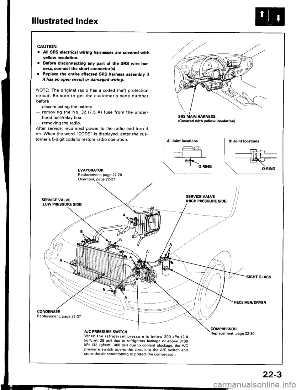
SRS MAIN HARNESSlcover€d with yellow insulationl
EVAPORATORReplacement, page 22-26Ovethaul. Oase 22.27
SERVICE VALVE(LOW PRESSURE SIDEI
SERVICE VALVEIHIGH PRESSURE SIDE)
RECEIVER/DRYER
CONDENSERReplacement, page 22,37
A/C PRESSURE SWITCHCOMPRESSORReplacement, page 22-30When the refrigerant pressure is below 200 kpa (2.0kqflcm,,28 psi) due to refrigerant leakage or above 3]OOkPa (32 kgf/cm,, 460 psi) due to coolant btockage, the A,/Cpressure switch opens the circuit to the A"/C switch andstops the air conditionang to protect the compressor.
22-3
Page 1109 of 1413
Troubleshooting
Tips and Precautions
Before Troubloshooting
a Check applicable fuses in the appropriate fuse/relay
DOX.
a Check the battery for damage, state of charge, and
clean and tight connections.a Check the alternator belt tension.
CAUTION:
a Do not quick-charg€ a battery unless the batteryground cabla has be€n disconnoctsd. oth€rwisoyou will damage the alternator diodss.a Do not att6mpt to crank the engine with the bat-tery ground cable loosely connectsd or you will se-vorsly damag€ tho widng.
a The original radio has a codod thatt plotection ci.-cuit. Be sul€ to got tho customor's code numbet
before- disconnecting th€ battery.- lomoving tho No. 32 (7.5 Al tuso f.om the
under-hood tuse/lelay box.- removing tho radio.
Aflor s€lvic€. reconn€ct powet to tho radio and
turn it on. Whon the word "CODE" is displayed,
€nt€l the customer'E s-digit codo to .astore ladio
operation.
Handling Connectors
a Make sure the connectors are clean and have no loose
wire terminals.
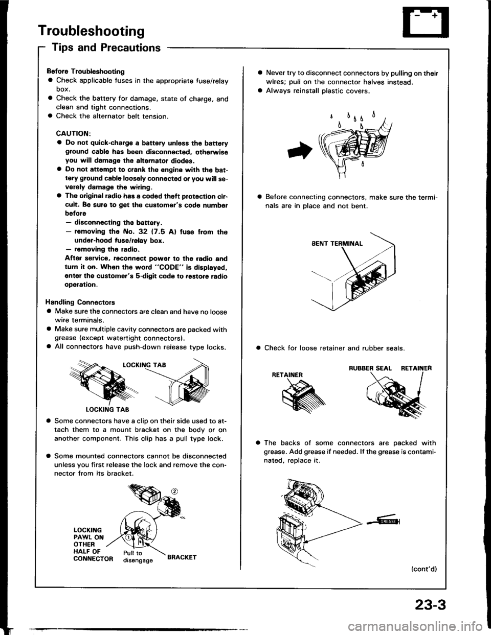
a Make sure multiple cavity connectots are packed withgrease (except watertight connectors).a All connectors have push-down release type locks.
LOCKII{G TAA
LOCKING TAB
a Some connectors have a clio on their side used to at-
tach them to a mount bracket on the body or on
another component. This clip has a pull type lock.
a Some mounted connectors cannot be disconnected
unless you first release the lock and remove the con-
nector from its bracket.
LOCKINGPAWL ONOTHERHALF OFPull toorsengageCONNECTORBRACKET
23-3
a Never try to disconnect connectors by pulling on thei.
wires; pull on the connector halves instead.
a Always reinstall plastic covers.
Belore connecting connectors, make sure the lermi-
nals are in Dlace and not bent.
a Check tor loose retainer and rubber seals.
RETAINER
a The backs of some connectors are oacked with
grease. Add grease if needed. It the grease is contami-
nated, reDlace it.
(cont'd)
Page 1138 of 1413
Connector ldentification and Wire Harness Routing
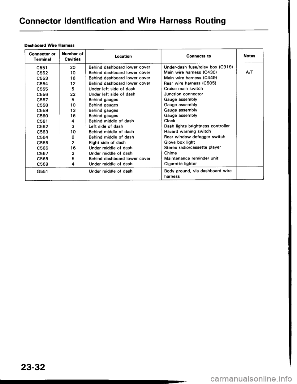
Dashboard wile Ha.n6ss
Connector ot
T€rminal
Number of
Caviti6sLocationConnects toNotes
c553
c554
L55b
c556
c557
c558
c560
LCO I
c563
c564
c565
c566
c567
c568a 6ACl
20
10
to
12
5
22
10
13
16
10
6
to
2
Behind dashboard lower cover
Behind dashboard lower cover
Behind dashboard lower cover
Behind dashboard lower cover
Under lett side oJ dash
Under left side of dash
Behind gauges
Behind gauges
Behind gauges
Behind gauges
Behind middle of dash
Left side of dash
Behind middle of dash
Behind middle of dash
Right side of dash
Under middle of dash
Under middle of dash
Behind dashboard lower cover
Under middle of dash
Under-dash fuse/relay box (C919)
Main wire harness (C43Ol
Main wire harness (C4491
Rear wire harness {C505)
Cruise main switch
Junction connector
Gauge assembly
Gauge assembly
Gauge assembly
Gauge assembly
Clock
Dash lights brightness controller
Hazard warning switch
Rear window defogger switch
Glov€ box light
Stereo radio/cassette PlaYer
Chime
Maintenance reminde. unit
Cigarette lighter
Afi
Under middle of dashBody ground, via dashboard wire
harness
23-32
Page 1155 of 1413
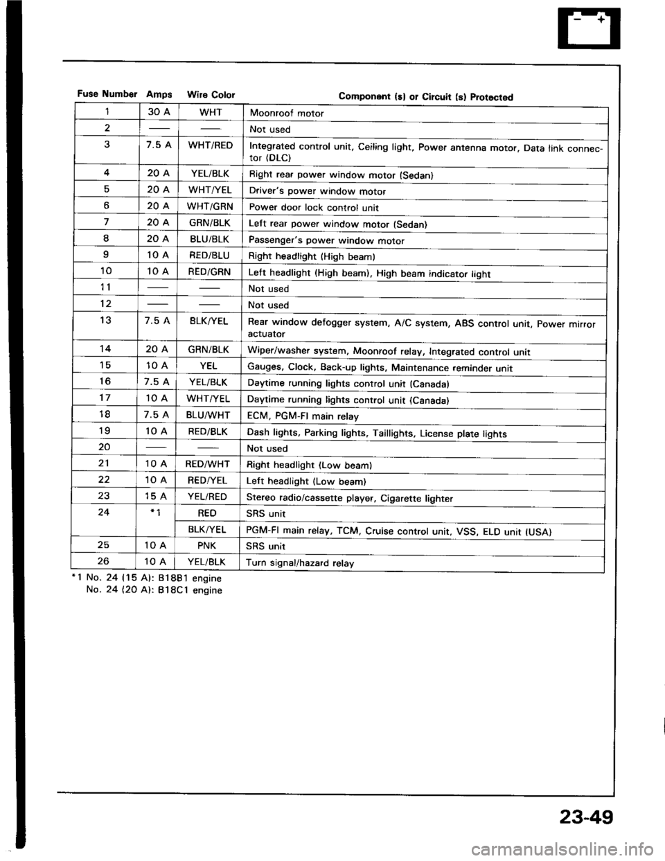
Fuse Numb€r AmDs Wire CololGomponent ls) or Circuit (s) Prot8cted
130AWHTMoonroof motor
2Not used
37.5 AWHT/REDIntegrated control unit, Ceiling light, Power antenna motor. Data link connec-tor (DLC)
420AYEL/BLKRight rea. power window motor (Sedan)
520AWHT/YELDriver's power window motor
o20AWHT/GRNPower door lock control unit
720AGRNiBLKLelt rear power window motor (Sedan)
I20ABLU/BLKPassenger's power window motor
I10 ARED/BLURight headlight {High beaml
1010 ARED/GRNLeft headlight (High beam). High beam indicato. tight
11Not used
12Not used
137.5 ABLK/YELRear window defogger system, A/C system, ABS control unit, power mrrroractuator
1420AGRN/BLKWiper/washer system, Moonroof relay, Integrated control unii'1510 AYELGauges, Clock, Back-up lights, Maintenance reminder unit
to7.5 AYEL/BLKDaytime running lights control unit (Canadal
1710 AWHT/YELDaytime running lights control unit (Csnada)
7.5 ABLU^tvHTECM, PGM-FI main relay'to10 ARED/BLKDash lights, Parking lights, Taillights, License plate tights
20Not used
2110 ARED/WHTRight headlight (Low beam)
10 ARED/YELLeft headlight (Low beam)
2315 AYEL/REDStereo radio/cassette player, Cigarette lighter
24REOSRS unit
BLK/YELPGM-FI main relay, TCM, Cruise controt unit, VSS, ELO unit IUSA)
2510 APNKSRS unit
2610 AYEL/BLKTurn signal/hazard relay'1 No.
No.
24 115 Al:
24 t2O At:.
81881 engine
B18Cl engine
23-49
Page 1158 of 1413
Fuses
Under-hood Fuse/Relay Box
ALTERI{ATOR
fTo .ngino wlto hsrno$ {Tlolll
Not usod
r: l\lot u3.d
umborAmpsColor
nF n nn46 45 /t4 35 3l
UU U UU
n32
U
n
33
U
r:rg
U
n
42
U
n43
U
[To rldidor hn r.l.Yl
Componon! (sl 01 Clrcuit 13) Protoqtod
3115 AYEL/WHTPGM-Fl main relay
327.5 AWHT/BLUECM, TCM. Clock, Stereo radio/cassette plsyer, Maintenance reminder unit
a2204BLK/REDRadiator Jan motor
34Not used
35204WHTCondenser fan motor, A/C compressor clutch
50AWHT/REDNo. I {3O A), No. 3 (7.5 A). No. 4l2O Al, No 5 (2O A), No. 7 (2O A),
No. I (20 A) fuses
3740ABLU/lVHTBlower motor
3830ABLK/GRNRear window defogger, Noise condenser
?q50AWHT/BLKlgnition switch {BAT}
4050AWHTCombination light switch, No. 17 (1O Al fuse
41100 APower distribution
4220AWHT/GRNHorn system, Brake system, Key interlock solenoid (Aff)
4310 AWHT/GRNTurn signal/hazard.elay
44Not used
45Not used
46Not used
23-52
Page 1163 of 1413
IGNITION SWTCH ISTIlFrom p.!€ 23 - 561
f7
I.---F-------lI-lSTARTFPi Bffi,!'HT 6u?'ili,iY i| -' r r l clurcr It-11iPt ;rui8rr H inl-rhicicxswrcr 1,,,,,,Itill-+{ .'.i o-F BIK/RED --.5 BLX/!\,HT - st.der sotenoid il-l I r
BLK/REO
fr
r---
uxrivn Sr$!gfr*,r.,
L€-eumoBLKMHT - Starlsr solenoki
-------J
UNDER -DASH FUSEiRELAY BOX
No.l817.5A)ELUMHT --?- PGM _ Ft msin rctay- ECM
lnt€gretod control unit
St6r6o radio/c$r€tt6 playot
Cig€rone lightor
Option connoctor: C927
Pow6r minor *tuetols
noar wandow dologgor switchindicrtor light
R6dietor fan robyElowor motor rclayfuC compr$sor clutch rsl6yA/C lhomGtstCond6ns& tan ml6yMod6 control motorRocicubtion control motorH6at€r control panolRear window deloggor relayABS pomp motor tolayABS insp€ction connoctorABS contrcl unit
Option connoctor:C925
Daytime running lightscontrolunit
(From pag623-56 )
No.23ll5AlYEURED --E
lG2lFrom p.!623- 56 ){Fus€/relay box sockotl
+ l,lo,16 {7.5A1
23-57
Page 1172 of 1413
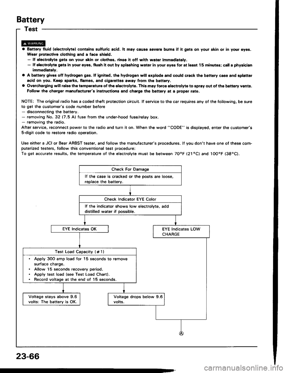
Battery
a Battory tluid (6lectrolyt€l contains sulturic acid. lt may cauaa aevere burns iI it gots on your skin or in youl oyos.
Woar protoctivo clothing and I fac€ shield,- ll aloctrolyt6 gots on youl skin or clothos, rimo it off with wator immediately,- lf eloclrolyto g6ts in your oyos, tlush it out by splashing wat6r in youl eyes for at least 15 minutes; call a physiclan
immediately,
a A battery gives off hydrogon gas, lf ignit6d. tha hydrogsn will orploda and could crack tho baflory cas6 and splattor
acid on you. Koep spa*s. flames, and cigarottos away from the baftery.
a Overcharging will raiso ths tempelature ot th€ electrolyte. This may force electrolyte to splay out of the battery venta.
Follow lhe chargor manutacturer's instluctions and chargo tho battory at a prop61 rate.
NOTE: The original radio has a coded theft protection circuit. lt service to the car requires any of the lollowing, be sure
to get the customer's code number before- disconnecting the battery.- removing No. 32 (7.5 Al fuse from the under-hood fuse/relay box- removing the radio,
After service, reconnect power to the radio and turn it on. When the word "CODE" is displayed, enter the customer's
s-digir code to restore radio operation,
Use either a JCI or Bear ARBST tester, and follow the manufacturer's procedures. It you don'r have one of these com-puterized testers, follow this conventional test procedure:
To get accurate results, the temperature ot the electrolyte must be between TOoF l21ool and IOOoF {38oCl.
lf the case is cracked or the posts are loose,
replace the battery.
lf the indicator shows low electrolvte, add
distilled water it oossible.
Test Load Cspacity (# 1)
. Apply 3OO amp losd fo. 15 seconds to remove
surJace charge.. Allow 15 seconds recovery period.. Apply test load (see Test Load Chartl.. Record voltage at the end of 15 seconds.
Voltage stays above 9.6
volts: The batterv is OK.
23-66
Page 1177 of 1413
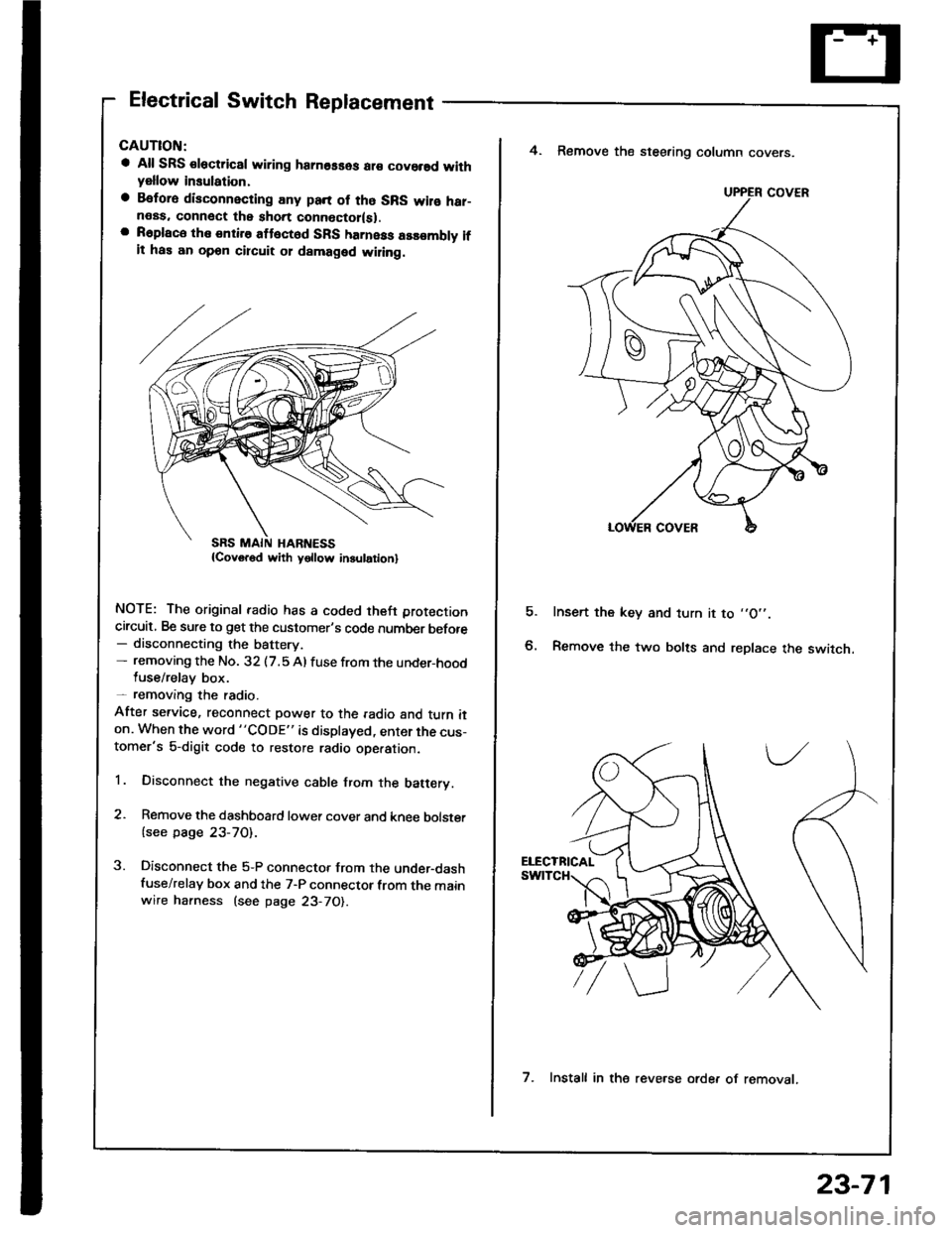
Electrical Switch Replacement
a All SRS €lectric8l wiring hamosses ar€ covorsd withyellow insulation,
a Befora disconnecting any pan of tho SRS wilo har-neas. connect the short connoctor(sl.a R6place the entire attect6d SFS harness assombly ifit has an opon circuit 01 damaged wiling.
NOTE: The original radio has a coded theft protection
circuit, Be sure to get the customer's code number before- disconnecting the battery.- removing the No. 32 (7.5 Al fuse from the under-hoodluse/relay box.- removang the radio.
After service, reconnect power to the radio and turn iton. When the word "CODE" is displayed, enter the cus-tomer's 5-digit code to restore radio ope.ation.
1. Disconnect the negative cable from the batery.
2. Remove the dashboard lower cover and knee bolster
{see page 23-70).
3. Disconnect the 5-P connector from the under-dashfuse/relay box and the 7-P connector from the mainwire harness (see page 23-70).
E
4. Remove the steering column covers.
Insert the key and turn it to ,,O',.
Remove the two bolts and replace the switch.
UPPER COVER
7. Install in the reve.se orde. of removat.
23-71