Page 268 of 1413
System Description
The idle speed ot lhe engine is controlled by the ldle Air Control {lAC) Valve.
The valve changes the amount ot air bypassing into the intake manifold in response to electric current controlled by the
ECM. When the IAC Valve is activated, the valve opens to maintain the proper idle speed.
#l' ----rTo FGM-FIMAINRELAY
VARIOUSSENSORS
IAC VALVE
FASTIDLETHERMOVALVE
INTAKE MAI{IFOLD
(cont'd)
BLK
r
11-79
Page 269 of 1413
ldle Control System
System Description (cont'd)
1 . Atter the engine slarts. the IAC valve opens for a censin time, The amount ot air is increased to raise the idle soeedabout 15O-3OO rom.
2. When the coolant temperature is low, the IAC valve is opened to obtain the proper fast idle speed. The amount ofbypassed air is thus controlled in relation to the engine coolant temperature.
IDI-E SPEEDlrpm)
176
80
ENGINECOOLANT TEMPERATURE
t"Fl(oct
11-80
Page 271 of 1413

ldle Control System
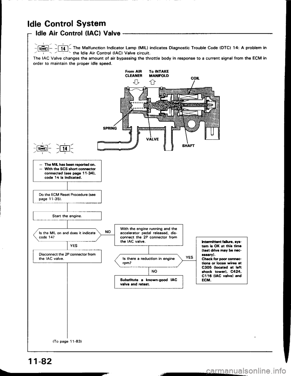
ldle Air Control (lACl Valve
lt6l- -l lf l- The Maltunction Indicator Lamp (MlL) indicates Diagnostic Trouble Code {DTC} 14: A problem in
' '- the ldle Air Control llAC) Valve circuit.
The IAC Valve changes the amount of air bypasEing the throttle body in respons€ to a current signal from the ECM in
order to maintain the proper idle speed.
ffi: r;611/ | /--T-\
- The MIL h.3 been report don,- With tho SCS shon connoctolconnoctod (soo pago 'l 'l -341,
cod6 14 is indicatod.
Do the ECM Reset Procedure (seepage 11-35).
With the engine running snd theaccelerator pedal releas€d, dis-conn€ct th€ 2P connector frorttho IAC valvo.
ls the MIL on and does it indicatecode 14?
htarmitlaot frlu]., aya-t.m i. OK !t thir tlft.
ll.rl drlv. mly ba nac-aaaaryl.Chack tor Doo. conn€c-tlonr oi loora wirca atC3O5 (loc.t.d .t |.ftlhock tow.tl, C424,Cl tB (lAC v.lvol .ndECM.
Disconnect the 2P connector fromthe IAC valve.
Sub.iituto . known{ood IACvdva lnd iotolt.
{To page 11-83}
11-82
Page 283 of 1413

ldle Control System
Fast ldle Thermo Valve
DEscliptlon
To prevent erratic running when the engine is warming
up, it is n€cessary to raise the idle speed. The fast idle
thermo valve is controlled by a thermowax plunger, When
the engine is cold. the engine coolant su.rounding the
thermowax contracts the plunger, allowing additional air
to be bypassed into the intake manifold so that the en-
gine idlss taster. When the engine reaches operating tem-
peratur€, the valve closss, reducing the amount of air
bypassing into the manifold.
FAST IDLE THERMOVALVE
AIN EYPASS VALVE
Inspaction
NOTE: The tast idle thermo valve is factory adiustsd;
it should not be disassombl€d.
1. Remove the intake air duct from the throttlg body.
2. Stan the engine.
3. Put your finger over ths lower port in throttle body
and make sure that there is 8ir flow with tho engine
cold (engine coolant temperatute below 86oF,
300c).
a lf not,
retest.
leplace the fast idle thermo valvs and
4.
o-Rr{GsReplace
llo kgf.m, 7 lbt.trl
Start the engine. Hold the sngine at 3.0OO rpm with
no load (A/T in I or @ position, M/T in neutral]
until the radiator fan comes on, then let it idl6.
Check thst valve is completely closed. lt not, air suc-
tion can be telt at the lower Don in the throttle body,
a It any suction is felt, the valve is leaking Check
engine coolant level and for air in tho engine
coolant system (see section 1O). ll OK, rsplace
the fast idle thermo valve and rechock.
11-94
Page 339 of 1413

InspectionReplacement
Flywheel, Flywheel Bearing
Inspect the ring gear teeth for wear and damage.
Inspect the clutch disc mating surface on the
flywheel fo. wear, cracks, and burning.
Measure the flywheel runout using a dial indicator
through at least two full tu.ns. Push against the
Ilywheel each time you turn it to take up the crank-
shaft thrust washe. clearance.
NOTE; The runout can be measu.ed with engine in-
stalled.
Standard (ttlervl: O.O5 mm (O.002 inl Max.
Service Limit: 0.15 mm 10.006 inl
RING GEABFLYWHEEL
DIAL II{DICATOR
It the runout is more than the service limit, leplace
the flvwheel.
Turn the inner race of the flywheel bearing with your
finger. The bearing should turn smoothly and quiet-
ly, Check that the bearing outer race fits tightly in
the flvwheel.
FLYWHEELBEARING
It the race does not turn smoothly, quietly, or fit
tight in the flywheel, replace the flywheel bearing.
Install the special tool.
Remov€ the flywhe€l mounting bolts in a criascross
pattern in several steps 8s shown, then remove the
tlywheel.
MOUI{TII{G BOLTS
3. Remov€ the flywheel bsaring from th€ tlywheel.
(cont'd)
FLYWHEEL
12-9
Page 347 of 1413
Removo tho clutch pip€ bracket and th€ slave cylin-
oer.
NOTE: Do not operate the clutch pedal once th€
slavg cvlinder has been r€moved.
R€move the three uppor transmission mounting
bolts 8nd lower staner motor mounting bolt.
STARTEBMOTOBMOUNNNGBOLT
MOUNNNGBOLTS
10. Remove the engine splash shield.
11. Disconnect the heated oxygen sensor (HO2S) con-
nector, lhsn rsmove the exhaust pipe A, and the
three way catalytic converter (B18Cl Engine).
HO2Sco NEctoRSELF.LOCK IIUTRopl.ce.
EXHAUSTPIPE A
THBEE WAYCATALYTICCONVEEIER1818C1 engin6)
SELF.LOCK NUTReplace.
13-5
Page 349 of 1413
19. Remove the clutch cover.
MOUNT/BRACKET
TRANSMISSION MOUNT
21.Place a transmission iack under the transmission
and a jack stand under the engine.
Remove the transmission mount.
23. Remove the rear mount bracket bolts and the trans-
mission mounting bolts.
24. Pull the transmission away from the engine until it
clears the mainshaft, then lower it on the transmis-
sion iack.
BRACKET
13-7
Page 384 of 1413
Transmission
Reassembly (cont'd)
11. Install the change holder assembly.
6x1.0mm15 N.m (1.5 kgf.m,11 tbf.ftl
CHANGE HOLDERASSEMBLY
Install the shift piece
the shift piece shaft.
and the interlock, then install12.
13-42
13. Measure the distance @ after mounting the shiftpiece shaft. lf it's incorrect, check the installation.
Distance O: 11.9 - 12.3 mm 10.47 - 0.48 in)
14.lnstall the washer (B18C1 engine), the reversegear. and the reverse idler gear shaft.
idlo.
REVERSE IDLER GEAR