1993 VOLKSWAGEN CORRADO low oil pressure
[x] Cancel search: low oil pressurePage 492 of 920

ELECTRICAL COMPONENT LOCATOR
Article Text (p. 34)
1993 Volkswagen Corrado
For Volkswagen Technical Site: http://vw.belcom.ru
Copyright © 1998 Mitchell Repair Information Company, LLC
Wednesday, March 22, 2000 09:09PM
Back-Up Light Switch Mounted near gear selector
shaft on transmission.
Brake Fluid Level Switch In cap on brake fluid
reservoir.
Brake/Stoplight Switch On bracket, above brake pedal.
Cooling Fan Thermoswitch On lower left side of
radiator.
Clutch Switch On bracket, above clutch
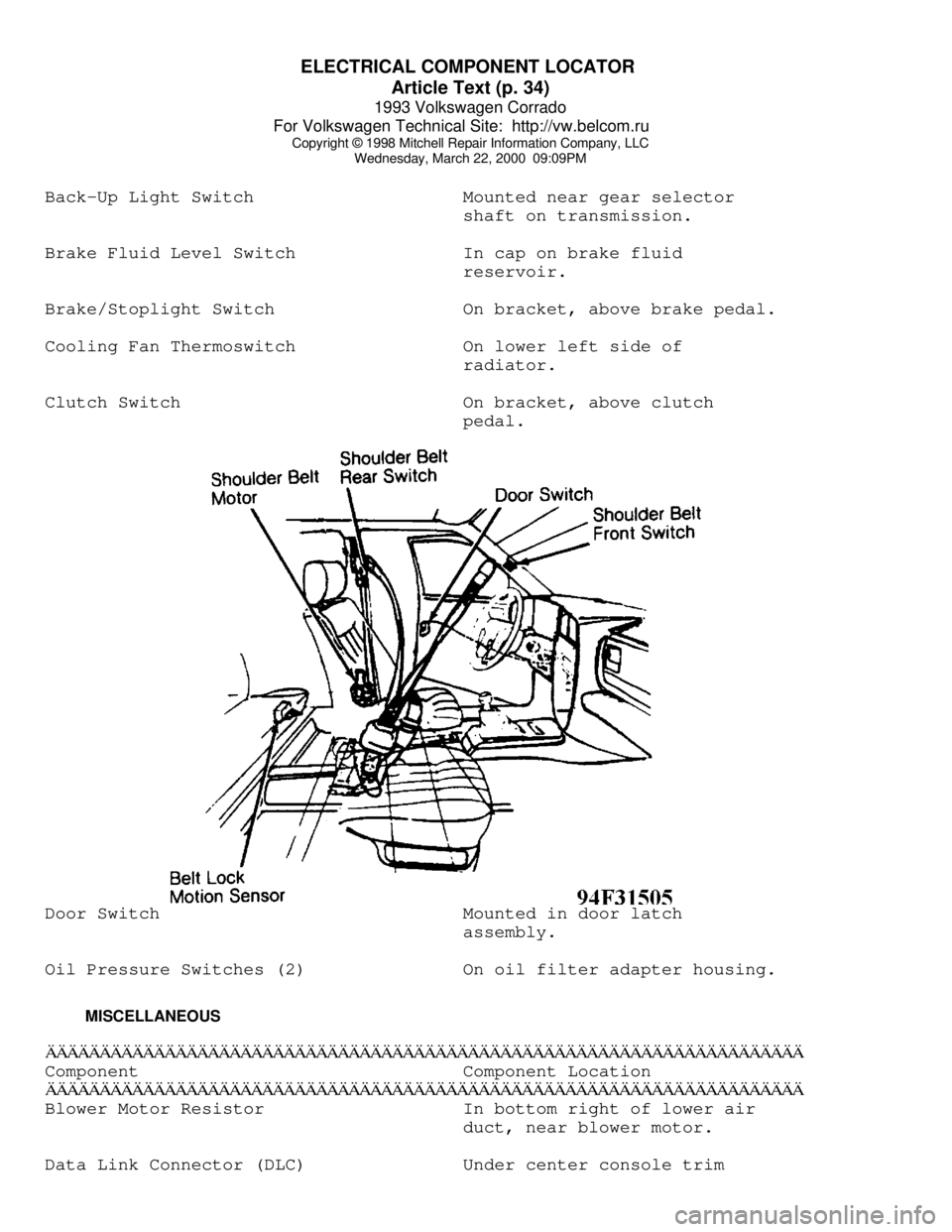
pedal.Door Switch Mounted in door latch
assembly.
Oil Pressure Switches (2) On oil filter adapter housing.
MISCELLANEOUSÄÄÄÄÄÄÄÄÄÄÄÄÄÄÄÄÄÄÄÄÄÄÄÄÄÄÄÄÄÄÄÄÄÄÄÄÄÄÄÄÄÄÄÄÄÄÄÄÄÄÄÄÄÄÄÄÄÄÄÄÄÄÄÄÄÄÄÄÄÄComponent Component Location
ÄÄÄÄÄÄÄÄÄÄÄÄÄÄÄÄÄÄÄÄÄÄÄÄÄÄÄÄÄÄÄÄÄÄÄÄÄÄÄÄÄÄÄÄÄÄÄÄÄÄÄÄÄÄÄÄÄÄÄÄÄÄÄÄÄÄÄÄÄÄBlower Motor Resistor In bottom right of lower air
duct, near blower motor.
Data Link Connector (DLC) Under center console trim
Page 532 of 920

ENGINE OVERHAUL PROCEDURES - GENERAL INFORMATION
Article Text (p. 3)
1993 Volkswagen Corrado
For Volkswagen Technical Site: http://vw.belcom.ru
Copyright © 1998 Mitchell Repair Information Company, LLC
Wednesday, March 22, 2000 09:09PM
* PLEASE READ THIS FIRST *
NOTE: Always refer to appropriate engine overhaul article in the
ENGINES section for complete overhaul procedures and
specifications for the vehicle being repaired.
GENERAL
All components of an engine do not have the same cleaning
requirements. Physical methods include bead blasting and manual
removal. Chemical methods include solvent blast, solvent tank, hot
tank, cold tank and steam cleaning of components.
BEAD BLASTING
Manual removal of deposits may be required prior to bead
blasting, followed by some other cleaning method. Carbon, paint and
rust may be removed using bead blasting method. Components must be
free of oil and grease prior to bead blasting. Beads will stick to
grease or oil soaked areas causing area not to be cleaned.
Use air pressure to remove all trapped residual beads from
components after cleaning. After cleaning internal engine parts made
of aluminum, wash thoroughly with hot soapy water. Component must be
thoroughly cleaned as glass beads will enter engine oil resulting in
bearing damage.
CHEMICAL CLEANING
Solvent tank is used for cleaning oily residue from
components. Solvent blasting sprays solvent through a siphon gun using
compressed air.
The hot tank, using heated caustic solvents, is used for
cleaning ferrous materials only. DO NOT clean aluminum parts such as
cylinder heads, bearings or other soft metals using the hot tank.
After cleaning, flush parts with hot water.
A non-ferrous part will be ruined and caustic solution will
be diluted if placed in the hot tank. Always use eye protection and
gloves when using the hot tank.
Use of a cold tank is for cleaning of aluminum cylinder
heads, carburetors and other soft metals. A less caustic and unheated
solution is used. Parts may be lift in the tank for several hours
without damage. After cleaning, flush parts with hot water.
Steam cleaning, with boiling hot water sprayed at high
pressure, is recommended as the final cleaning process when using
either hot or cold tank cleaning.
COMPONENT CLEANING
* PLEASE READ THIS FIRST *
NOTE: Always refer to appropriate engine overhaul article in the
ENGINES section for complete overhaul procedures and
Page 541 of 920

ENGINE OVERHAUL PROCEDURES - GENERAL INFORMATION
Article Text (p. 12)
1993 Volkswagen Corrado
For Volkswagen Technical Site: http://vw.belcom.ru
Copyright © 1998 Mitchell Repair Information Company, LLC
Wednesday, March 22, 2000 09:09PM
Valve Seat Replacement
Replacement of valve seat inserts is done by cutting out
the old insert and machining an oversize insert bore. Replacement
oversize insert is usually chilled and the cylinder head is sometimes
warmed. Valve seat is pressed into the head. This operation requires
specialized machine shop equipment.
Valve Seat Concentricity
Using dial gauge, install gauge pilot in valve guide.
Position gauge arm on the valve seat. Adjust dial indicator to zero.
Rotate arm 360 degrees and note reading. Runout should not exceed
specification.
To check valve-to-valve seat concentricity, coat valve face
lightly with Prussian Blue dye. Install valve and rotate it on valve
seat. If pattern is even and entire seat is coated at valve contact
point, valve is concentric with the seat.
REASSEMBLY
Valve Stem Installed Height
Valve stem installed height must be checked when new valves
are installed or when valves or valve seats have been ground. Install
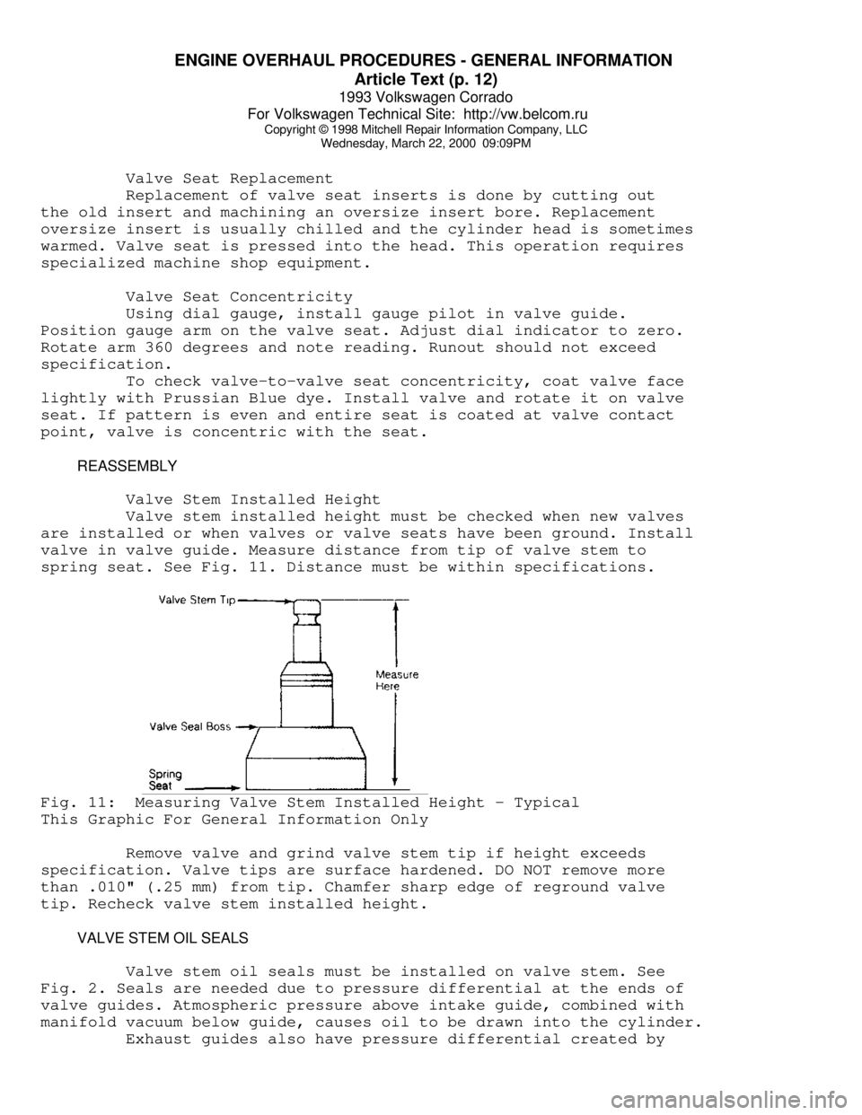
valve in valve guide. Measure distance from tip of valve stem to
spring seat. See Fig. 11. Distance must be within specifications.Fig. 11: Measuring Valve Stem Installed Height - Typical
This Graphic For General Information Only
Remove valve and grind valve stem tip if height exceeds
specification. Valve tips are surface hardened. DO NOT remove more
than .010" (.25 mm) from tip. Chamfer sharp edge of reground valve
tip. Recheck valve stem installed height.
VALVE STEM OIL SEALS
Valve stem oil seals must be installed on valve stem. See
Fig. 2. Seals are needed due to pressure differential at the ends of
valve guides. Atmospheric pressure above intake guide, combined with
manifold vacuum below guide, causes oil to be drawn into the cylinder.
Exhaust guides also have pressure differential created by
Page 542 of 920

ENGINE OVERHAUL PROCEDURES - GENERAL INFORMATION
Article Text (p. 13)
1993 Volkswagen Corrado
For Volkswagen Technical Site: http://vw.belcom.ru
Copyright © 1998 Mitchell Repair Information Company, LLC
Wednesday, March 22, 2000 09:09PM
exhaust gas flowing past the guide, creating a low pressure area. This
low pressure area draws oil into the exhaust system.
Replacement (On Vehicle)
Mark rocker arm or overhead cam components for location.
Remove rocker arm components or overhead cam components. Components
must be installed in original location. Remove spark plugs. Valve stem
oil seals may be replaced by holding valves against seats using air
pressure.
Air pressure must be installed in cylinder using an adapter
for spark plug hole. An adapter can be constructed by welding air hose
connection to spark plug body with porcelain removed.
Install adapter in spark plug hole. Apply a minimum of 140
psi (9.8 kg/cmý) to adapter. Air pressure should hold valve closed. If
air pressure does not hold valve closed, check for damaged or bent
valve. Cylinder head must be removed for service.
Using valve spring compressor, compress valve springs. Remove
valve locks. Carefully release spring compressor. Remove retainer or
rotator and valve spring. Remove valve stem oil seal.
If oversized valves have been installed, oversized oil seals
must be used. Coat valve stem with engine oil. Install protective
sleeve over end of valve stem. Install new oil seal over valve stem
and seat on valve guide. Remove protective sleeve. Install spring
seat, valve spring and retainer or rotator. Compress spring and
install valve locks. Remove spring compressor. Ensure valve locks
are fully seated.
Install rocker arms or overhead cam components. Tighten all
bolts to specification. Adjust valves if required. Remove adapter.
Install spark plugs, valve cover and gasket.
VALVE SPRING INSTALLED HEIGHT
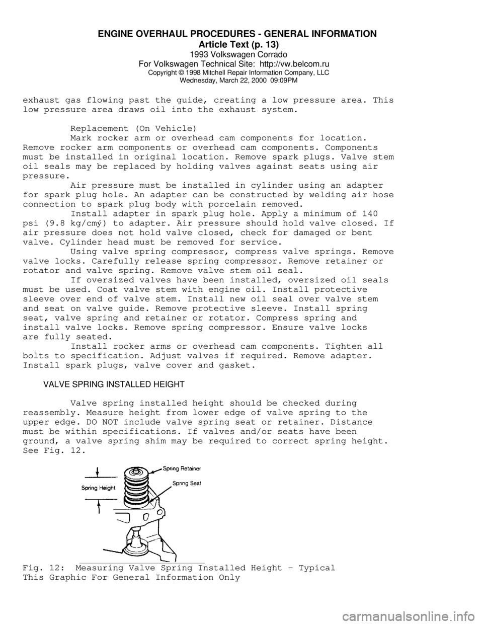
Valve spring installed height should be checked during
reassembly. Measure height from lower edge of valve spring to the
upper edge. DO NOT include valve spring seat or retainer. Distance
must be within specifications. If valves and/or seats have been
ground, a valve spring shim may be required to correct spring height.
See Fig. 12.Fig. 12: Measuring Valve Spring Installed Height - Typical
This Graphic For General Information Only
Page 565 of 920

ENGINE OVERHAUL PROCEDURES - GENERAL INFORMATION
Article Text (p. 36)
1993 Volkswagen Corrado
For Volkswagen Technical Site: http://vw.belcom.ru
Copyright © 1998 Mitchell Repair Information Company, LLC
Wednesday, March 22, 2000 09:10PM
to ensure correct amount of oil has filled crankcase. Check oil level
while pre-oiling.
If pressure oiler is not available, disconnect ignition
system. Remove oil pressure sending unit and replace with oil pressure
test gauge. Using starter motor, rotate engine starter until gauge
shows normal oil pressure for several seconds. DO NOT crank engine
for more than 30 seconds to avoid starter motor damage.
Ensure oil pressure has reached the most distant point from
the oil pump. Reinstall oil pressure sending unit. Reconnect ignition
system.
INITIAL START-UP
Start the engine and operate engine at low speed while
checking for coolant, fuel and oil leaks. Stop engine. Recheck coolant
and oil level. Adjust if necessary.
CAMSHAFT
Break-in procedure is required when a new or reground
camshaft has been installed. Operate and maintain engine speed between
1500-2500 RPM for approximately 30 minutes. Procedure may vary due to
manufacturers recommendations.
PISTON RINGS
Piston rings require a break-in procedure to ensure seating
of rings to cylinder walls. Serious damage may occur to rings if
correct procedures are not followed.
Extremely high piston ring temperatures are produced obtained
during break-in process. If rings are exposed to excessively high RPM
or high cylinder pressures, ring damage can occur. Follow piston ring
manufacturer's recommended break-in procedure.
FINAL ADJUSTMENTS
Check or adjust ignition timing and dwell (if applicable).
Adjust valves (if necessary). Adjust carburetion or injection idle
speed and mixture. Retighten cylinder heads (if required). If
cylinder head or block is aluminum, retighten bolts when engine is
cold. Follow the engine manufacturer's recommended break-in procedure
and maintenance schedule for new engines.
NOTE: Some manufacturer's require that head bolts be retightened
after specified amount of operation. This must be done to
prevent head gasket failure.
END OF ARTICLE
Page 569 of 920

F - BASIC TESTING
Article Text (p. 4)
1993 Volkswagen Corrado
For Volkswagen Technical Site: http://vw.belcom.ru
Copyright © 1998 Mitchell Repair Information Company, LLC
Wednesday, March 22, 2000 09:10PM
kg/cmý). Turn engine off. After 10 minutes, residual pressure should
be 29 psi (2 kg/cm
ý). If system pressure is too high, replace fuel
pressure regulator.
3) If residual pressure is too low, operate engine until
system pressure builds up, then pinch off Blue fuel return line. If
pressure holds, replace the fuel regulator. If fuel pressure is low,
check for leaks at fuel lines, fuel injectors and fuel pump check
valve
TRANSFER PUMP CHECK
Transfer Pump Fuel Volume Check
1) Turn ignition off. To check transfer pump (in tank),
remove rear seat. Remove fuel sending unit access cover. Disconnect
ignition coil secondary wire and jumper to ground.
2) With transmission in Neutral, crank engine for 3-4
seconds. While starter is turning and for a few seconds afterwards, an
audible sound should be heard at the pump. If sound is not heard, go
to next step. If sound is heard, go to step 5).
3) Remove fuel pump relay from relay panel. On Corrado and
Passat, activate fuel pumps using Remote Control (VAG 1348/3A). On all
other models, activate fuel pumps using Remote Control (US 4480/3). On
all models, if pump does not operate, remove transfer pump wire
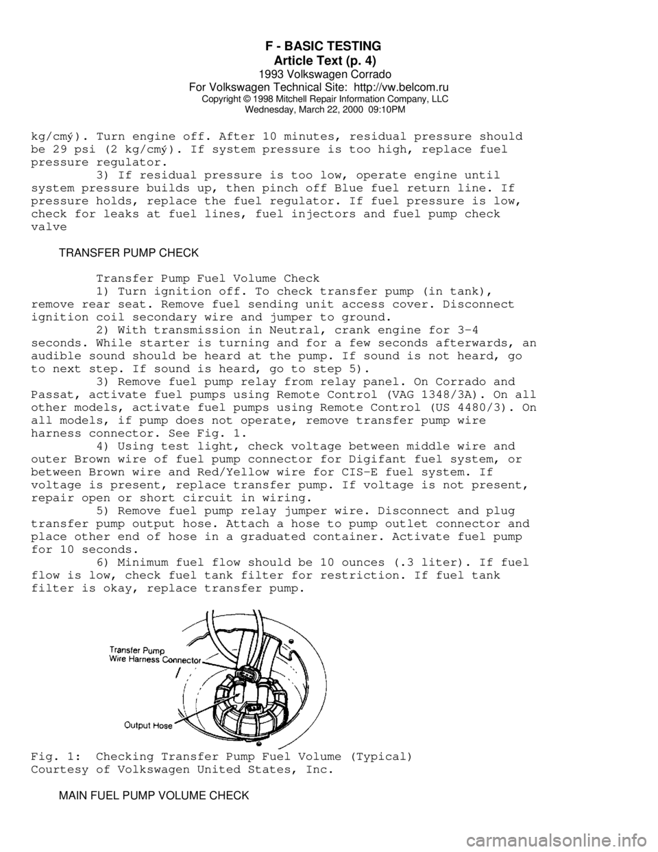
harness connector. See Fig. 1.
4) Using test light, check voltage between middle wire and
outer Brown wire of fuel pump connector for Digifant fuel system, or
between Brown wire and Red/Yellow wire for CIS-E fuel system. If
voltage is present, replace transfer pump. If voltage is not present,
repair open or short circuit in wiring.
5) Remove fuel pump relay jumper wire. Disconnect and plug
transfer pump output hose. Attach a hose to pump outlet connector and
place other end of hose in a graduated container. Activate fuel pump
for 10 seconds.
6) Minimum fuel flow should be 10 ounces (.3 liter). If fuel
flow is low, check fuel tank filter for restriction. If fuel tank
filter is okay, replace transfer pump.Fig. 1: Checking Transfer Pump Fuel Volume (Typical)
Courtesy of Volkswagen United States, Inc.
MAIN FUEL PUMP VOLUME CHECK
Page 571 of 920

F - BASIC TESTING
Article Text (p. 6)
1993 Volkswagen Corrado
For Volkswagen Technical Site: http://vw.belcom.ru
Copyright © 1998 Mitchell Repair Information Company, LLC
Wednesday, March 22, 2000 09:10PM
EuroVan ................ 36 (2.5) .................. 43 (3.0)
Passat GL ........ (2) 87-94 (6.1-6.6) ... (3) 87-94 (6.1-6.6)
Passat GLX ............. 50 (3.5) .................. 58 (4.0)
(1) - With vacuum hose disconnected from fuel pressure regulator.
(2) - Approximately 4.3-7.2 psi (0.3-0.5 kg/cmý) below system
pressure, with differential pressure regulator disconnected.
(3) - Approximately 18.5-23.0 psi (1.3-1.6 kg/cm
ý) below system
pressure, with differential pressure regulator connected.
ÄÄÄÄÄÄÄÄÄÄÄÄÄÄÄÄÄÄÄÄÄÄÄÄÄÄÄÄÄÄÄÄÄÄÄÄÄÄÄÄÄÄÄÄÄÄÄÄÄÄÄÄÄÄÄÄÄÄÄÄÄÄÄÄÄ IGNITION CHECKS
NOTE: Ignition checks are divided according to fuel system.
SPARK TEST
1) Using an ohmmeter, check resistance of each spark plug
wire. See HIGH TENSION WIRE RESISTANCE table. Check for a strong Blue
spark at coil wire and at each spark plug wire by holding wire
terminal 5/16" from ground while cranking engine.
2) Disconnect and inspect all related ignition system
connectors and harness. Clean or repair if necessary. If related
connectors and harness are okay, remove negative battery cable.
Disconnect secondary and primary leads from ignition coil.
3) Using ohmmeter, check primary resistance between primary
terminals of coil. Check secondary resistance between coil secondary
terminal and primary positive terminal. Replace coil if readings are
not within specifications. See IGNITION COIL RESISTANCE table.
HIGH TENSION WIRE RESISTANCE TABLE
ÄÄÄÄÄÄÄÄÄÄÄÄÄÄÄÄÄÄÄÄÄÄÄÄÄÄÄÄÄÄÄÄÄÄÄÄÄÄÄÄÄÄÄÄÄÄÄÄÄÄÄÄÄÄÄApplication Ohms
Coil Wire Only .................................. (1)
Coil Wire With Connector .................. 1600-2400
Spark Plug Wire Connector ................. 4000-6000
Suppressor (2) ............................. 600-1400
(1) - Check for continuity.
(2) - Suppressor is located between ignition coil wire
and distributor cap.
ÄÄÄÄÄÄÄÄÄÄÄÄÄÄÄÄÄÄÄÄÄÄÄÄÄÄÄÄÄÄÄÄÄÄÄÄÄÄÄÄÄÄÄÄÄÄÄÄÄÄÄÄÄÄÄ IGNITION COIL
IGNITION COIL RESISTANCE - Ohms @ 68
øF (20øC)
ÄÄÄÄÄÄÄÄÄÄÄÄÄÄÄÄÄÄÄÄÄÄÄÄÄÄÄÄÄÄÄÄÄÄÄÄÄÄÄÄÄÄÄÄÄÄÄÄÄÄÄÄÄÄÄApplication Primary Secondary
Cabriolet
Digifant I ........... 0.5-0.7 ......... 3000-4000
Page 599 of 920

H - TESTS W/O CODES
Article Text (p. 3)
1993 Volkswagen Corrado
For Volkswagen Technical Site: http://vw.belcom.ru
Copyright © 1998 Mitchell Repair Information Company, LLC
Wednesday, March 22, 2000 09:11PM
NOTE: Symptoms listed are for CIS-E Motronic system. When working
on Digifant and Motronic systems, use symptoms listed only
as a diagnostic guide. A list of specific symptoms for
Digifant and Motronic systems is not available from
manufacturer.
ENGINE DOES NOT START OR IS DIFFICULT TO START WHEN COLD
* Check for insufficient fuel in tank.
* Check fuel pump relay and fuel pump.
* Check fuel system for leaks.
* Check auxiliary air intake system.
* Check fuel system after-start, acceleration enrichment and
warm-up circuits.
* Check cold-start valve.
* Check airflow sensor lever adjustment and control plunger.
* Check sensor plate rest position and idle circuit.
* Check fuel system differential and residual pressures.
* Check fuel injection volume.
* Check engine coolant temperature sensor.
* Check ignition timing, spark plugs, distributor, secondary
ignition wiring and coil.
* Check Hall Effect sensor.
* Check ignition coil power output stage.
ENGINE DOES NOT START OR IS DIFFICULT TO START WHEN WARM
* Check radiator cooling fan after-run circuit.
* Check fuel pump check valve.
* Check fuel evaporative frequency solenoid(s).
* Check fuel system for leaks.
* Check auxiliary air intake system.
* Check idle speed.
* Check fuel system after-start, acceleration enrichment and
warm-up circuits.
* Check cold-start valve.
* Check injector fuel pressure and volume.
* Check sensor plate rest position and idle circuit.
* Check sealing ring under control plunger.
* Check fuel system differential and residual pressures.
* Check engine coolant temperature sensor.
* Check ignition timing, spark plugs, distributor, secondary
ignition wiring and coil.
UNEVEN IDLE OR NO IDLE WITH COLD ENGINE OR DURING WARM-UP
* Check fuel evaporative frequency solenoid(s).
* Check fuel system for leaks.
* Check auxiliary air intake system.
* Check idle speed.
* Check oxygen sensor control circuit.