1993 VOLKSWAGEN CORRADO air conditioning
[x] Cancel search: air conditioningPage 287 of 920

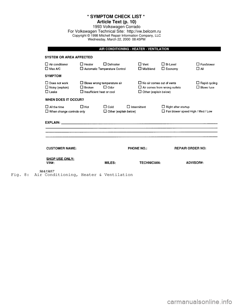
* SYMPTOM CHECK LIST *
Article Text (p. 10)
1993 Volkswagen Corrado
For Volkswagen Technical Site: http://vw.belcom.ru
Copyright © 1998 Mitchell Repair Information Company, LLC
Wednesday, March 22, 2000 08:45PMFig. 8: Air Conditioning, Heater & Ventilation
Page 322 of 920

A/C COMPRESSOR OIL CHECKING
Article Text (p. 8)
1993 Volkswagen Corrado
For Volkswagen Technical Site: http://vw.belcom.ru
Copyright © 1998 Mitchell Repair Information Company, LLC
Wednesday, March 22, 2000 08:47PM
Previa
Without Rear A/C ........... 3.4-4.7 ................ 32-35
With Rear A/C .............. 3.4-4.7 ................ 41-44
Supra ...................... (2) 4.1 ............ (3) 23-27
Tercel ..................... 3.4-4.1 ................ 25-28
T100 ....................... 3.4-4.1 ............ (3) 21-25
4Runner .................... 3.4-4.1 ................ 27-30
Volkswagen
Cabriolet .................... 4.6 .............. 30.0-31.8
Corrado SLC ................ 3.9-4.4 ............ 35.0-36.8
EuroVan
Without Rear A/C ............. 4.6 .............. (4) 34-35
With Rear A/C ................ 8.2 .............. (4) 48-49
Fox .......................... 5.7 .................. 41-42
Golf, GTI & Jetta ............ 3.9 .............. (4) 28-30
Passat ..................... 3.9-4.4 ........ (4) 41.0-42.8
Volvo
240 .......................... 7.4 ................. (5) 26
850
Cold Climates ................ 7.0 ................. (5) 29
Hot Climates ................. 7.0 ................. (5) 26
940 & 960
Sanden SD-510 ................ 4.8 .............. (6) 32-34
Sanden SD-709 ................ 8.5 .............. (6) 32-34
Seiko-Seiki .................. 7.8 .............. (6) 32-34
(1) - Total system capacity, unless otherwise noted.
(2) - Compressor refrigerant oil capacity.
(3) - Use R-134a refrigerant and ND-Oil 8 (Part No. 38899-
PR7-003).
(4) - Use R-134a refrigerant and SP-10 PAG Oil (Part No. G 052
154 A2).
(5) - Use R-134a refrigerant and ZXL 100 PG Oil (Part No.
8708581-7).
(6) - Use R-134a refrigerant and PAG Oil (Part No. 8708581-9).ÄÄÄÄÄÄÄÄÄÄÄÄÄÄÄÄÄÄÄÄÄÄÄÄÄÄÄÄÄÄÄÄÄÄÄÄÄÄÄÄÄÄÄÄÄÄÄÄÄÄÄÄÄÄÄÄÄÄÄÄÄÄÄÄ REFRIGERANT OIL
Only NEW, moisture-free refrigerant oil should be used in the
air conditioning system. This oil is highly refined and dehydrated so
moisture content is less than 10 parts per million. The oil container
must be tightly closed at all times when not in use, or moisture from
the air will be absorbed into the refrigerant oil.
SERVICING PRECAUTIONS
DISCHARGING SYSTEM
Discharge A/C system using approved refrigerant
recovery/recycling equipment. Always follow recovery/recycling
equipment manufacturer's instructions. After refrigerant recovery
Page 337 of 920

A/C COMPRESSOR SERVICING
Article Text
1993 Volkswagen Corrado
For Volkswagen Technical Site: http://vw.belcom.ru
Copyright © 1998 Mitchell Repair Information Company, LLC
Wednesday, March 22, 2000 08:48PM
ARTICLE BEGINNING
1993 AIR CONDITIONING & HEAT
Compressor Servicing
READ THIS FIRST
NOTE: The purpose of this article is to provide GENERAL servicing
overview. For more specific information, refer to the AUTO
A/C-HEAT SYSTEM, MANUAL A/C-HEAT SYSTEM, or HEATER SYSTEM
articles in this section.
NOTE: Due to variety of clutch and shaft seal configurations,
obtain appropriate A/C compressor service tools for
compressor being serviced.
ATSUGI ROTARY VANE CLUTCH COIL R & I
Removal
When replacing compressor clutch, be careful not to scratch
shaft or bend pulley. When removing center bolt, hold clutch disc with
Clutch Holder (KV99231010). Using Hub Puller (KV998VR001), remove
clutch disc. When removing pulley, remove lock nut with Hub Socket
(KV99235160).
Installation
1) Tighten center bolt to 81-104 INCH lbs. (9.1-11.8 N.m).
Tighten lock nut to 21-29 ft. lbs. (29-39 N.m). Using feeler gauge,
ensure clearance between clutch disc and pulley is .012-.024" (.30-.60
mm).
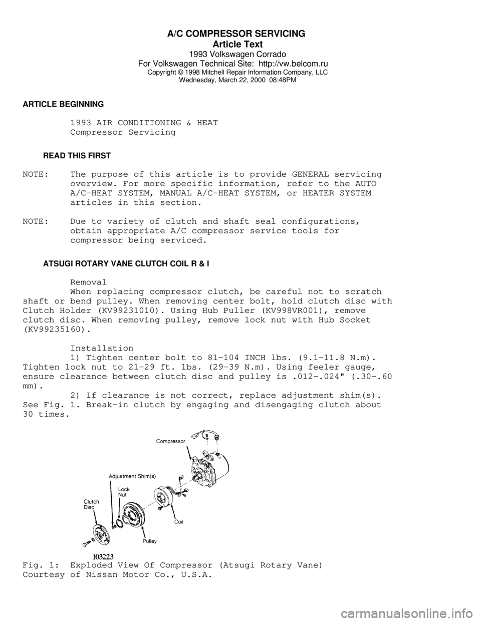
2) If clearance is not correct, replace adjustment shim(s).
See Fig. 1. Break-in clutch by engaging and disengaging clutch about
30 times.Fig. 1: Exploded View Of Compressor (Atsugi Rotary Vane)
Courtesy of Nissan Motor Co., U.S.A.
Page 363 of 920

A/C SYSTEM GENERAL DIAGNOSTIC PROCEDURES
Article Text
1993 Volkswagen Corrado
For Volkswagen Technical Site: http://vw.belcom.ru
Copyright © 1998 Mitchell Repair Information Company, LLC
Wednesday, March 22, 2000 08:48PM
ARTICLE BEGINNING
1993 AIR CONDITIONING & HEAT
A/C General Diagnostic Procedures
Diagnosis is an important first step in A/C system servicing.
To save time and effort, systems should be carefully checked to
identify the causes of poor performance. By using the following
diagnostic charts, defective components or system problems can be
quickly located. To identify problems that are specific to one system,
refer to the repair section of this manual. The charts in this section
apply to all systems.
PREPARATION FOR TESTING
1) Attach Low and High pressure gauges.
2) Start engine and allow to warm up.
3) Set system to COOL and blower to HIGH.
4) Open car doors and hood.
5) Run engine at fast idle for 2-3 minutes.
AIR CONDITIONING SYSTEM PERFORMANCE CHECK
AIR CONDITIONING SYSTEM PERFORMANCE CHECK TABLEÄÄÄÄÄÄÄÄÄÄÄÄÄÄÄÄÄÄÄÄÄÄÄÄÄÄÄÄÄÄÄÄÄÄÄÄÄÄÄÄÄÄÄÄÄÄÄÄÄÄÄÄÄÄÄÄÄÄÄÄÄÄÄÄÄÄÄÄÄPERFORM TESTS: SHOULD BE: IF:
ÄÄÄÄÄÄÄÄÄÄÄÄÄÄÄÄÄÄÄÄÄÄÄÄÄÄÄÄÄÄÄÄÄÄÄÄÄÄÄÄÄÄÄÄÄÄÄÄÄÄÄÄÄÄÄÄÄÄÄÄÄÄÄÄÄÄÄÄÄTemperature Check Temperature Check Is:
* Switch to LOW blower.
* Close doors.
* Check outlet temperature. 35-45
ø F Too warm - Check
control lever
operation, heater
water valve, cooling
system and gauge readings.
ÄÄÄÄÄÄÄÄÄÄÄÄÄÄÄÄÄÄÄÄÄÄÄÄÄÄÄÄÄÄÄÄÄÄÄÄÄÄÄÄÄÄÄÄÄÄÄÄÄÄÄÄÄÄÄÄÄÄÄÄÄÄÄÄÄÄÄÄÄPERFORM TESTS: SHOULD BE: IF:
ÄÄÄÄÄÄÄÄÄÄÄÄÄÄÄÄÄÄÄÄÄÄÄÄÄÄÄÄÄÄÄÄÄÄÄÄÄÄÄÄÄÄÄÄÄÄÄÄÄÄÄÄÄÄÄÄÄÄÄÄÄÄÄÄÄÄÄÄÄVisual Check Visual Check Shows:
* Compressor Quiet with no leaks Noisy - Check belts,
oil level, seals,
gaskets, reed valves.
* Condenser Free of obstructions Blocked - Clean off.
Plugged - Flush or
replace.
* Receiver-Drier Dry and warm to touch Frosty - Check for
restriction, replace
desiccant.
Page 367 of 920

A/C SYSTEM GENERAL DIAGNOSTIC PROCEDURES
Article Text (p. 5)
1993 Volkswagen Corrado
For Volkswagen Technical Site: http://vw.belcom.ru
Copyright © 1998 Mitchell Repair Information Company, LLC
Wednesday, March 22, 2000 08:48PMÃÄÄÄÄÄÄÄÄÅÄÄÄÄÄÄÄÄÄÅÄÄÄÄÄÄÄÄÄÄÄÄÄÄÄÄÄÄÄÄÄÄÄÄÄÄÄÄÄÅÄÄÄÄÄÄÄÄÄÄÄÄÄÄÄÄÄÄÄ´
³ HIGH
³ HIGH ³ Outlet air warm. ³ Compressor ³
³
³ ³ Liquid line very hot. ³ Malfunction ³
³
³ ³ Bubbles in sight glass. ³ or ³
³
³ ³ ³ R-12 Overcharge ³
ÃÄÄÄÄÄÄÄÄÅÄÄÄÄÄÄÄÄÄÅÄÄÄÄÄÄÄÄÄÄÄÄÄÄÄÄÄÄÄÄÄÄÄÄÄÄÄÄÄÅÄÄÄÄÄÄÄÄÄÄÄÄÄÄÄÄÄÄÄ´
³ HIGH
³ HIGH ³ Outlet air slightly cool. ³Large Amount of Air³
³
³ ³ Bubbles in sight glass. ³ of Air & Moisture ³
³
³ ³ ³ in System ³
ÃÄÄÄÄÄÄÄÄÅÄÄÄÄÄÄÄÄÄÅÄÄÄÄÄÄÄÄÄÄÄÄÄÄÄÄÄÄÄÄÄÄÄÄÄÄÄÄÄÅÄÄÄÄÄÄÄÄÄÄÄÄÄÄÄÄÄÄÄ´
³ HIGH
³ HIGH ³ Outlet air warm. ³ Expansion Valve ³
³
³ ³ Evaporator outlet sweating ³ Stuck Open ³
³
³ ³ and frost. ³ ³
ÃÄÄÄÄÄÄÄÄÁÄÄÄÄÄÄÄÄÄÁÄÄÄÄÄÄÄÄÄÄÄÄÄÄÄÄÄÄÄÄÄÄÄÄÄÄÄÄÄÁÄÄÄÄÄÄÄÄÄÄÄÄÄÄÄÄÄÄÄ´
³(1) - If equipped with a low refrigerant charge protection system,
³
³ compressor operation may have stopped.
³
ÀÄÄÄÄÄÄÄÄÄÄÄÄÄÄÄÄÄÄÄÄÄÄÄÄÄÄÄÄÄÄÄÄÄÄÄÄÄÄÄÄÄÄÄÄÄÄÄÄÄÄÄÄÄÄÄÄÄÄÄÄÄÄÄÄÄÄÄÄÙ AIR CONDITIONING GENERAL TROUBLE SHOOTING
CONDITION & POSSIBLE CAUSE
Compressor Not Working
* Compressor clutch circuit open.
* Compressor clutch coil inoperative.
* Poor clutch ground connection.
* Fan belts loose.
* Thermostatic switch inoperative.
* Thermostatic switch not adjusted.
* Ambient temperature switch open.
* Superheat fuse blown.
Excessive Noise or Vibration
* Missing or loose mounting bolts.
* Bad idler pulley bearings.
* Fan belts not tightened correctly.
* Compressor clutch contacting body.
* Excessive system pressure.
* Compressor oil level low.
* Damaged clutch bearings.
* Damaged reed valves.
* Damaged compressor.
Insufficient or No Cooling; Compressor Working
* Expansion valve inoperative.
* Heater control valve stuck open.
* Low system pressure.
* Blocked condenser fins.
* Blocked evaporator fins.
* Vacuum system leak.
* Vacuum motors inoperative.
* Control cables improperly adjusted.
Page 377 of 920

A/C-HEATER SYSTEM - MANUAL
Article Text (p. 2)
1993 Volkswagen Corrado
For Volkswagen Technical Site: http://vw.belcom.ru
Copyright © 1998 Mitchell Repair Information Company, LLC
Wednesday, March 22, 2000 08:49PM
* Disable air bag system before servicing any air bag system or
steering column component. See DISABLING & ACTIVATING AIR BAG
SYSTEM.
* Because of critical operating requirements of system, DO NOT
attempt to service any air bag system component.
* DO NOT leave air bag parts unattended. Install parts in vehicle
immediately after obtaining.
* DO NOT use air bag components that have been dropped from height
of more than 18 inches.
* DO NOT allow chemical cleaners, oil and grease to contact vinyl
covering on air bag unit.
* DO NOT place stickers or covers on steering wheel.
* Always disable air bag system before performing electric welding
on vehicle.
* Air bag system can only be tested using Diagnostic Tester (VAG
1551) and Multimeter (US-1119). Never use test light on air bag
system.
* DO NOT expose air bag unit to temperatures greater than 194øF
(90
øC).
DISABLING & ACTIVATING AIR BAG SYSTEM
WARNING: System voltage is retained for about 20 MINUTES after system
is deactivated. Wait about 20 MINUTES after system is
disabled before servicing, as air bag may accidentally
deploy, causing personal injury.
Disabling & Activating System
To disable system, disconnect negative battery cable. Wait 20
MINUTES before working on vehicle. To activate system, reconnect
negative battery cable. Verify system is functioning properly. See
SYSTEM OPERATION CHECK.
CAUTION: When battery is disconnected, radio will go into anti-theft
protection mode. Obtain radio anti-theft protection code
from owner prior to servicing vehicle.
DESCRIPTION
The air conditioning system is a cycling clutch type.
Compressor is cycled on and off by a thermostatic switch to maintain
constant cooling rate. System components include evaporator, expansion
valve, receiver-drier, control panel and condenser. A dual-pressure
switch includes a high-pressure cut-out switch and a low-pressure cut-
out switch.
Control panel includes 3 rotary knobs over 2 push buttons.
See Fig. 1. Left knob controls the fan and increases fan speed when
turned clockwise. Center knob is the temperature control and increases
heat by turning clockwise. Right knob controls air distribution.
The 2 push buttons are ON/OFF switches controlling A/C. Left
button controls normal A/C (outside air). Right button gives maximum
A/C using recirculating air. See Fig. 1.
Page 393 of 920

ABBREVIATIONS
Article Text
1993 Volkswagen Corrado
For Volkswagen Technical Site: http://vw.belcom.ru
Copyright © 1998 Mitchell Repair Information Company, LLC
Wednesday, March 22, 2000 08:49PM
ARTICLE BEGINNING
GENERAL INFORMATION
COMMONLY USED ABBREVIATION
"A" ABBREVIATION TABLE
"A" ABBREVIATION TABLEÚÄÄÄÄÄÄÄÄÄÄÄÄÄÄÄÄÄÂÄÄÄÄÄÄÄÄÄÄÄÄÄÄÄÄÄÄÄÄÄÄÄÄÄÄÄÄÄÄÄÄÄÄÄÄÄÄÄÄÄÄÄÄÄÄÄÄÄÄ¿
³ABBREVIATION
³DEFINITION ³
ÃÄÄÄÄÄÄÄÄÄÄÄÄÄÄÄÄÄÅÄÄÄÄÄÄÄÄÄÄÄÄÄÄÄÄÄÄÄÄÄÄÄÄÄÄÄÄÄÄÄÄÄÄÄÄÄÄÄÄÄÄÄÄÄÄÄÄÄÄ´
³A
³Amperes ³
³A/C
³Air Conditioning ³
³A/T
³Automatic Transmission/Transaxle ³
³AAP
³Auxiliary Accelerator Pump ³
³AB
³Air Bleed ³
³ABCV
³Air Bleed Control Valve ³
³ABDC
³After Bottom Dead Center ³
³ABRS
³Air Bag Restraint System ³
³ABS
³Anti-Lock Brake System ³
³AC
³Alternating Current ³
³ACC
³A/C Clutch Compressor ³
³ACCS
³A/C Cycling Switch ³
³ACCUM
³Accumulator ³
³ACCY
³Accessory ³
³ACT
³Air Charge Temperature Sensor ³
³ACV
³Thermactor Air Control Valve ³
³ADJ
³Adjust or Adjustable ³
³ADV
³Advance ³
³AFS
³Airflow Sensor ³
³AI
³Air Injection ³
³AIR or A.I.R.
³Air Injection Reactor ³
³AIS
³Air Injection System ³
³ALCL
³Assembly Line Communications Link ³
³ALDL
³Assembly Line Diagnostic Link ³
³ARC
³Automatic Ride Control ³
³ASCD
³Automatic Speed Control Device ³
³ASCS
³Air Suction Control Solenoid ³
³ASD
³Auto Shutdown ³
³ASDM
³Air Bag System Diagnostic Module ³
³ASV
³Air Suction Valve ³
³ATC
³Automatic Temperature Control ³
³ATDC
³After Top Dead Center ³
³ATF
³Automatic Transmission Fluid ³
³ATS
³Air Temperature Sensor ³
³AXOD
³Automatic Transaxle Overdrive ³
³Abs.
³Absolute ³
³Accy.
³Accessory ³
³Alt.
³Alternator or Altitude ³
³Amp.
³Ampere ³
Page 579 of 920

FUSES & CIRCUIT BREAKERS
Article Text
1993 Volkswagen Corrado
For Volkswagen Technical Site: http://vw.belcom.ru
Copyright © 1998 Mitchell Repair Information Company, LLC
Wednesday, March 22, 2000 09:11PM
ARTICLE BEGINNING
1990-94 ELECTRICAL
Volkswagen Fuses & Circuit Breakers
Corrado
FUSES & CIRCUIT BREAKERS
FUSE PANEL LOCATION
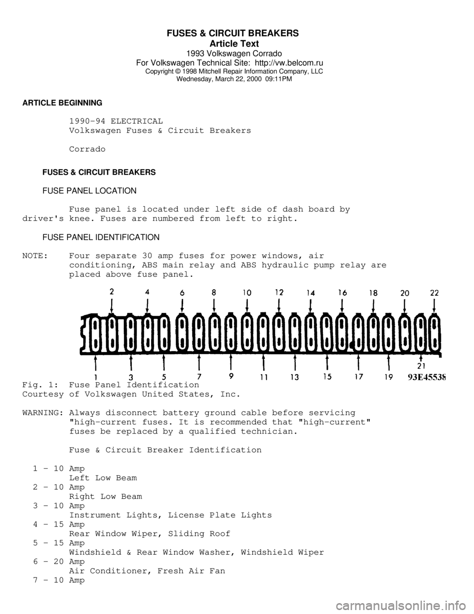
Fuse panel is located under left side of dash board by
driver's knee. Fuses are numbered from left to right.
FUSE PANEL IDENTIFICATION
NOTE: Four separate 30 amp fuses for power windows, air
conditioning, ABS main relay and ABS hydraulic pump relay are
placed above fuse panel.Fig. 1: Fuse Panel Identification
Courtesy of Volkswagen United States, Inc.
WARNING: Always disconnect battery ground cable before servicing
"high-current fuses. It is recommended that "high-current"
fuses be replaced by a qualified technician.
Fuse & Circuit Breaker Identification
1 - 10 Amp
Left Low Beam
2 - 10 Amp
Right Low Beam
3 - 10 Amp
Instrument Lights, License Plate Lights
4 - 15 Amp
Rear Window Wiper, Sliding Roof
5 - 15 Amp
Windshield & Rear Window Washer, Windshield Wiper
6 - 20 Amp
Air Conditioner, Fresh Air Fan
7 - 10 Amp