Page 1153 of 1254
HEADLAMP
-
Dimdip lamp
System -
Operation
When ignition
switch is
in
the "ON" position
with the lighting
switch in the "1ST"
oosition. the headlamo low
beam comes on
dimly to
function as a clearance lamp. Lighting switch opera-
tions other than the above are the same as conventional fioht
svstems.
lgnition switch OFF or ACC ON
Lighting switch OFF
1ST
2ND
OFF 1ST
2ND
B c B Bc Bc B(.
Bc
Headlamp High
beam XXo Xxo Xo XX XX
o X
Low beam X
X XX
X X
Xo XX XX XXX x
o X
Dimp-dip
(Low b€am) X
x XXX XXXX Xx X xXXX
Clearance and tail lamo
Xx X
o o XX X
oo o
License and instrument
illumination lamp X
Xx
o oXX X o o
o
O: Lamo "ON"
X: Lamo "OFF"
Cl Added
functions
Schematic
I GNJ I]
ON SWJ ICH
0N o. START AAITERY
5 O] I1'O]
P
LJGHT 9
CON IROL UNI I
?
it
]? L]GIlT]NG
SWJ TCH
To c
€a.ance, ta i I
I iccnse
amps
HI GH 8EAI1
J NO]
CAIOR
MEL6/78
EL42
Page 1155 of 1254
HEADLAMP
-
Headlamp Aiming
Control-
Description
o The
vertical direction
of the headlamp prolection
can be adjusted
lrom inside the vehicle
to prevent
lhe headlight beam
axis from
facing upward
due to a change
in the number of
occupants and load
conditions in
the vehicle.
Battot^y
En I
a.ocd
gont l6n A
Rcvc
na In9
t cIlv
Cont Inu lty
Fon
/ard
.e lay
Almlno
gw I tc6
No cont Inu lty
(Wh lt6 po.t
lor,
SENS0R (Rotat
Ino
po.t I od
No
cont Inu lty
(Wh ltc po.t
I or,
SENSOR (RotEt
Ina
por-t I od
I Thoi. trto.
AI I1I NG I1OTOR
UNI T (R.
I-t )
Rcve.a Ino
rc l!y
Cont lnu lty
Jhc nn I
ator
AI MI NG I'IOTOR
UNI T (L.
I{ )
EL-44
Page 1159 of 1254
HEADLAMP
-
Headlamp Aiming
Control-
A Cil
Lighting swrlch lsl
5r
ts EI'H)
mtri
mti Troublediagnoses
SYMPTOM: Headlamp
aiming does not operate.
E
Check 10A fse
al luse
block.
(Refer to "POWER
SUPPLY
ROUTING.")
POWER
SUPPLY CIRCUIT
CHECK (For
aiming switch)
Check if
12 volts
exist between
terminals O and
aO.
AIMING SWITCH CHECK
Check continuity between termi-
nals at each switch position.
GROUND CIRCUIT
CHECK
FOR AIMING MOTOR
Check continuity between termi-
nals rj)
and body grround.
Continuity exists ... O.K. Bepair
harness between
aiming
motor and body ground.
POWER SUPPLY CIRCUIT
CHECK
(For aiming motor unit)
Check il 12 volts
exist between
terminats 'O,
@, @, @ and
o Volt-
meter
termina Voltage
[V]Aiming
switch
posrtron
o Approx.
12"0"
o "0"
.;\ Approx.
12"1"
0 "1"
o Approx.
12
0
o Approx.
12,.3,,
0 "3"Check
harness
between aimjng
switch and aiming motor
unit.
EL.48
Page 1161 of 1254
HEADLAMP
lJp and down adlustrng Aiming
Adjustment (Cont'd)
LOW BEAM
1 . Turn
headlamp low beam on.
2. Use adjusting screws lo perform
aiming adjustment.
o First
tighten the adiusting screw
all the way and then make
adiustment by loosening the screw.
a. Adiust
headlamps so that main axis of light is parallel
to
center line ol body and is aligned with point
P shown in
illustration.
b. Figure to the left shows headlamp aiming pattern
for driv-
ing on right
side of road;
for
driving on left side of road,
aiming pattern
is reversed.
c. Dotted
lines in illustration show c€nter of headlamp.
"H": Horizontal c€nter line of headlamps
"W.": Distanc€ between each headlamp
center
"L": 5,fi)O mm (196.85
in)
"C": 53 mm (2.09
in)
Varticalcantgrlane
ahrsd of haedlamp, Heighr
ol -
q$ =
acceenere nrruce
EL-50
Page 1199 of 1254
HORN.
CIGARETTE LIGHTER
AND
CLOCK
Wiring Diagram
c)
t-,
--Tl
R/r -fl
I
el i;
c "-n E---[E
=
t-l
n
cc
LI
.9
c
5\ E
E ltil
Ei
rl l
r )----(
I
!
L-'
l' i'l
TT
r)
al
Yzz
;;," >l.
_ I
Zq-_-F;B
5;Fflil iL!:G".
- 9rrl
/11 6r
19'i,
liJ lir
'e,, t0116INq-ION
NETER
]LO'K I LLU'1I NATI
ON
: o----)--€r-,.; [.0'K
I LLUIlI NAT:
ON
r
-;^
c oc
EL-88
Page 1202 of 1254

REAR
WINDOW DEFOGGER
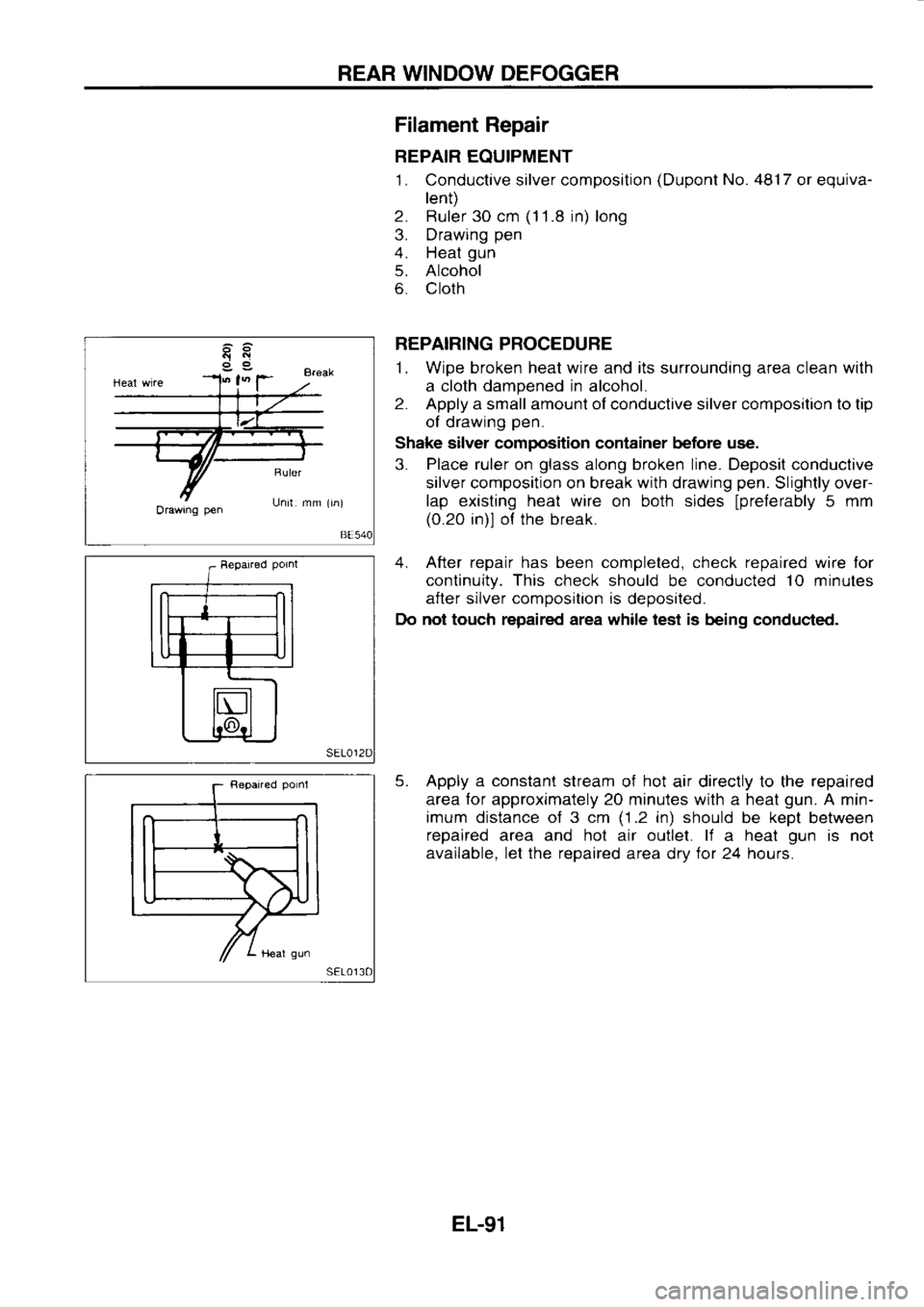
Orawrng pen Filament
Repair
REPAIR EQUIPMENT
1. Conductive silver composition (Dupont
No. 48'17
or equiva-
lent)
2. Ruler 30 cm (1
1 .8 in) long
3. Drawing pen
4. Heat gun
5. Alcohol
6. Cloth
REPAIRING PROCEDURE
1. Wipe broken heat wire and its surrounding area clean with
a cloth dampened
in
alcohol.
2. Apply
a small amount of conductive silver composition to tip
ol drawing pen.
Shake silver composition container before use.
3. Place
ruler
on glass
along broken line. Deposil conductive
silver composition on break with drawing pen.
Slightly over-
lap existing heat wire
on both sides
lprelerably 5
mm
(0.20 in)l ol the break.
4. After repair has been completed, check repaired wire lor
continuity. This check
should be conducted 10
minutes
after silver composition
is
deposited.
Do not touch repaired area while test is
being conduc{ed.
5. Apply a constant
stream of hot
air directly to the repaired
area for approximately 20 minutes with a heat gun.
A min-
imum distance of 3 cm (1.2
in) should
be kept
between
repaired area and hot air outlet. li
a heat gun
is not
available. let the repaired
area drv for
24 hours.
EL-91
Page:
< prev 1-8 9-16 17-24