Page 692 of 738
Downloaded from www.Manualslib.com manuals search engine 54-196CHASSIS ELECTRICAL - Rear Window Defogger
CIRCUIT DIAGRAM
F'JSIBLELINK@
3R-I3
(c-01)22B-h,-----------___.
3R-E
3B-F
38-F
IGNITIONIGNIlSWITCH(IG2)SWITC
- -
2L-BI
28-h
J’Bp
L-RIB-k
DEFOGGER
RELAY
(c-06x)
MFI SYSTEM3;:(c-66)-
REMOTE#JJ&LLED
GNIn
B
!B
INGENE(IGl)(L TE
B-W(F>I
7mCHARGINGI(D-45)
30
I
e-CHARGINGT
(c-15)
52
TORINAL)
10
'57 :1I
59 $2
NOTE:l:VEHICLES WITHOUTTHEFT-ALARM SYSTEM.22:VEHICLES WITHTHEFT-ALARM SYSTEM.
HR13M02AA
1 TSB Revision
Page 693 of 738
Downloaded from www.Manualslib.com manuals search engine CHASSIS ELECTRICAL - Rear Window Defogger
ii
2W-B
5W-BHORN
‘J/B,.1 (c-68)
(F>R-B(F>R-I
DOOR LIGHT AND LUGGAGE
COMPARTMENT LIGHT
:I,
,HEADLIGHT.FOG LIGHT.TAILLIGHT.PARKING/SIDE
MARKER LIGHT
AND LICENSE
PLATE LIGHT
69
10A\/
11------ A/1R-Y
r R
(c-70)
/L-R
cc-65)
f
i
I
,E
2B
FUSIBLE LINKa
I
1,,2 ,,l/\,--(A-11X) (
2B-F
IOD OR STRAGE
CONNECTOR
DEFOGGER
SWITCH
iD-os)
i
my54
B-L
R-B
9I16"AA\(
45 DATA LINK CONNECTOR
B(c-79)
i
L-R
V
1'4
:;fE-$;T (B-Y).$;;EESAND
2B
,(D-41)B-Y
27
RHEOSTAT
2B
h
n
NOTE:l:VEHICLES WITHOUTTHEFT-ALARM SYSTEM.:2:VEHICLES WITHTHEFT-ALARM SYSTEM.
2B-k
\6
IND(UN
TAILLIGHT RELAY
q-
:;&"A'""
J/B
7L IIG-W
I
8cc-71)
p@
G-W4
Ed.ELC-4A/T
'i;$$SAND (G-W)
2,,3
HR13M02AB
TSB Revision
Page 695 of 738
Downloaded from www.Manualslib.com manuals search engine CHASSIS ELECTRICAL - Rear Window Defogger54-199
LJ
FUSIBLE LINKa
I
(c-83)L
(F>R-B(F>R-i
DOOR LIGHT AND LUGGAGECOMPARTMENF
.HEADLIGHT,FOG LIGHT.TAILLIGHT.PARKING/SIDE
MARKER LIGHT
AND LICENSE
PLATE LIGHTr
IL-R
(C-65)112P
$
4
B
E
F
2B=
/ - 12B-
IOD OR STRAGE
CONNECTOR
DEFOGGER
SWITCH
(D-06)i
Al
5 DATA LINK CONNECTOR
)FF ‘T[
2B
2B
2B-
6
IN
I
TAILLIGHT RELAY
I1.25R-W
l&&CATED
0%
15A
G-W,,6 (c-69)
J/B\
,\,G-W8 (c-71)
W8(D-44)
1
(D-41).ELC-4A/T
'&;&AND (G-W)),,31
:aFRONT SIDE (c-83)
B-Y
RHEOSTAT
HR13M03AB
TSB Revision
Page 696 of 738

Downloaded from www.Manualslib.com manuals search engine 54-200CHASSIS ELECTRICAL - Rear Window Defogger
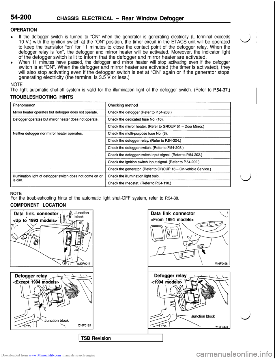
OPERATIONl
If the defogger switch is turned to “ON” when the generator is generating electricity (L terminal exceeds
10 V.) with the ignition switch at the “ON” position, the timer circuit in the ETACS unit will be operated
to keep the transistor “on” for 11 minutes to close the contact point of the defogger relay. When the
defogger relay is “on”,the defogger and mirror heater will be activated. Moreover, the indicator lightof the defogger switch is lit to inform that the defogger and mirror heater are activated.
lWhen 11 minutes have passed, the defogger and mirror heater will stop activating even if the defoggerswitch is at “ON”. When the defogger and mirror heater are activated (the timer is activated), they
will also stop activating even if the defogger switch is set at “ON” again or if the generator stops
generating electricity (the terminal is 3.5 V or less.)
NOTE
The light automatic shut-off system is valid for the illumination light of the defogger switch. (Refer to
P.54-37.)
TROUBLESHOOTING HINTS
NOTE
For the troubleshooting hints of the automatic light shut-OFF system, refer to P.54-38.
COMPONENT LOCATION
Datalink. connector
216FO125
Data link connector
\V16FO496 1
es.-‘) blocky,6Fww
1 TSB Revision
Page 700 of 738
Downloaded from www.Manualslib.com manuals search engine
INSPECTION
I I IIQ!-hh&Connect battery power source to terminal 5. Check circuitbetween terminals with terminal 3 grounded.
lBFO206cl994 models>00002410
54-204CHASSIS ELECTRICAL - Rear Window Defogger
~1
~1994 models>Connect battery power source to terminal 1. Check circuit
between terminals with terminal 3 grounded.
L---i00002411
TSB Revision
Page 702 of 738
Downloaded from www.Manualslib.com manuals search engine CHASSIS ELECTRICAL - Theft-alarm Svstem
TROUBLESHOOTING(UP TO 1993 MODELS)
CIRCUIT DIAGRAM
HEADLIGHT
RELAY
0---------_
IGNITIONIGNITIONSWITCH(IG1)SW1 TCH(ACC)
63
10A
0
15A
c-77)16(c-80)
0.85, B-W
FJ$
B-W
----------1
xSOCI
0.85L
L
Lt
2R-L12R-L1(R.2
’ I
R-B
L
8
3520 53,\---------__ --------__
\II
1"2 /2R ;I----- --A3‘3
1.25R
0
1.25R
3_----,,6
1625R,8,C
I---.*HI
Y
+
LI
E
-B
1A
0.85R-W
(c-01)
0.85R-W
jLIGHTAUTOMATIC 0SHUT-OFF
UNIT
.----------------------
lO(c-65) ETACS UNITI
- -
E54#
G#~O L[r
R-c
R-c
nr-
- -
(LH)(RH)
DOOR TWITCH
;zk77)(c-80)(c-82) (E-15)(m) (E-21)
gj 1~~~~~~~~~
HR15MOOAA
1 TSB Revision
Page 704 of 738
Downloaded from www.Manualslib.com manuals search engine 54-208CHASSIS ELECTRICAL - Theft-alarm System
CIRCUIT DIAGRAM (CONTINUED)
LIGHT
AUTOMATIC
SHUT-OFF UNIT IGNITIONKEY
SW ITCH(ST)I#$!;'"
2B-Y0B-YyM/TA/T,
2B-Y
(c-31) v2LM/T "
t
A/T
2B-Y
,4may1j---1 1 j
L.mI.b ------____--___ - ------ - ----- -- ---- --$V??ER/
r77
OFi-,,ON/I\,/
2B-Y 2\G-B
(A-67) 2(3,J---_II ,-rn /TIM/T *A/Ta
I
G-E3
(1992 MODEL> *cl993 MODEL>
t
G-Er\3 ;
,
3LG-BG-B 3I
SE"
/\
POSITIONN SWITCHOFF-,:ONl(c-64)
6'1
LG-E
B-LY-
\A/T *
I
M/T
1
I
xm-STARTER
RELAY
l(c-56)t8E
L-2%13q 1 ‘-:liq2E
GNDV
2B
HR15MOOBAI
TSB Revision
Page 705 of 738
Downloaded from www.Manualslib.com manuals search engine CHASSIS ELECTRICAL - Theft-alarm System54-209 ~
i
FUSIB ELINK 6
'T 2,,-B ,
5W-BJ/B,,l (c-68)\
T,,
RBI 11;;‘I‘I
' THEFT-ALARMi HORN RELAYI
I(c-72)II
R-E
L
G-E
-0FFJ
3
14(c-76)
R-E
IIiA
(c-78)
L-G1
G-R
_____-_________--
18G-E
L
DIODE
c-12
R-E
L-G
ETACS UNIT
I(c-66) 58
G-E
HORN(LH) (RH)mi-HORNCLOCK
SPRING
GR
(12E
1
HORN
SWITCH
28
d- --z- -
qE!GFm KFn (A-47) (A-48) (A-49) @FEZ) mJ2)(c-57)
II Ei q a q q p---qpq9 ~10~11~~12/13~14115116l1?~~16~19
(c-68) (c-12) (c-76) 673(c-80)
/EiJq @ mmE=FL
HR15MOOBB
TSB Revision