1993 DODGE TRUCK low oil pressure
[x] Cancel search: low oil pressurePage 390 of 1502
INSTRUMENT
PANEL
AND
GAUGES
8E - S
J938E-34
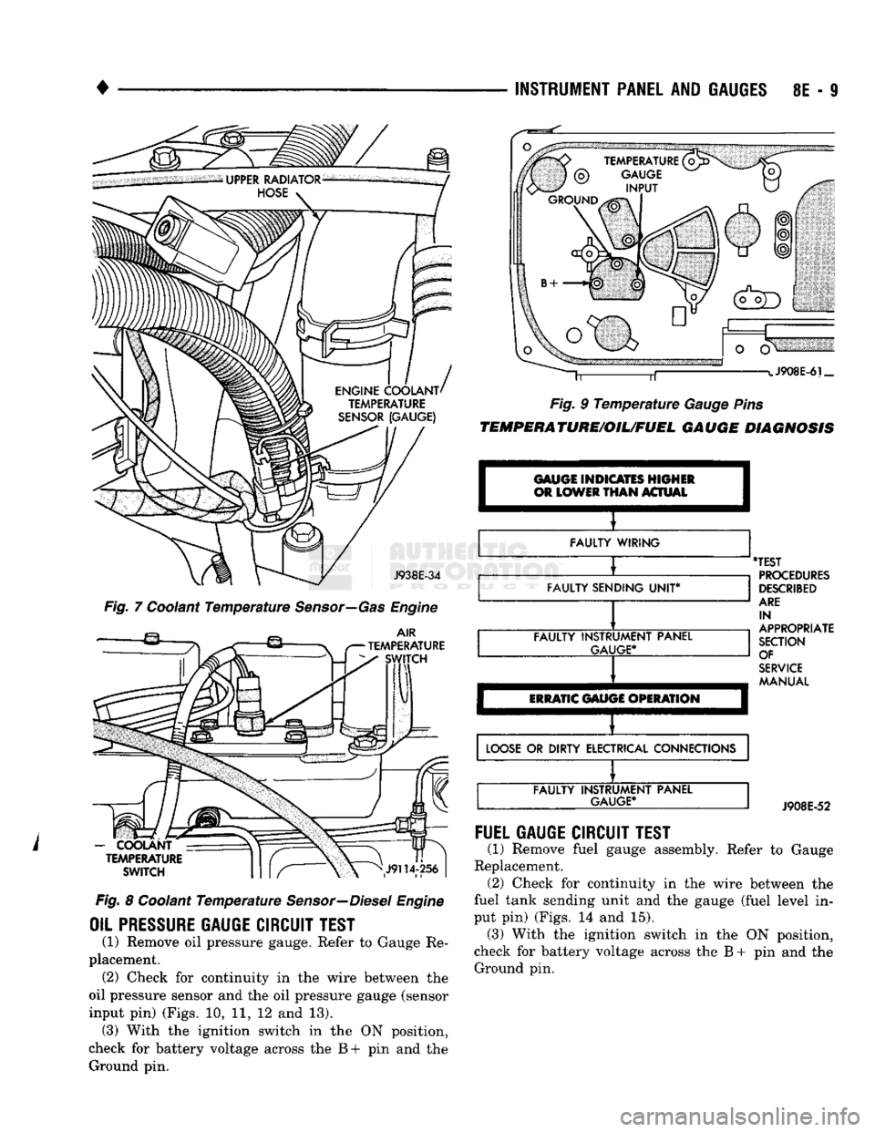
Fig. 7 Coolant Temperature Sensor—Gas Engine
AIR
TEMPERATURE SWITCH
-
COOLANT TEMPERATURE
SWITCH
Fig. 8 Coolant Temperature Sensor—Diesel Engine
OIL PRESSURE
GAUGE
CIRCUIT
TEST
(1) Remove oil pressure gauge. Refer to Gauge Re
placement. (2) Check for continuity in the wire between the
oil pressure sensor and the oil pressure gauge (sensor
input pin) (Figs. 10, 11, 12 and 13). (3) With the ignition switch in the ON position,
check for battery voltage across the B+ pin and the Ground pin. J908E-6i_
Fig. 9 Temperature Gauge Pins
TEMPERATURE/OIL/FUEL
GAUGE
DIAGNOSIS
GAUGE INDICATES HIGHER
OR
LOWER
THAN
ACTUAL I
FAULTY WIRING
FAULTY SENDING
UNIT*
FAULTY INSTRUMENT PANEL
GAUGE*
ERRATIC
GAUGE OPERATION
'TEST
PROCEDURES
DESCRIBED
ARE
IN
APPROPRIATE
SECTION OF
SERVICE
MANUAL
LOOSE
OR DIRTY ELECTRICAL CONNECTIONS FAULTY INSTRUMENT PANEL
GAUGE*
J908E-52
FUEL
GAUGE
CIRCUIT
TEST
(1) Remove fuel gauge assembly. Refer to Gauge
Replacement. (2) Check for continuity in the wire between the
fuel tank sending unit and the gauge (fuel level in
put pin) (Figs. 14 and 15). (3) With the ignition switch in the ON position,
check for battery voltage across the B + pin and the Ground pin.
Page 394 of 1502
INSTRUMENT PANEL
AND
GAUGES
8E - 13
INSTRUMENT
PANEL MAP LAMP
BRACKET
HEADLAMP
SWITCH
CLUSTER
ASSEMBLY
HEADLAMP
SWITCH
MOUNTING
NUT CARGO LAMP
SWITCH
BEZEL
AND
APPLIQUE
HEADLAMP
KNOB
AND
STEM
BRACKET-AAAP LAMP
MOUNTING
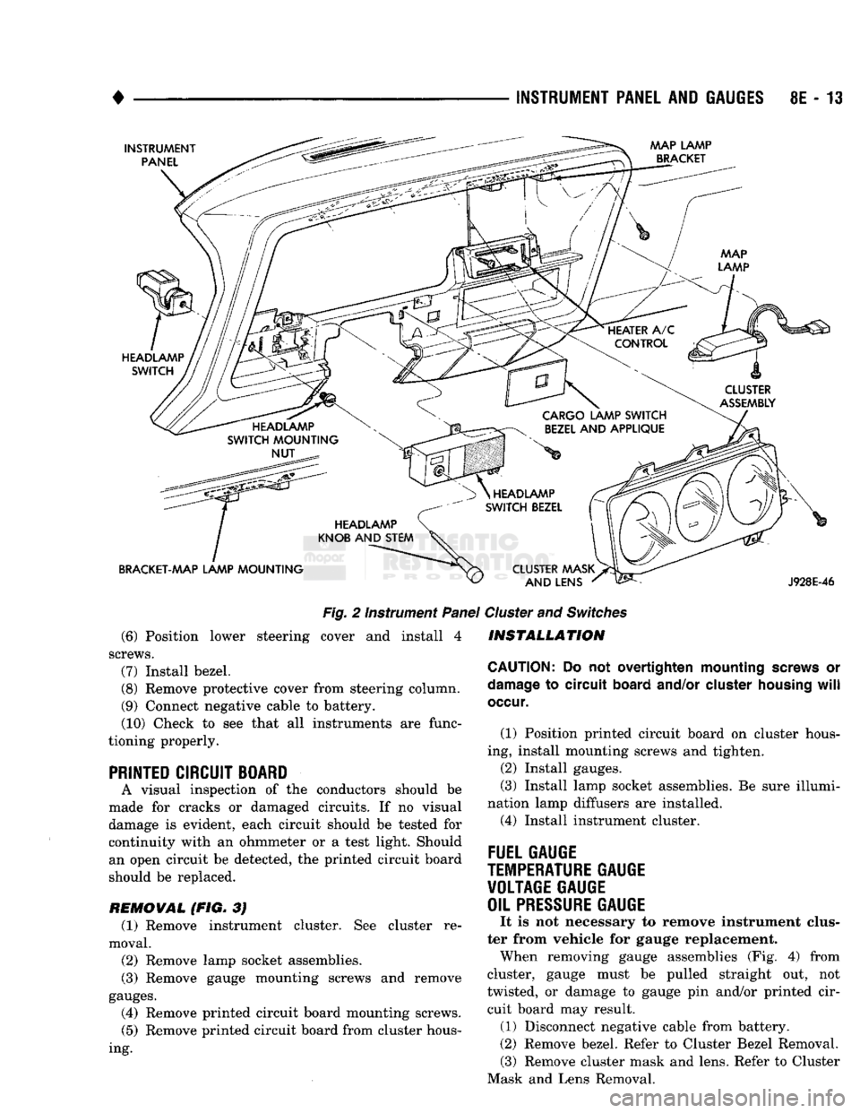
Fig.
2 Instrument
Panel
(6) Position lower steering cover and install 4
screws.
(7)
Install bezel.
(8)
Remove protective cover from steering column.
(9) Connect negative cable to battery. (10) Check to see that all instruments are func
tioning properly.
PRINTED CIRCUIT BOARD
A visual inspection of the conductors should be
made for cracks or damaged circuits. If no visual
damage is evident, each circuit should be tested for continuity with an ohmmeter or a test light. Should an open circuit be detected, the printed circuit board
should be replaced.
REMOVAL (FIG. 3J (1) Remove instrument cluster. See cluster re
moval.
(2)
Remove lamp socket assemblies.
(3) Remove gauge mounting screws and remove
gauges.
(4) Remove printed circuit board mounting screws.
(5)
Remove printed circuit board from cluster hous
ing.
HEADLAMP
SWITCH
BEZEL
CLUSTER MASK AND LENS
J928E-46
Cluster
and
Switches
INSTALLATION
CAUTION:
Do not overtighten mounting
screws
or
damage
to circuit
board
and/or
cluster
housing
will
occur.
(1) Position printed circuit board on cluster hous
ing, install mounting screws and tighten.
(2)
Install gauges.
(3) Install lamp socket assemblies. Be sure illumi
nation lamp diffusers are installed. (4) Install instrument cluster.
FUEL GAUGE
TEMPERATURE
GAUGE VOLTAGE GAUGE
OIL
PRESSURE
GAUGE
It is not necessary to remove instrument clus
ter from vehicle for gauge replacement. When removing gauge assemblies (Fig. 4) from
cluster, gauge must be pulled straight out, not
twisted, or damage to gauge pin and/or printed cir cuit board may result. (1) Disconnect negative cable from battery.
(2)
Remove bezel. Refer to Cluster Bezel Removal. (3) Remove cluster mask and lens. Refer to Cluster
Mask and Lens Removal.
Page 396 of 1502
•
INSTRUMENT PANEL
AND
GAUGES
8E - 15
PRND21 INDICATOR
REMOVAL
(1) Remove bezel. Refer to Cluster Bezel Removal.
(2)
Remove cluster mask and lens. Refer to Cluster
Mask and Lens Removal. (3) Remove cluster assembly. Refer to Instrument
Cluster Removal. (4) Remove screws attaching PRND21 mechanism
to cluster housing.
(5)
Remove PRND21 mechanism.
INSTALLATION (1) Position PRND21 mechanism to cluster hous
ing. (2) Install mounting screws.
(3)
Install cluster assembly. (4) Install mask-lens.
(5)
Install bezel.
LAMP BULBS
CLUSTER ILLUMINATION LAMPS TURN SIGNAL INDICATOR LAMPS
LOW OIL PRESSURE INDICATOR LAMP
HIGH BEAM INDICATOR LAMP CHECK ENGINE LAMP
SEAT BELT WARNING LAMP
REMOVAL (1) Disconnect negative cable from battery.
(2) Remove instrument cluster. See cluster re
moval.
(3)
Twist lamp socket assembly and remove from
printed circuit board. (4) Remove bulb from socket.
INSTALLATION (1) Install bulb into socket.
(2) Install socket assembly into printed circuit
board.
(3)
Position cluster into place in panel. See cluster
installation. (4) Connect battery negative cable.
LAMP BULB REPLACEMENT—MESSAGE CENTER
REMOVAL (1) Disconnect battery negative cable.
(2) Remove instrument cluster bezel assembly. Re
fer to Instrument Cluster removal.
(3)
Twist lamp socket assembly and remove from
printed circuit board. (4) Remove bulb from socket.
INSTALLATION (1) Install bulb into socket assembly. (2) Install lamp socket assembly into printed cir
cuit board.
(3)
Install Instrument Cluster bezel assembly to
instrument panel. Refer to Instrument Cluster instal
lation.
(4) Connect negative cable from battery.
FOUR WHEEL DRIVE INDICATOR LAMP (1) Pull bulb and socket assembly from rear of
housing. (2) Remove bulb from socket.
(3)
Reverse removal procedures to install.
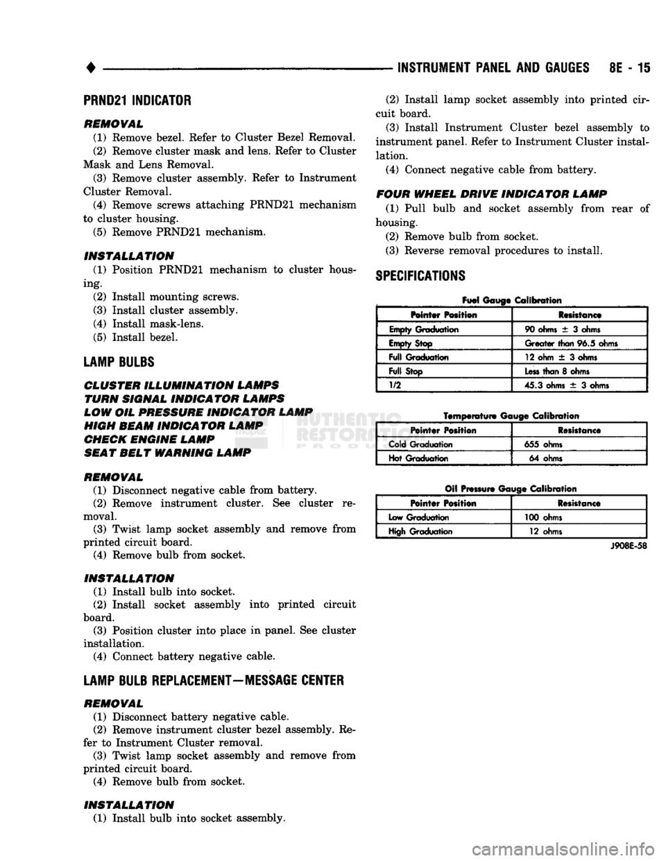
SPECIFICATIONS
Fuel
Gauge Calibration
Mntar Position Resistance
Empty Graduation 90
ohms
± 3
ohms
Empty Stop
Greater
than
96.5 ohms
Full
Graduation 12 ohm
± 3
ohms
Full
Stop
Less
than
8
ohms
1/2
45.3 ohms
± 3
ohms
Temperature
Gauge
Calibration
Pointer
Position Resistance
Cold Graduation 655 ohms
Hot Graduation 64 ohms
Oil Pressure Gauge Calibration
Pointer
Position Resistance
Low Graduation 100 ohms
High Graduation 12 ohms
J908E-58
Page 454 of 1502
•
LAMPS
8L - 11
BULB
APPLICATION
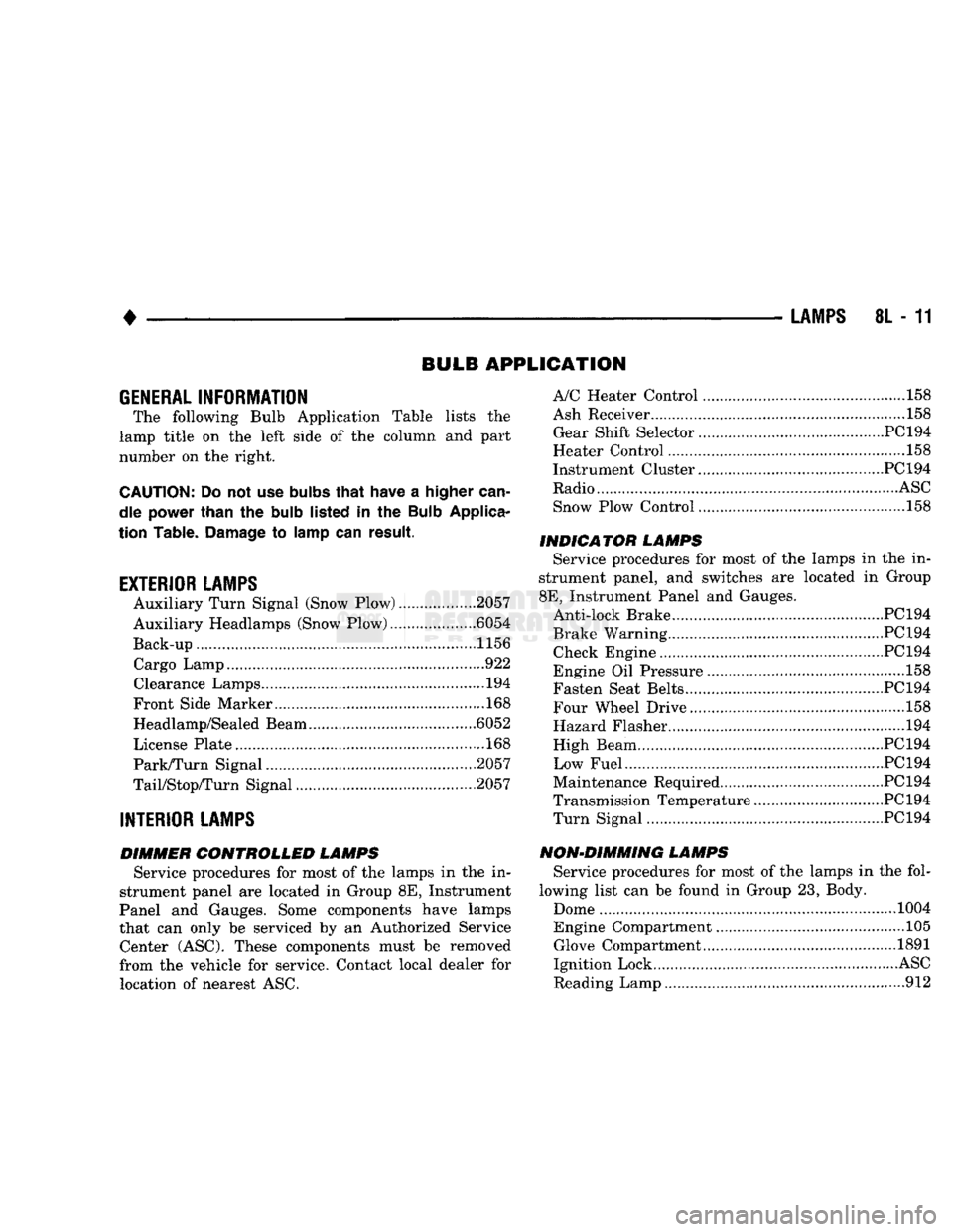
GENERAL
INFORMATION
The following Bulb Application Table lists
the
lamp title
on the
left side
of the
column
and
part
number
on the
right.
CAUTION:
Do not use
bulbs
that
have
a
higher
can
dle power than
the
bulb
listed
in the
Bulb
Applica
tion Table.
Damage
to
lamp
can
result.
EXTERIOR LAMPS
Auxiliary Turn Signal (Snow Plow) 2057
Auxiliary Headlamps (Snow Plow) .6054
Back-up....................... .......1156 Cargo Lamp..
922
Clearance Lamps
194
Front Side Marker
168
Headlamp/Sealed Beam .6052
License Plate
168
Park/Turn Signal 2057
TaiyStop/Turn Signal ...2057
INTERIOR LAMPS
DIMMER CONTROLLED LAMPS Service procedures
for
most
of the
lamps
in the in
strument panel
are
located
in
Group
8E,
Instrument
Panel
and
Gauges. Some components have lamps
that
can
only
be
serviced
by an
Authorized Service Center (ASC). These components must
be
removed
from
the
vehicle
for
service. Contact local dealer
for
location
of
nearest
ASC.
A/C Heater Control
158
Ash Receiver
..158
Gear Shift Selector...........................................PC194
Heater Control
158
Instrument Cluster.. PC 194
Radio
ASC
Snow Plow Control
.158
INDICATOR LAMPS Service procedures
for
most
of the
lamps
in the in
strument panel,
and
switches
are
located
in
Group
8E,
Instrument Panel
and
Gauges. Anti-lock Brake PC194
Brake Warning PC194 Check Engine PC194
Engine
Oil
Pressure
158
Fasten Seat Belts.. PC 194 Four Wheel Drive ....158
Hazard Flasher
194
High Beam PC194
Low Fuel....... JPC194
Maintenance Required PC 194
Transmission Temperature ..PC 194 Turn Signal PC194
NON-DIMMING LAMPS Service procedures
for
most
of the
lamps
in the
fol
lowing list
can be
found
in
Group
23,
Body.
Dome
1004
Engine Compartment ...105 Glove Compartment....
1891
Ignition Lock
ASC
Reading Lamp
912
Page 513 of 1502
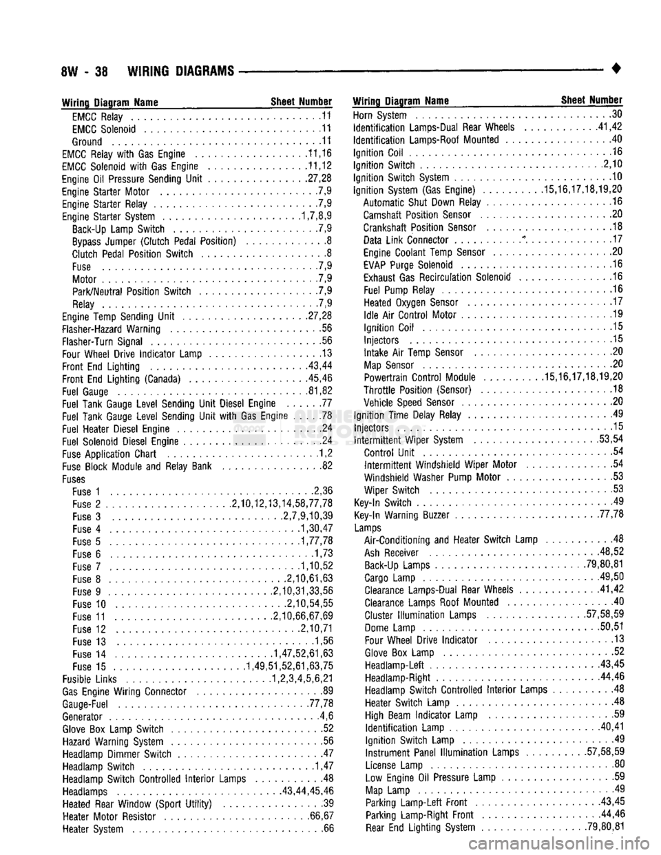
8W
- 38
WIRING
DIAGRAMS
• Wiring Diagram Name Sheet Number
EMCC
Relay
11
EMCC
Solenoid
11
Ground
11
EMCC
Relay
with Gas
Engine
11,16
EMCC
Solenoid
with Gas
Engine
11,12
Engine
Oil
Pressure Sending
Unit
.27,28
Engine
Starter
Motor
7,9
Engine
Starter
Relay
.7,9
Engine
Starter
System 1,7,8,9 Back-Up Lamp
Switch
.7,9
Bypass
Jumper
(Clutch
Pedal
Position)
8
Clutch
Pedal
Position
Switch
8
Fuse
. 7,9
Motor
7,9
Park/Neutral
Position
Switch
. .7,9
Relay
7,9
Engine Temp Sending
Unit
.
.27,28
Flasher-Hazard Warning
.56
Flasher-Turn Signal
56
Four Wheel
Drive
Indicator
Lamp
13
Front
End
Lighting
. .
.43,44
Front
End
Lighting
(Canada) 45,46
Fuel
Gauge
81,82
Fuel
Tank Gauge
Level
Sending
Unit
Diesel Engine
77
Fuel
Tank Gauge
Level
Sending
Unit
with Gas
Engine
78
Fuel
Heater
Diesel Engine
24
Fuel
Solenoid Diesel Engine
.24
Fuse
Application
Chart
1,2
Fuse
Block Module
and
Relay Bank
82
Fuses
Fuse
1 2,36
Fuse
2
.........
2,10,12,13,14,58,77,78
Fuse
3
2,7,9,10,39
Fuse
4
1,30,47
Fuse
5
1,77,78
Fuse
6
......
.1,73
Fuse
7
1,10,52
Fuse
8
.2,10,61,63
Fuse
9
.2,10,31,33,56
Fuse
10
.2,10,54,55
Fuse
11
2,10,66,67,69
Fuse
12
2,10,71
Fuse
13 1,56
Fuse
14
1,47,52,61,63
Fuse
15
1,49,51,52,61,63,75
Fusible Links 1,2,3,4,5,6,21
Gas
Engine
Wiring
Connector
89
Gauge-Fuel .77,78
Generator
.4,6
Glove
Box
Lamp
Switch
52
Hazard Warning System
. .56
Headlamp Dimmer
Switch
47
Headlamp
Switch
1,47
Headlamp
Switch
Controlled
Interior
Lamps
Headlamps 43,44,
Heated
Rear Window
(Sport
Utility)
Heater
Motor
Resistor
Heater
System Wiring Diagram Name Sheet Number
Horn System
30
Identification
Lamps-Dual Rear Wheels
41,42
Identification
Lamps-Roof Mounted
. 40
Ignition
Coil
.16
Ignition
Switch
.2,10
Ignition
Switch
System
10
Ignition
System (Gas Engine)
.........
.15,16,17,18,19,20
Automatic
Shut Down Relay
.16
Camshaft
Position
Sensor
20
Crankshaft
Position
Sensor
.18
Data
Link
Connector
* . . .17
Engine Coolant Temp
Sensor
20
EVAP
Purge Solenoid
16
Exhaust Gas
Recirculation
Solenoid
16
Fuel
Pump Relay
.16
Heated
Oxygen
Sensor
. . . 17
Idle
Air
Control
Motor
.19
Ignition
Coil
.15
Injectors
.15
Intake
Air
Temp
Sensor
. .20
Map
Sensor
. .20
Powertrain
Control
Module .15,16,17,18,19,20
Throttle
Position
(Sensor)
.18
Vehicle
Speed
Sensor
.20
Ignition
Time
Delay Relay
49
Injectors
.15 Intermittent
Wiper
System .53,54
Control
Unit
.54 Intermittent
Windshield
Wiper
Motor
54
Windshield
Washer Pump
Motor
53
Wiper
Switch
53
Key-In
Switch
49
Key-In Warning Buzzer 77,78
Lamps
Air-Conditioning
and
Heater
Switch
Lamp
48
Ash
Receiver .48,52 Back-Up Lamps
......
79,80,81
Cargo Lamp
.
.49,50 Clearance Lamps-Dual Rear Wheels .41,42
Clearance Lamps Roof Mounted
.40
Cluster
Illumination
Lamps
.
.57,58,59
Dome Lamp
50,51
Four Wheel
Drive
Indicator
.13
Glove
Box
Lamp
52
Headlamp-Left
43,45 Headlamp-Right 44,46
Headlamp
Switch
Controlled
Interior
Lamps
. 48
Heater
Switch
Lamp
.48
High Beam
Indicator
Lamp
.59
Identification
Lamp
.
.40,41
Ignition
Switch
Lamp
.49
Instrument
Panel
Illumination
Lamps
.
.57,58,59
License Lamp
. . . 80
.
.48 Low
Engine
Oil
Pressure Lamp
59
45,46
Map
Lamp
49
.
.39
Parking
Lamp-Left
Front
43,45
66,67 Parking Lamp-Right
Front
44,46 .
.66
Rear
End
Lighting
System .79,80,81
Page 514 of 1502
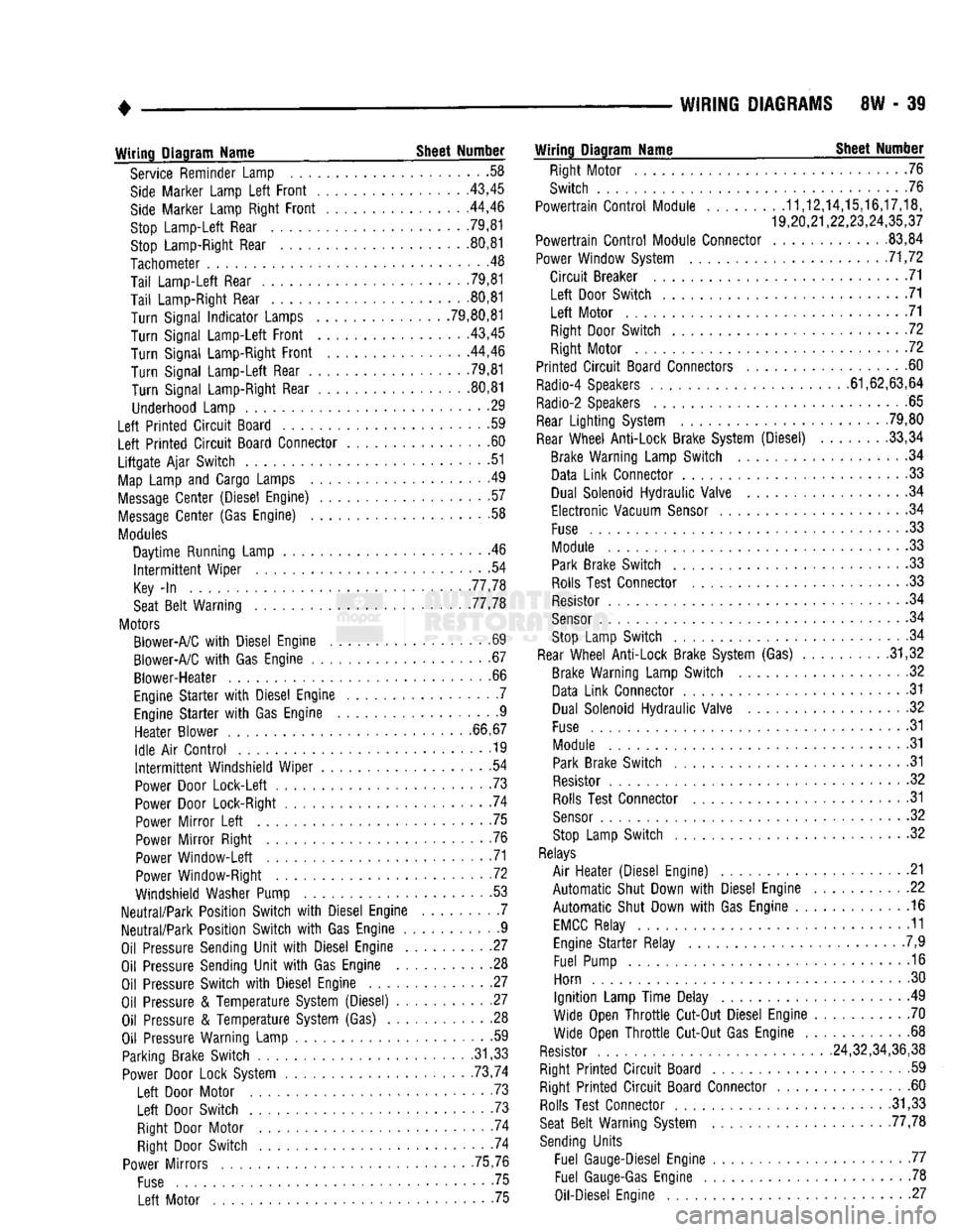
WIRING
DIAGRAMS
8W - 39
Wiring
Diagram
Name
Sheet
Number
Service Reminder Lamp .58
Side
Marker Lamp
Left
Front
43,45
Side
Marker Lamp Right
Front
. .44,46
Stop
Lamp-Left
Rear 79,81 Stop Lamp-Right Rear 80,81
Tachometer
.48
Tail
Lamp-Left
Rear .79,81
Tail
Lamp-Right Rear 80,81
Turn
Signal
Indicator
Lamps .79,80,81
Turn
Signal
Lamp-Left
Front
43,45
Turn
Signal Lamp-Right
Front
44,46
Turn
Signal
Lamp-Left
Rear .79,81
Turn
Signal Lamp-Right Rear 80,81
Underhood Lamp 29
Left
Printed
Circuit
Board .59
Left
Printed
Circuit
Board Connector 60
Liftgate
Ajar
Switch
51
Map
Lamp and Cargo Lamps .49
Message
Center
(Diesel Engine) 57
Message
Center
(Gas Engine) .58
Modules
Daytime
Running Lamp . .46
Intermittent
Wiper
.54
Key
-In
77,78
Seat
Belt
Warning 77,78
Motors Blower-A/C
with
Diesel Engine .69
Blower-A/C
with
Gas Engine 67
Blower-Heater
.66
Engine
Starter
with
Diesel Engine . .7 Engine
Starter
with
Gas Engine 9
Heater
Blower
66,67
Idle
Air
Control
............... ........
.19
Intermittent
Windshield
Wiper
54
Power Door
Lock-Left
.73
Power Door Lock-Right 74
Power
Mirror
Left
75
Power
Mirror
Right .76 Power
Window-Left
71
Power Window-Right .72
Windshield Washer Pump 53
Neutral/Park
Position
Switch
with
Diesel Engine 7
Neutral/Park
Position
Switch
with
Gas Engine 9
Oil Pressure Sending
Unit
with
Diesel Engine 27
Oil Pressure Sending
Unit
with
Gas Engine 28 Oil Pressure
Switch
with
Diesel Engine 27
Oil Pressure &
Temperature
System (Diesel) 27 Oil Pressure &
Temperature
System (Gas) . 28
Oil Pressure Warning Lamp • -59 Parking Brake
Switch
.31,33 Power Door Lock System . . 73,74
Left
Door Motor . .73
Left
Door
Switch
. 73
Right Door Motor . -74 Right Door
Switch
74
Power
Mirrors
75,76
Fuse
75
Left
Motor 75
Wiring
Diagram
Name
Sheet
Number
Right Motor 76
Switch
76
Powertrain
Control
Module
........
.11,12,14,15,16,17,18,
19,20,21,22,23,24,35,37
Powertrain
Control
Module Connector .83,84
Power Window System 71,72
Circuit
Breaker 71
Left
Door
Switch
71
Left
Motor 71 Right Door
Switch
72
Right Motor 72
Printed
Circuit
Board Connectors 60
Radio-4 Speakers 61,62,63,64
Radio-2 Speakers 65
Rear
Lighting
System 79,80
Rear
Wheel
Anti-Lock
Brake System (Diesel) 33,34 Brake Warning Lamp
Switch
.34 Data
Link
Connector 33
Dual Solenoid
Hydraulic
Valve 34
Electronic
Vacuum
Sensor
34
Fuse
.33 Module 33 Park Brake
Switch
33
Rolls Test Connector .33 Resistor .34
Sensor
. .34 Stop Lamp
Switch
. .34
Rear
Wheel
Anti-Lock
Brake System (Gas) . .31,32 Brake Warning Lamp
Switch
.32
Data
Link
Connector .31 Dual Solenoid
Hydraulic
Valve 32
Fuse
31
Module 31 Park Brake
Switch
31
Resistor 32 Rolls Test Connector 31
Sensor
32
Stop Lamp
Switch
32
Relays
Air
Heater
(Diesel Engine) .21
Automatic
Shut Down
with
Diesel Engine 22
Automatic
Shut Down
with
Gas Engine 16
EMCC
Relay 11 Engine
Starter
Relay .7,9
Fuel Pump 16
Horn 30
Ignition
Lamp
Time
Delay 49
Wide Open
Throttle
Cut-Out Diesel Engine 70
Wide Open
Throttle
Cut-Out Gas Engine 68
Resistor 24,32,34,36,38
Right
Printed
Circuit
Board 59 Right
Printed
Circuit
Board Connector 60 Rolls Test Connector .31,33
Seat
Belt
Warning System 77,78
Sending
Units
Fuel Gauge-Diesel Engine 77 Fuel
Gauge-Gas
Engine 78
Oil-Diesel Engine 27
Page 515 of 1502
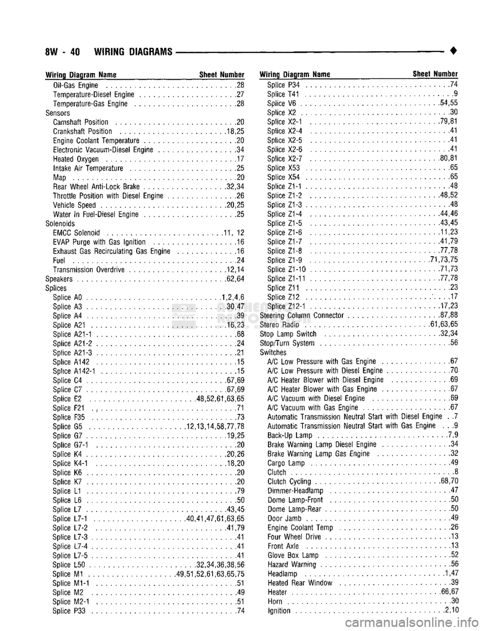
8W
- 40
WIRING DIAGRAMS
Wiring Diagram Name Sheet Number
Oil-Gas
Engine
28
Temperature-Diesel Engine
. . . ., 27
Temperature-Gas Engine
. .28
Sensors
Camshaft Position
. . .20
Crankshaft Position
. .
.18,25
Engine
Coolant
Temperature
20
Electronic
Vacuum-Diesel Engine
. .34
Heated Oxygen
17
Intake
Air
Temperature
25
Map
20
Rear
Wheel Anti-Lock Brake 32,34
Throttle
Position
with
Diesel Engine
26
Vehicle Speed .20,25 Water
In
Fuel-Diesel Engine
25
Solenoids
EMCC
Solenoid
11, 12
EVAP
Purge
with
Gas
Ignition
.16
Exhaust
Gas
Recirculating
Gas Engine
.16
Fuel
.24
Transmission Overdrive
12,14
Speakers
62,64
Splices
Splice AO 1,2,4,6
Splice
A3
30,47
Splice
A4 39
Splice A21
16,23
Splice A21-1
. .68
Splice
A21-2 24
Splice A21-3
21
Splice A142
.15
Splice
A142-1 15
Splice
C4
.67,69
Splice
C7
.67,69
Splice
E2
.48,52,61,63,65
Splice F21
. , 71
Splice
F35 73
Splice
G5
12,13,14,58,77,78 Splice
G7
........... .19,25
Splice G7-1
. . .20
Splice
K4
20,26 Splice K4-1
.... ..... ; . 18,20
Splice
K6 , 20
Splice
K7 .20
Splice
L1 .79
Splice
L6 . .50
Splice
L7
43,45
Splice L7-1 40,41,47,61,63,65
Splice
L7-2
.41,79
Splice
L7-3 .41
Splice
L7-4 41
Splice
L7-5 .41
Splice
L50
......
.
........... .32,34,36,38,56
Splice
M1
49,51,52,61,63,65,75 Splice M1-1
51
Splice
M2 . .49
Splice M2-1
.51
Splice
P33 . 74
Wiring Diagram Name Sheet Number
Splice
P34 .... .74
Splice T41 ..............
.9
Splice
V6 . .
.54,55
Splice
X2 . .30
Splice X2-1
. . . .
.79,81
Splice X2-4
41
Splice X2-5
.41
Splice X2-6
.... .41
Splice X2-7
80,81
Splice X53
.65
Splice
X54
..........
. . 65
Splice Z1-1
.48
Splice Z1-2 48,52
Splice Z1-3
. . 48
Splice Z1-4
...
.44,46
Splice
Z1-5 ..... . . . .
-43,45
Splice Z1-6
11,23
Splice
Z1-7 .
.41,79
Splice Z1-8 77,78 Splice Z1-9
. .
............ .71,73,75
Splice Z1-10
. 71,73
Splice Z1-11 .77,78
Splice Z11
23
Splice
Z12 ' 17
Splice Z12-1
17,23
Steering Column Connector
.
87,88
Stereo Radio 61,63,65
Stop
Lamp Switch 32,34
Stop/Turn System
.56
Switches
A/C
Low
Pressure
with
Gas Engine
67
A/C
Low
Pressure
with
Diesel Engine
70
A/C
Heater Blower
with
Diesel Engine
69
A/C
Heater Blower
with
Gas Engine
67
A/C
Vacuum
with
Diesel Engine
69
A/C
Vacuum
with
Gas Engine
67
Automatic
Transmission
Neutral
Start
with
Diesel Engine
. .7
Automatic
Transmission
Neutral
Start
with
Gas Engine
. . .9
Back-Up
Lamp
.7,9
Brake Warning Lamp Diesel Engine
34
Brake Warning Lamp Gas Engine
. .32
Cargo
Lamp
49
Clutch
8
Clutch
Cycling
...
.68,70 Dimmer-Headlamp
47
Dome
Lamp-Front
. .50
Dome
Lamp-Rear
50
Door
Jamb
. 49
Engine
Coolant Temp
.26
Four
Wheel Drive
13
Front
Axle
13
Glove
Box
Lamp
. .52
Hazard Warning
.56
Headlamp
1,47
Heated Rear Window
39
Heater
. .
.66,67
Horn
.30
Ignition
2,10
Page 575 of 1502
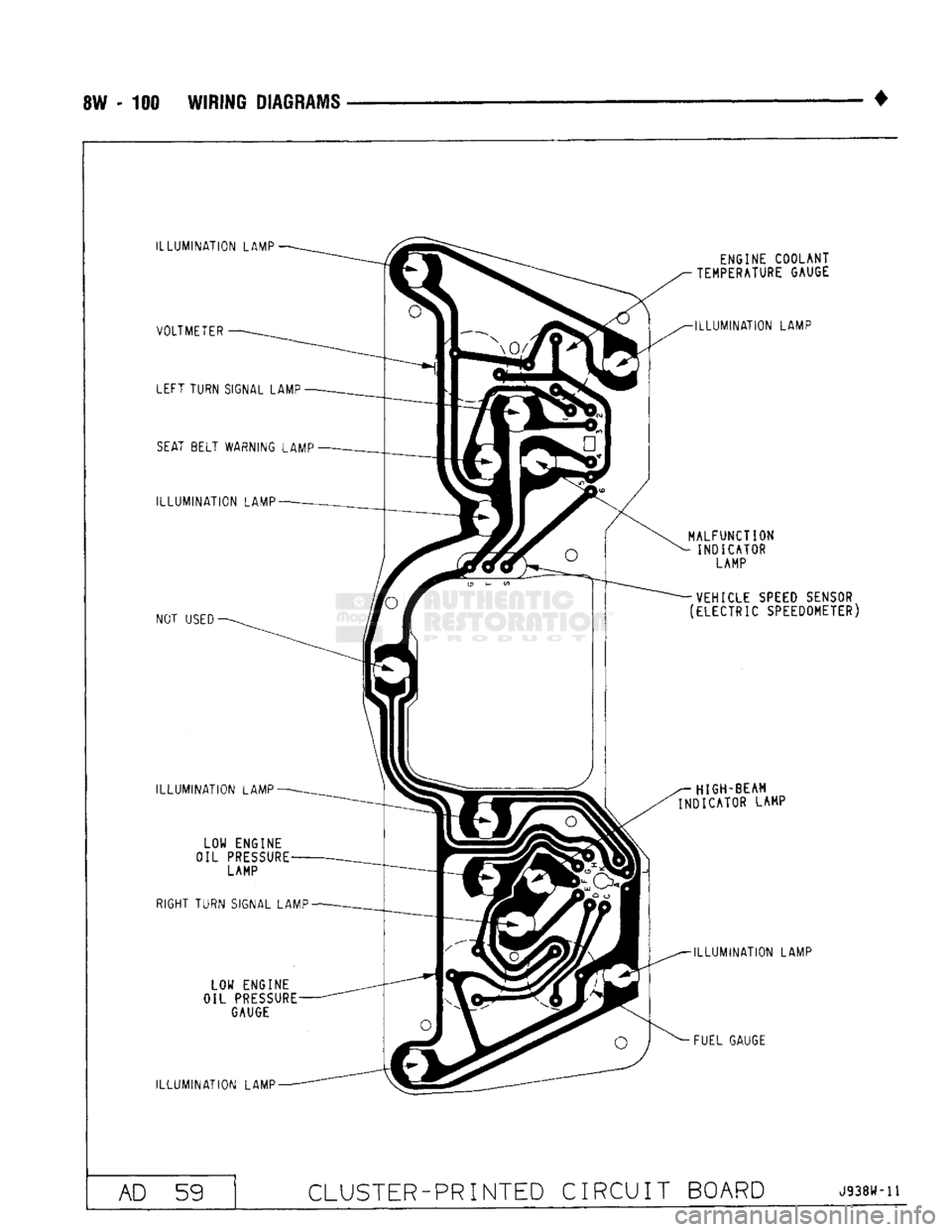
8W - 100 WIRING DIAGRAMS
ILLUMINATION
LAMP VOLTMETER LEFT TURN SIGNAL LAMP
SEAT
BELT WARNING LAMP
ILLUMINATION
LAMP
NOT
USED
ILLUMINATION
LAMP LOW ENGINE
OIL
PRESSURE
LAMP
RIGHT TURN SIGNAL LAMP
LOW ENGINE
OIL
PRESSURE
GAUGE
ILLUMINATION
LAMP ENGINE COOLANT
TEMPERATURE GAUGE
ILLUMINATION
LAMP
MALFUNCTION
INDICATOR LAMP
VEHICLE SPEED SENSOR
(ELECTRIC SPEEDOMETER)
HIGH-BEAM
INDICATOR LAMP
ILLUMINATION
LAMP
FUEL GAUGE AD 59
CLUSTER-PRINTED
CIRCUIT BOARD
J938W-11