1993 DODGE TRUCK brake
[x] Cancel search: brakePage 74 of 1502
•
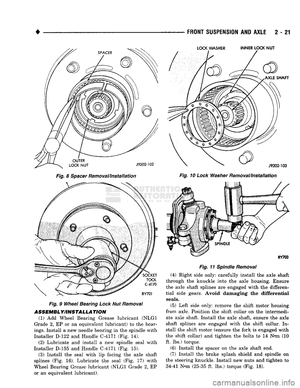
Fig.
8
Spacer
Removal/Installation
Fig.
9
Wheel
Bearing
Lock
Nut
Removal
ASSEMBL
Y/INSTALLA
TION
(1) Add Wheel Bearing Grease lubricant (NLGI
Grade 2, EP or an equivalent lubricant) to the bear
ings.
Install a new needle bearing in the spindle with
Installer D-122 and Handle C-4171 (Fig. 14).
(2) Lubricate and install a new spindle seal with
Installer D-155 and Handle C-4171 (Fig. 15).
(3) Install the seal with lip facing the axle shaft
splines (Fig. 16). Lubricate the seal (Fig. 17) with
Wheel Bearing Grease lubricant (NLGI Grade 2, EP or an equivalent lubricant).
FRONT
SUSPENSION
AND
AXLE
2 - 21
LOCK
WASHER INNER LOCK
NUT
Fig.
10
Lock
Washer
Removal/Installation
Fig.
11
Spindle
Removal
(4) Right side only: carefully install the axle shaft
through the knuckle into the axle housing. Ensure
the axle shaft splines are engaged with the differen
tial side gears. Avoid damaging the differential
seals.
(5) Left side only: remove the shift motor housing
from axle. Position the shift collar on the intermedi ate axle shaft. Install the axle shaft, ensure the axle
shaft splines are engaged with the shift collar. In stall the shift motor (ensure the fork is engaged with
the shift collar) and tighten the bolts to 14 Nnn (10
ft. lbs.) torque.
(6) Install the spacer on the axle shaft end.
(7) Install the brake splash shield and spindle on
the steering knuckle. Install new nuts and tighten to 34-41 Nnn (25-35 ft. lbs.) torque (Fig. 18).
Page 75 of 1502
2
- 22
FRONT SUSPENSION
AND
AXLE
——
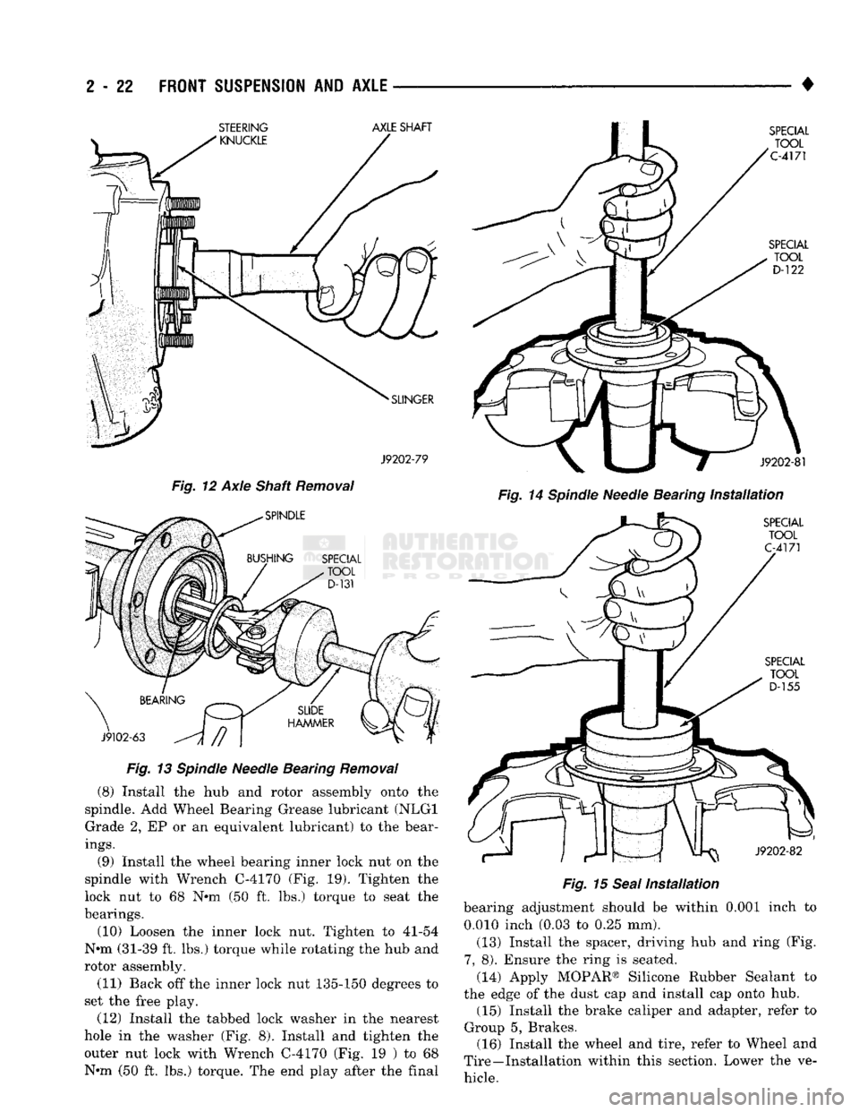
J9202-79
Fig. 12 Axle Shaft Removal
Fig. 13 Spindle Needle Bearing Removal (8) Install the hub and rotor assembly onto the
spindle. Add Wheel Bearing Grease lubricant (NLGI Grade 2, EP or an equivalent lubricant) to the bear
ings.
(9) Install the wheel bearing inner lock nut on the
spindle with Wrench C-4170 (Fig. 19). Tighten the
lock nut to 68 N*m (50 ft. lbs.) torque to seat the
bearings.
(10) Loosen the inner lock nut. Tighten to 41-54
N*m (31-39 ft. lbs.) torque while rotating the hub and
rotor assembly.
(11) Back off the inner lock nut 135-150 degrees to
set the free play.
(12) Install the tabbed lock washer in the nearest
hole in the washer (Fig. 8). Install and tighten the outer nut lock with Wrench C-4170 (Fig. 19 ) to 68
N«m (50 ft. lbs.) torque. The end play after the final •
Fig. 14 Spindle Needle Bearing Installation Fig. 15 Seal Installation bearing adjustment should be within 0.001 inch to
0.010 inch (0.03 to 0.25 mm).
(13) Install the spacer, driving hub and ring (Fig.
7,
8). Ensure the ring is seated.
(14) Apply MOPAR® Silicone Rubber Sealant to
the edge of the dust cap and install cap onto hub. (15) Install the brake caliper and adapter, refer to
Group 5, Brakes. (16) Install the wheel and tire, refer to Wheel and
Tire—Installation within this section. Lower the ve hicle. STEERING
AXLE
SHAFT
Page 81 of 1502
2 - 28
FRONT
SUSPENSION
AND
AXLE
DISCONNECT
AXLE/SHIFT
MOTOR
DIAGNOSIS
TWO-WHEEL DRIVE
OPERATION
DIAGNOSIS
FOUR-WHEEL DRIVE
INDICATOR
LIGHT
WILL NOT GO OUT WHEN
TRANSFER CASE SELECTOR
IS
MOVED FROM 4H TO 2H POSITION.
RAISE
VEHICLE SO ALL FOUR WHEELS ARE
FREE
TO ROTATE. INSPECT INDICATOR
SWITCH AND WIRING ON SHIFT MOTOR HOUSING FOR DAMAGE AND SHORT-CIRCUIT.
REPAIR
AS NECESSARY.
YES
i
START ENGINE DEPRESS BRAKE
PEDAL.
PLACE TRANSFER
CASE
SELECTOR IN 2H POSITION AND TRANSMISSION IN
DRIVE
(AUTOMATIC)
OR FIRST
GEAR
(MANUAL). EASE OFF FROM
BRAKE
AND LET WHEELS ROTATE SLOWLY. TEST COMPLETE
FRONT DRIVE SHAFT DOES
NOT ROTATE. FRONT DRIVE
SHAFT ROTATES.
FOUR-WHEEL DRIVE INDICATOR
LIGHT
REMAINS
ON. INSPECT TRANSFER
CASE
LINKAGE.
PLACE
TRANSMISSION IN NEUTRAL. TEST FOR VACUUM
IN VACUUM HOSE
THAT
CONNECTS TO INBOARD SHIFT MOTOR PORT.
(VACUUM SHOULD BE
BETWEEN 10-20 IN. HG.)
CHECK
TRANSFER
CASE.
REPAIR
AS
NECESSARY.
NO VACUUM
OR LOW VACUUM. VACUUM OK
INSPECT INTAKE MANIFOLD
VACUUM SUPPLY HOSE CONNECTION,
TRANSFER CASE VACUUM SWITCH
CONNECTION, VACUUM RESERVOIR, AND SHIFT SYSTEM VACUUM HOSES
FOR PROPER CONNECTION, RESTRICTION,
AIR LEAKS, AND DAMAGE. REPAIR OR REPLACE
AS
NECESSARY. STOP ENGINE
—r~
FRONT AXLE
DISCONNECTS.
INSPECT VACUUM
HOSES
FOR AIR LEAKS, KINKS, ETC.
REPAIR
AS NECESSARY. FRONT AXLE
DOES
NOT
DISCONNECT.
REMOVE SHIFT MOTOR
HOUSING COVER. CONNECT VACUUM PUMP TO
SHIFT MOTOR PORT.
REPLACE
SHIFT MOTOR
IF ARMATURE DOES
NOT MOVE IN AND OUT FREELY. FRONT AXLE
WILL NOT DISCONNECT.
J9002-95
REMOVE SHIFT MOTOR HOUSING
COVER. INSPECT SHIFT FORK, COLLAR, AND AXLE SHAFTS.
REPAIR
OR REPLACE AS
NECESSARY
Page 82 of 1502
FRONT
SUSPENSION AND
AXLE
2 - 29
DISCONNECT AXLE/SHIFT MOTOR DIAGNOSIS
(CONT'D)
FOUR-WHEEL
DRIVE
OPERATION
DIAGNOSIS
FOUR-WHEEL DRIVE INDICATOR
LIGHT
DOES NOT
LIGHT
WHEN TRANSFER CASE SELECTOR IN 4H OR 4L POSITION.
RAISE
VEHICLE SO ALL FOUR
WHEELS ARE FREE TO ROTATE.
START ENGINE, DEPRESS BRAKE PEDAL.
PLACE
TRANSFER CASE SELECTOR IN 4H
POSITION AND TRANSMISSION LEVER IN DRIVE
(AUTOMATIC)
OR IN FIRST GEAR
(MANUAL) TO CONFIRM TRANSFER CASE ENGAGEMENT IN 4H. LET WHEELS ROTATE SLOWLY.
FRONT DRIVE SHAFT DOES
NOT ROTATE. FRONT DRIVE
SHAFT TURNS.
INSPECT TRANSFER
CASE
LINKAGE.
CHECK
TRANSFER
CASE.
REPAIR AS
NECESSARY.
FRONT AXLE
CONNECTS.
FOUR-WHEEL DRIVE INDICATOR
LIGHT
DOES
NOT LIGHT.
INSPECT FWD INDICATOR SWITCH, WIRING, AND
LAMP FOR DAMAGE.
REPAIR
AS NECESSARY. RECOMMENDATION:
CHECK
VACUUM SHIFT SYSTEM FOR PROPER
OPERATION.
PLACE
TRANSMISSION
LEVER IN NEUTRAL POSITION. FRONT AXLE
DOES
NOT
CONNECT.
REMOVE VACUUM HOSES FROM AXLE SHIFT MOTOR PORTS.
START ENGINE. TEST FOR VACUUM AT HOSE REMOVED FROM
OUT
BOARD
PORT ON SHIFT MOTOR,
SHOULD BE BETWEEN 10-20 IN HG.
NO VACUUM
OR LOW VACUUM. STOP ENGINE
H VACUUM OK
INSPECT INTAKE MANIFOLD
VACUUM SUPPLY HOSE CONNECTION, TRANSFER CASE VACUUM SWITCH
CONNECTION, VACUUM RESERVOIR, AND SHIFT
SYSTEM VACUUM HOSES FOR PROPER CONNECTION, RESTRICTION, LEAKS, AND DAMAGE.
REPAIR
OR REPLACE AS NECESSARY. CONNECT A VACUUM PUMP
TO THE OUTBOARD
SHIFT MOTOR PORT.
APPLY 15 INCHES HG. VACUUM AND ROTATE LEFT WHEEL.
NO VACUUM FRONT AXLE
CONNECTED.
CHECK
TRANSFER CASE
VACUUM SWITCH. REPLACE OR REPAIR IF SWITCH
PLUNGER IS DIFFICULT TO MOVE OR BINDS. FRONT AXLE
DOES
NOT
CONNECT.
INSPECT VACUUM HOSES FOR LEAKS, KINKS, ETC.
REPAIR
AS NECESSARY. REMOVE SHIFT MOTOR
HOUSING COVER. CONNECT VACUUM PUMP TO
SHIFT MOTOR PORT.
REPLACE
SHIFT MOTOR
IF ARMATURE DOES
NOT MOVE IN AND OUT FREELY. REMOVE SHIFT MOTOR HOUSING
COVER. INSPECT SHIFT FORK, COLLAR, AND AXLE SHAFTS.
REPAIR
OR REPLACE AS
NECESSARY.
*
REMOVE SHIFT MOTOR HOUSING
COVER. INSPECT SHIFT FORK, COLLAR, AND AXLE SHAFTS.
REPAIR
OR REPLACE AS
NECESSARY.
FRONT AXLE
WILL NOT CONNECT.
REMOVE SHIFT MOTOR HOUSING
COVER. INSPECT SHIFT FORK, COLLAR, AND AXLE SHAFTS.
REPAIR
OR REPLACE AS
NECESSARY.
FRONT AXLE
WILL NOT CONNECT.
REMOVE SHIFT MOTOR HOUSING
COVER. INSPECT SHIFT FORK, COLLAR, AND AXLE SHAFTS.
REPAIR
OR REPLACE AS
NECESSARY.
J9002-96
Page 85 of 1502
2
- 32
FRONT
SUSPENSION
AND
AXLE
• (5) Disconnect flexible brake fluid hose fittings at
the frame crossmember. Plug the hoses at the fit
tings.
(6) Remove the shock absorber lower nut and stud
from the axle shaft tube bracket. Remove the nuts and disconnect the stabilizer bar links from the
spring brackets.
(7) Disconnect the vacuum hoses and wiring con
nections from the shift motor housing.
(8) Remove nuts and the washers from the spring
U-bolts. Remove the complete front axle from the ve
hicle.
INSTALLATION
(1) Position the front axle under the front of the
vehicle with the axle spring pads under the springs.
Place the spring brackets over the springs. Make sure the stabilizer bar link bolt holes face toward the
rear of the vehicle.
(2) Install the spring U-bolts, washers and nuts.
Refer to Front Suspension — 4WD Vehicles within
this group. (3) Install the shock absorber. Refer to Front Sus
pension — 4WD Vehicles within this group. (4) Connect the stabilizer bar links to the spring
brackets. Refer to Front Suspension-4WD Vehicles
within this group.
(5) Remove plugs and connect the brake hose fit
tings.
Refer to Group 5, Brakes. (6) Connect the drag-link ball stud to the steering
knuckle arm. Refer to Group 19, Steering. (7) Connect the drive shaft to the pinion yoke with
the installation reference marks aligned. Install the
washers and the nuts and tighten to 19 N*m (14 ft. lbs.) torque.
(8) Connect the vacuum hoses and wiring connec
tions to the shift motor housing. (9) Remove the supports, lower the vehicle and re
move the block from the brake pedal.
(10) Raise the vehicle.
• Bleed and adjust the brakes
• Lubricate all the ball stud fittings
• Inspect the differential housing lubricant level. Re
fer to Group 0, Lubrication and Maintenance. (11) Lower the vehicle and test the axle and sus
pension operation.
DIFFERENTIAL
DISASSEMBLY
REMOVAL/DISASSEMBLY (1) Note the installation reference letters
stamped on the bearing caps and housing ma
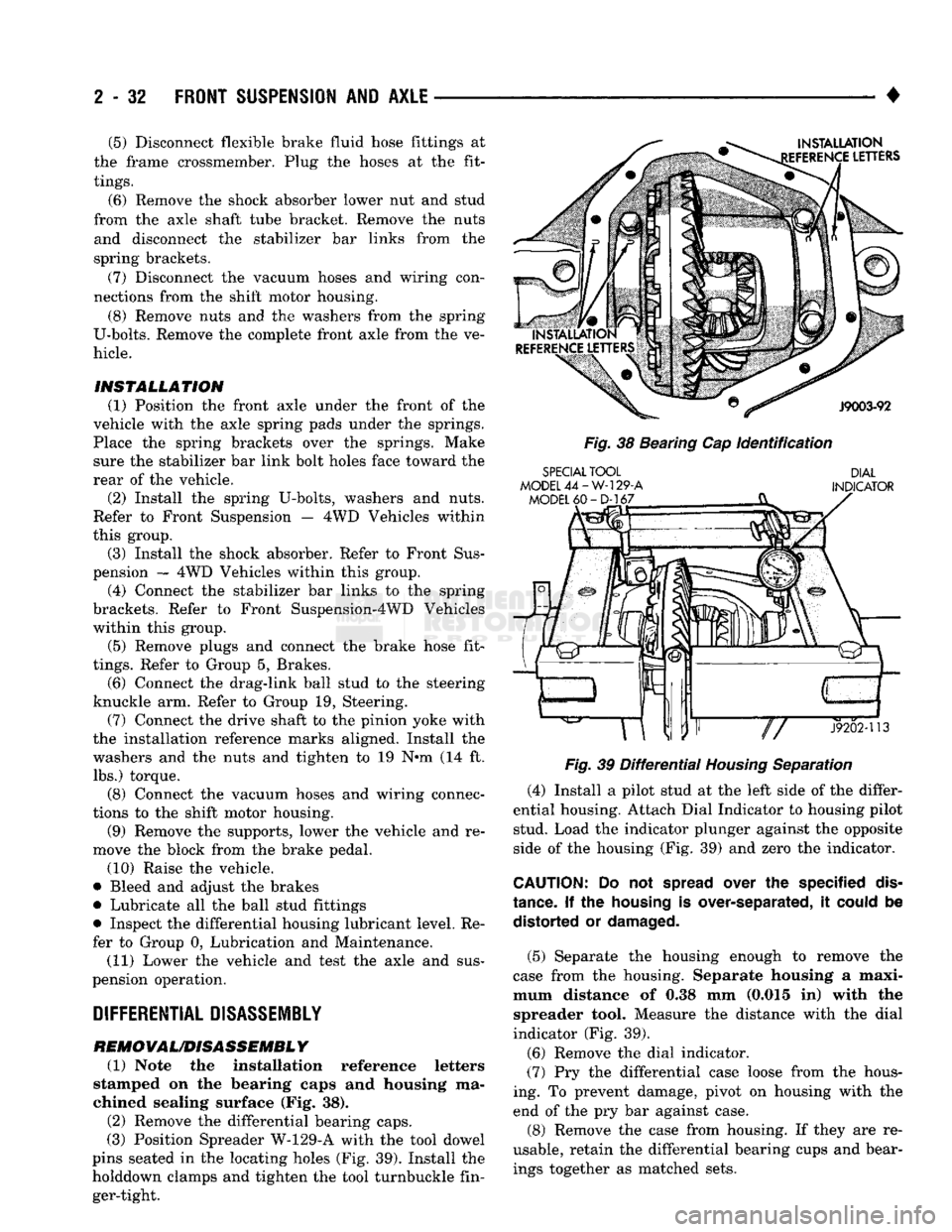
chined sealing surface (Fig. 38). (2) Remove the differential bearing caps.
(3) Position Spreader W-129-A with the tool dowel
pins seated in the locating holes (Fig. 39). Install the
holddown clamps and tighten the tool turnbuckle fin ger-tight.
INSTALLATION
EFERENCE
LETTERS
J9003-92
Fig.
38 Bearing Cap
Identification
SPECIAL
TOOL
MODEL
44-W-129-A
MODEL
60-D-167
DIAL
INDICATOR
«ar"P—
J9202-113
Fig.
39
Differential
Housing
Separation
(4) Install a pilot stud at the left side of the differ
ential housing. Attach Dial Indicator to housing pilot stud. Load the indicator plunger against the opposite
side of the housing (Fig. 39) and zero the indicator.
CAUTION:
Do not
spread
over the specified
dis
tance.
If the
housing
is over-separated, it
could
be distorted or
damaged.
(5) Separate the housing enough to remove the
case from the housing. Separate housing a maxi
mum distance of 0.38 mm (0.015 in) with the spreader tool. Measure the distance with the dial
indicator (Fig. 39).
(6) Remove the dial indicator.
(7) Pry the differential case loose from the hous
ing. To prevent damage, pivot on housing with the end of the pry bar against case.
(8) Remove the case from housing. If they are re
usable, retain the differential bearing cups and bear ings together as matched sets.
Page 105 of 1502
2
- 52
FRONT
SUSPENSION
AND
AXLE
•
PINION
SEAL
J9203-55
Fig. 4 Seal Removal
SPECIAL TOOL
G4735
J9203-56
Fig. 5 Pinion Seal Installation the differential housing, if necessary.
(6)
Lower the vehicle.
LOCKING HUBS, SPINDLE AND AXLE SHAFT
REM0VAL/D1SASSEMBL
Y
(1) Raise and support the front of vehicle. (2) Remove the wheel/tire.
(3) Remove the brake caliper, refer to Group 5,
Brakes. Support the caliper to the frame structure
with wire. DIFFERENTIAL
Fig. 6 Tightening Pinion Shaft Nut
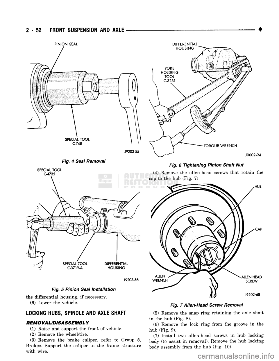
(4) Remove the allen-head screws that retain the
cap to the hub (Fig. 7).
Fig. 7 Allen-Head Screw Removal (5) Remove the snap ring retaining the axle shaft
in the hub (Fig. 8).
(6)
Remove the lock ring from the groove in the
hub (Fig. 9).
(7) Install two allen-head screws in hub locking
body (to assist in removal). Remove the hub locking
body assembly from the hub (Fig. 10).
Page 107 of 1502
2
- 54
FRONT SUSPENSION
AND
AXLE
Fig.
12 Spindle Removal
SEAL
J9202-73
Fig.
13 Axle Shaft Removal
Fig.
14
Spindle
Needle Bearing
Removal
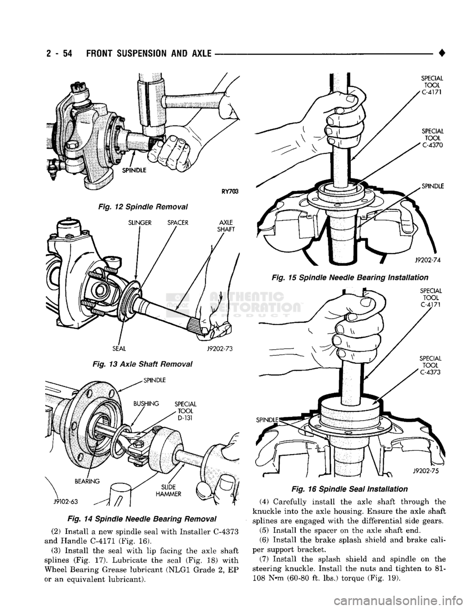
(2) Install a new spindle seal with Installer C-4373
and Handle C-4171 (Fig. 16).
(3) Install the seal with lip facing the axle shaft
splines (Fig. 17). Lubricate the seal (Fig. 18) with
Wheel Bearing Grease lubricant (NLGI Grade 2, EP
or an equivalent lubricant). •
Fig.
15
Spindle
Needle Bearing
Installation
Fig.
16
Spindle
Seal
Installation
(4) Carefully install the axle shaft through the
knuckle into the axle housing. Ensure the axle shaft splines are engaged with the differential side gears.
(5) Install the spacer on the axle shaft end.
(6) Install the brake splash shield and brake cali
per support bracket.
(7) Install the splash shield and spindle on the
steering knuckle. Install the nuts and tighten to 81- 108 N-m (60-80 ft. lbs.) torque (Fig. 19).
Page 108 of 1502
•
Fig.
17 Axle Shaft
Seal
Installation
Fig.
19
Spindle
Installation
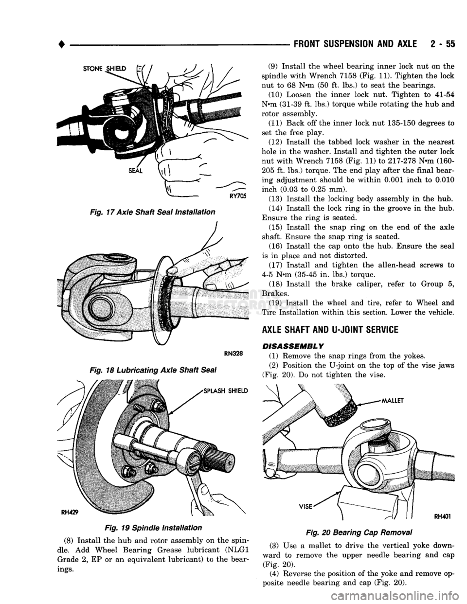
(8) Install the hub and rotor assembly on the spin
dle.
Add Wheel Bearing Grease lubricant (NLGI Grade 2, EP or an equivalent lubricant) to the bear
ings.
FRONT
SUSPENSION
AND
AXLE
2 - 51
Fig.
20 Bearing Cap
Removal
(3) Use a mallet to drive the vertical yoke down
ward to remove the upper needle bearing and cap (Fig. 20).
(4) Reverse the position of the yoke and remove op
posite needle bearing and cap (Fig. 20). (9) Install the wheel bearing inner lock nut on the
spindle with Wrench 7158 (Fig. 11). Tighten the lock
nut to 68 N*m (50 ft. lbs.) to seat the bearings. (10) Loosen the inner lock nut. Tighten to 41-54
N*m (31-39 ft. lbs.) torque while rotating the hub and
rotor assembly.
(11) Back off the inner lock nut 135-150 degrees to
set the free play.
(12) Install the tabbed lock washer in the nearest
hole in the washer. Install and tighten the outer lock nut with Wrench 7158 (Fig. 11) to 217-278 N-m (160-205 ft. lbs.) torque. The end play after the final bear
ing adjustment should be within 0.001 inch to 0.010 inch (0.03 to 0.25 mm).
(13) Install the locking body assembly in the hub.
(14) Install the lock ring in the groove in the hub.
Ensure the ring is seated. (15) Install the snap ring on the end of the axle
shaft. Ensure the snap ring is seated.
(16) Install the cap onto the hub. Ensure the seal
is in place and not distorted.
(17) Install and tighten the allen-head screws to
4-5 N-m (35-45 in. lbs.) torque.
(18) Install the brake caliper, refer to Group 5,
Brakes. (19) Install the wheel and tire, refer to Wheel and
Tire Installation within this section. Lower the vehicle.
AXLE SHAFT AND
U-JOINT
SERVICE DISASSEMBLY
(1) Remove the snap rings from the yokes.
(2) Position the U-joint on the top of the vise jaws
(Fig. 20). Do not tighten the vise.