1993 DODGE TRUCK check engine
[x] Cancel search: check enginePage 1468 of 1502
•
HEATING AND AIR CONDITIONING 24 - 31
SOLID
LINE
INDICATES ENGINE
VACUUM
„
VIOLET
CHECK
VALVE f
SOLID
LINE INDICATES
ENGINE
VACUUM
VIOLET
YELLOW
I ACTUATOR ^OUTSIDE
AIR
OFF, MAX A/C
A/C,
VENT
SOLID
LINE
INDICATES
ENGINE
VACUUM VIOLET
RED
/ I
CHECK
VALVE I • DEFROSTER-*-*-
H5WN
RESTRICTOR
DARK
GREEN
AIR/COND.
t
ACTUATOR
I
HEATING
WATER VALVE
ACTUATOR ^
| •
ON
-*-^OFF
YELLOW
HEAT
ACTUATOR
LIGHT
GREEN
RECIRCULATING
GRAY ACTUATOR
OUTSIDE
AIR
SOLID
LINE INDICATES
ENGINE
VACUUM VIOLET
ACTUATOR HEAT
* PUSH BUTTON CONTROL
VACUUM SWITCH
** RESTRICTOR IS PART OF VACUUM CONNECTOR AND NOT VISIBLE ACTUATOR
OUTSIDE
RN1001
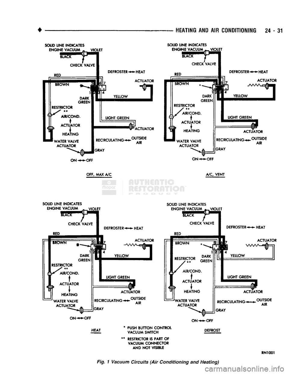
Fig. 1
Vacuum
Circuits
(Air
Conditioning
and
Heating)
Page 1474 of 1502
•
Fig.
12
Blower
Wheel
(7) Install the 3 arms. Install nut that attaches 3
door arms to doors on the top cover of the unit (Fig.
11).
INSTALLATION
(1) Install the evaporator heater assembly. Plastic
instrument panel may have to be flexed outward.
(2) Install and tighten the screw that retains the
evaporator heater assembly to cowl side sheet metal.
(3) Install the retaining nuts on engine side.
(4) Connect vacuum lines on engine side.
(5) Install blower motor connector on engine side.
(6) Remove wiring connector from resistor block.
(7) Connect vacuum lines from extension on con
trol unit and attach vacuum lines to defroster duct (Fig. 10).
(8) Connect temperature control cable to unit
through glove box. (9) Install floor air distribution duct.
(10) Install center distribution duct.
(11) Attach radio ground strap. (12) Remove right half of lower reinforcement by
removing screws attaching it to the instrument panel and the screw attaching it to the cowl side trim
panel. (13) Install ash receiver.
(14) Install structural brace through glove box
opening. Install screws and loosen nuts. (15) Install glove box by installing mounting
screws. (16) Install right cowl side trim panel, if so
equipped. (17) Position transfer case and/or gear shift levers.
(18) Remove plugs from heater hoses and unit. In
stall condensate tube (Fig. 9). (19) Connect refrigerant and heater lines to unit
on engine side.
} (20) Connect the negative cable to the battery. (21) Fill the cooling system (refer to Group 7, Cool
ing System). (22) Evacuate and charge the system.
(23) Check operation of all controls and perfor
mance of the A/C system.
HEATING
AND AIR
CONDITIONING
24 - 37
'H"
VALVE
Fig.
13
Expansion
(H)
Valve
Assembly
ELECTRONIC
TEMPERATURE
CYCLING
SWITCH
REMOVAL
(1) Remove the electrical wires to the switch.
(2) Rotate switch counterclockwise to remove from
pressure switch port. (3) Remove and discard old O-ring.
INSTALLATION
(1) Install new O-ring. Refrigerant oil must be ap
plied to the new O-ring.
(2) Rotate switch clockwise to install on suction
line pressure switch port. Tighten switch to 5.65 N#m (50 in. lbs.) torque.
CAUTION:
Power
tools
should
not be
used
for in
stallation
of the switch. The
possibility
of stripping
the
switch
threads
occurs
above
5.88 N*m (52 in.
lbs.)
torque.
(3) Connect wires. (4) Verify operation.
EXPANSION
(H)
VALVE
REMOVAL
The system must be completely discharged before
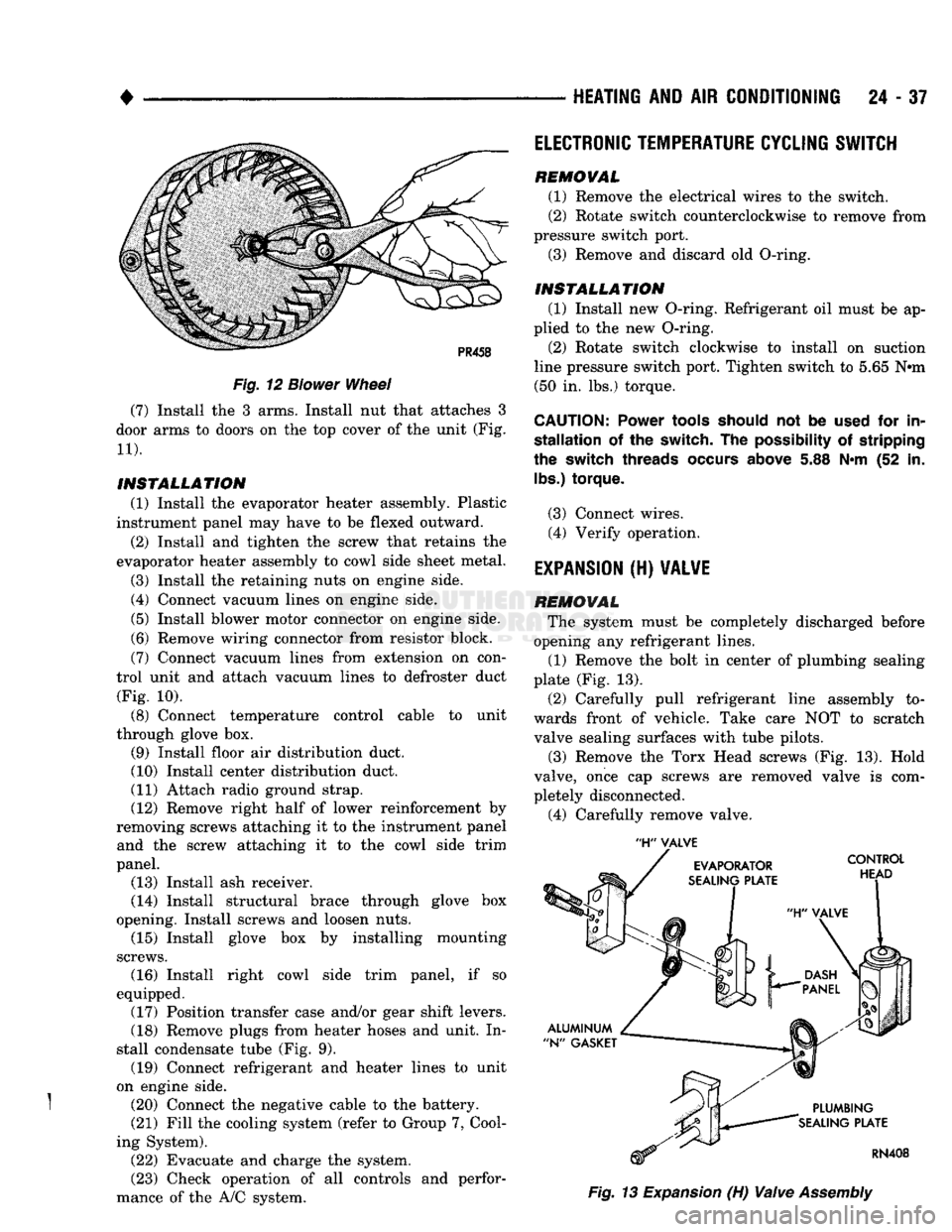
opening any refrigerant lines. (1) Remove the bolt in center of plumbing sealing
plate (Fig. 13).
(2) Carefully pull refrigerant line assembly to
wards front of vehicle. Take care NOT to scratch valve sealing surfaces with tube pilots.
(3) Remove the Torx Head screws (Fig. 13). Hold
valve, once cap screws are removed valve is com
pletely disconnected.
(4) Carefully remove valve.
Page 1478 of 1502
•
EMISSION
CONTROL
SYSTEMS
25
- 1
CONTENTS
page page
AIR INJECTION
SYSTEM-o
9L
HDC-GAS EVAPORATIVE EMISSION CONTROLS
6
ENGINE
15
EXHAUST EMISSION CONTROLS
10
COMPONENT
REMOVAL/INSTALLATION
17
GENERAL INFORMATION
1
GENERAL
INFORMATION
Throughout this group, references are made
to
par
ticular vehicle models
by
alphabetical designation
or
by the particular vehicle nameplate.
A
chart showing a breakdown
of
alphabetical designations
is
included
in
the
Introduction section
at
the
beginning
of
this
manual.
The 5.9L (V-8) gas powered engine will
be
referred
to
in
this group
as
either the: LDC (Light Duty Cy cle)
or
HDC (Heavy Duty Cycle) engine.
The
HDC
engine can
be
easily identified
by
the
use
of
an en
gine mounted
air
injection pump. The 3.9L/5.2L/5.9L
LDC engine will not use
an
air
injection pump.
Maintenance requirements for LDC and HDC emis
sion systems differ because
of
different load
and
op
erating conditions. This section will cover emission control systems
for
the 3.9L (V-6), 5.2L (V-8), 5.9L LDC (V-8), 5.9L HDC (V-8) and 5.9L (in-line six cylinder) diesel engines.
SERVICE
REMINDER INDICATOR
(SRI)
LIGHT
The instrument panel mounted SRI light was for
merly referred
to as the
emission maintenance
re
minder (EMR) light.
It is
used with 5.9L HDC-gas
powered engines only.
It is
not
used with diesel
en
gines.
The SRI system
is
incorporated into the powertrain
control module (PCM)
(the
PCM
was
formerly
re
ferred
to as the
engine controller
or
SBEC).
The
PCM records
the
vehicles mileage and stores
it
into
memory every
8
miles. At that time, the PCM checks
for the 60,000 and 82,500 mileage trip points. When
the current mileage matches one
of
the above men
tioned trip points,
the
SRI light
is
activated.
The following parts are
to
be replaced
at
either the
indicated mileage
or
when the SRI light remains
on
when the key
is in
the ON position. After performing
the required maintenance,
the
SRI light must
be
re set
to
turn the light
off.
96,000
km
(60,000 miles):
• Replace EGR Valve
• Clean EGR passage • Replace PCV Valve
132,000
km
(82,500 miles):
• Replace Oxygen Sensor
Refer
to
Group
0,
Lubrication and Maintenance
for
all required maintenance schedules.
Failure
to
perform
the
required maintenance
and
only reset the SRI light may be
a
violation of federal
law. Only after performing
the
required mainte
nance, should the SRI light
be
reset.
RESETTING
SRI
LIGHT
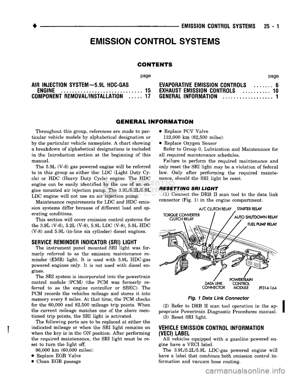
(1) Connect
the
DRB
II
scan tool
to
the
data link
connector (Fig.
1)
in
the engine compartment.
TORQUE CONVERTER
CLUTCH RELAY
A/C
CLUTCH RELAY
.
STARTER RELAY
AUTO
SHUTDOWN RELAY FUEL PUMP RELAY DATA LINK
CONNECTOR POWERTRAIN
CONTROL
MODULE
J9314-164
Fig.
1
Data
Link
Connector
(2) Refer
to
DRB
II
scan tool operation
in
the ap
propriate Powertrain Diagnostic Procedures manual. (3) Reset SRI light.
VEHICLE
EMISSION CONTROL INFORMATION
(VECI)
LABEL
All vehicles equipped with
a
gasoline powered
en
gine have
a
VECI label. The 3.9L/5.2L/5.9L LDC-gas powered engine will
have
a
label that combines both emission control
in
formation and vacuum hose routing.
EMISSION CONTROL
SYSTEMS
Page 1481 of 1502
2i
- 4
EMISSION
CONTROL
SYSTEMS
•
VACUUM
HOSE
ROUTING
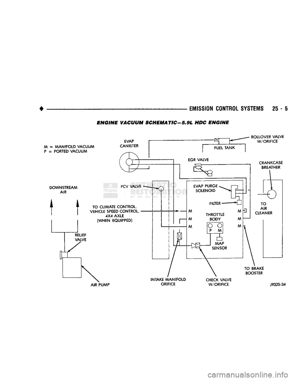
SCHEMATICS
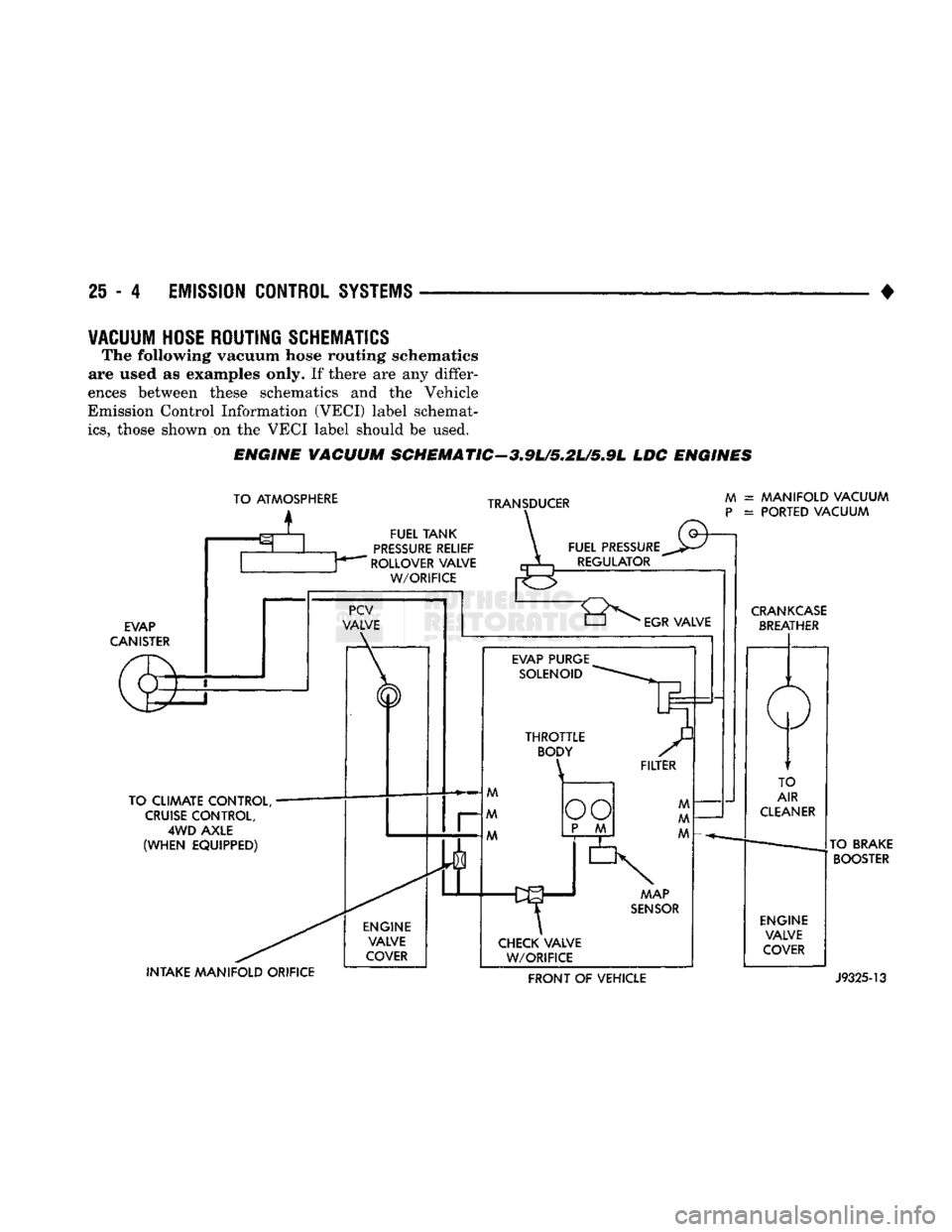
The following vacuum hose routing schematics
are used
as
examples only.
If
there
are any
differ
ences between these schematics
and the
Vehicle
Emission Control Information (VECI) label schemat
ics,
those shown
on the
VECI label should
be
used.
ENGINE
VACUUM
SCHEMATIC-3.9U5.2L/5.9L
LDC
ENGINES
TO ATMOSPHERE
i
TRANSDUCER
FUEL
TANK
PRESSURE
RELIEF
ROLLOVER VALVE
W/ORIFICE
EVAP
CANISTER
TO CLIMATE CONTROL,
CRUISE
CONTROL,
4WD
AXLE
(WHEN
EQUIPPED) INTAKE
MANIFOLD
ORIFICE ENGINE
VALVE
COVER FUEL PRESSURE
REGULATOR
M
P
= MANIFOLD VACUUM
= PORTED VACUUM
"8^
EGR
VALVE
EVAP PURGE SOLENOID MAP
SENSOR
CHECK VALVE W/ORIFICE
CRANKCASE
BREATHER
TO
AIR
CLEANER
ENGINE VALVE
COVER TO BRAKE
BOOSTER FRONT
OF
VEHICLE
J9325-13
Page 1482 of 1502
EMISSION
CONTROL
SYSTEMS
25 • I
ENGINE
VACUUM SCHEMATIC-5,9L HOC ENGINE
M =
MANIFOLD VACUUM
P
=
PORTED VACUUM EVAP
CANISTER
ROLLOVER VALVE
W/ORIFICE
CRANKCASE
BREATHER
DOWNSTREAM
AIR
t t
TO CLIAAATE CONTROL,
VEHICLE
SPEED
CONTROL, 4X4 AXLE
(WHEN
EQUIPPED)
TO BRAKE
BOOSTER
AIR PUMP INTAKE MANIFOLD
ORIFICE
CHECK
VALVE
W/ORIFICE
J9325-34
Page 1485 of 1502
25 - 8
EMISSION
CONTROL
SYSTEMS
•
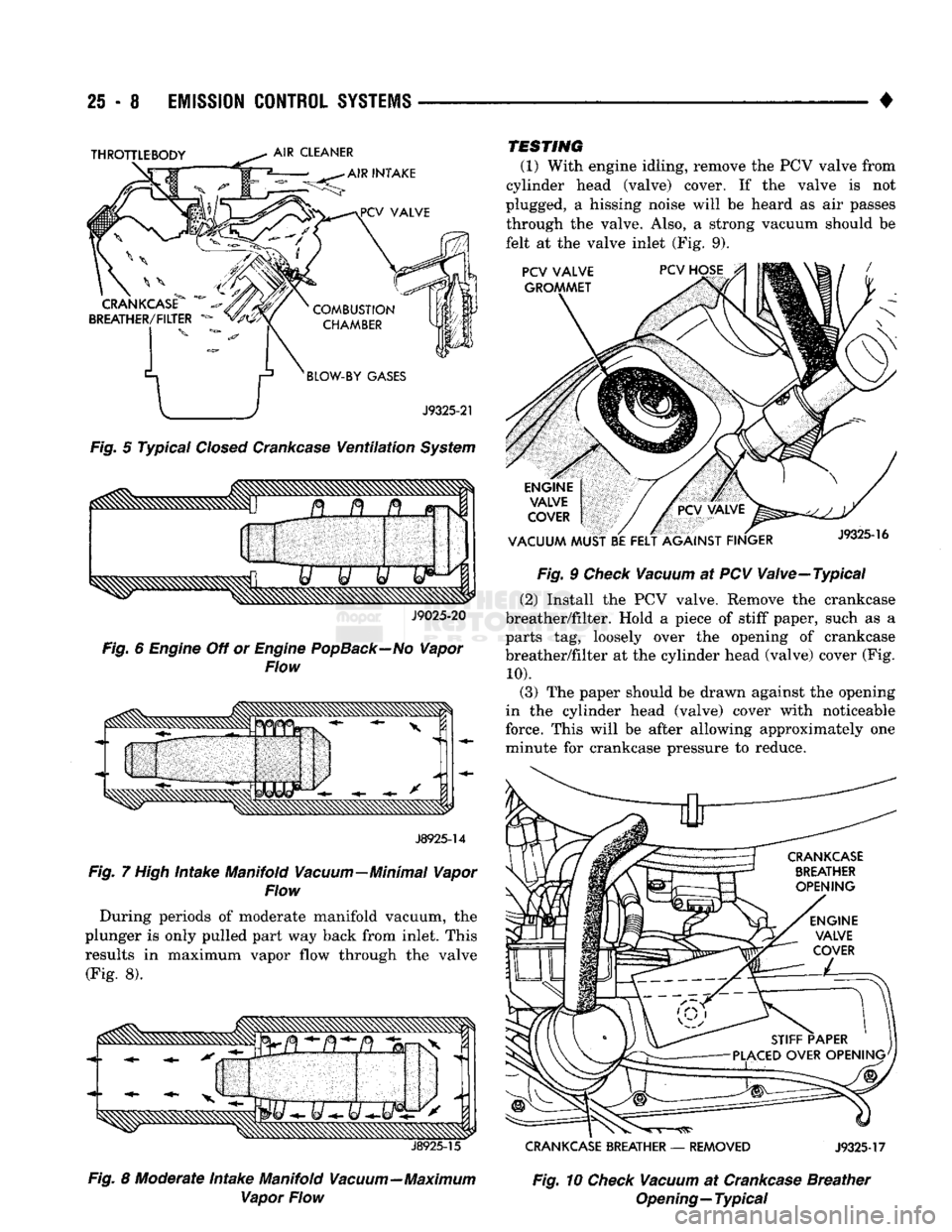
Fig.
5 Typical
Closed
Crankcase
Ventilation
System
J9025-20
Fig.
6
Engine
Off or
Engine
PopBack—No
Vapor
Flow
J8925-14
Fig.
7
High
Intake Manifold Vacuum—Minimal Vapor
Flow
During periods of moderate manifold vacuum, the
plunger is only pulled part way back from inlet. This
results in maximum vapor flow through the valve
(Fig. 8).
J8925-15
Fig.
8 Moderate Intake Manifold Vacuum—Maximum Vapor Flow TESTING
(1) With engine idling, remove the PCV valve from
cylinder head (valve) cover. If the valve is not
plugged, a hissing noise will be heard as air passes through the valve. Also, a strong vacuum should be
felt at the valve inlet (Fig. 9).
Fig.
9
Check
Vacuum
at PCV Valve—Typical
(2) Install the PCV valve. Remove the crankcase
breather/filter. Hold a piece of stiff paper, such as a
parts tag, loosely over the opening of crankcase
breather/filter at the cylinder head (valve) cover (Fig.
10).
(3) The paper should be drawn against the opening
in the cylinder head (valve) cover with noticeable
force. This will be after allowing approximately one minute for crankcase pressure to reduce.
CRANKCASE
BREATHER
—
REMOVED
J9325-17
Fig.
10
Check
Vacuum
at
Crankcase
Breather
Opening—Typical
Page 1486 of 1502
•
EMISSION
CONTROL
SYSTEMS
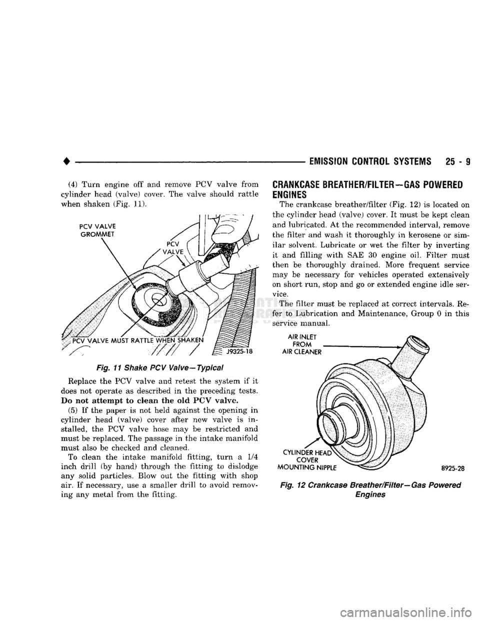
25 - 9 (4) Turn engine off and remove PCV valve from
cylinder head (valve) cover. The valve should rattle
when shaken (Fig. 11).
Fig. 11
Shake
PCV Valve-Typical
Replace the PCV valve and retest the system if it
does not operate as described in the preceding tests.
Do not attempt to clean the old PCV valve.
(5) If the paper is not held against the opening in
cylinder head (valve) cover after new valve is in stalled, the PCV valve hose may be restricted and
must be replaced. The passage in the intake manifold
must also be checked and cleaned. To clean the intake manifold fitting, turn a 1/4
inch drill (by hand) through the fitting to dislodge
any solid particles. Blow out the fitting with shop air. If necessary, use a smaller drill to avoid remov
ing any metal from the fitting.
CRANKCASE
BREATHER/FILTER-GAS POWERED
ENGINES
The crankcase breather/filter (Fig. 12) is located on
the cylinder head (valve) cover. It must be kept clean and lubricated. At the recommended interval, remove
the filter and wash it thoroughly in kerosene or sim ilar solvent. Lubricate or wet the filter by inverting
it and filling with SAE 30 engine oil. Filter must
then be thoroughly drained. More frequent service
may be necessary for vehicles operated extensively on short run, stop and go or extended engine idle ser
vice.
The filter must be replaced at correct intervals. Re
fer to Lubrication and Maintenance, Group 0 in this service manual. 8925-28
Fig. 12 Crankcase Breather/Filter—Gas Powered
Engines
Page 1488 of 1502
•
EMISSION
CONTROL
SYSTEMS
25 - 11 • The electrical solenoid portion of the EET is not
energized.
• The engine back pressure entering the EGR valve
inlet is strong enough to close the transducer bleed
valve.
If back pressure is not strong enough to close the
transducer bleed valve, the transducer will bleed off the vacuum preventing EGR operation.
When the electrical solenoid portion of the EET is
de-energized by the powertrain control module (PCM), vacuum flows to the transducer. The trans
ducer is connected to the engine exhaust system by a small hose that connects to the base of the EGR
valve.
The vacuum section of the transducer is controlled
by exhaust system back pressure. When back pres sure is high enough it will close a bleed valve in the
transducer allowing vacuum to actuate the EGR
valve. If back pressure does not close the bleed valve,
vacuum will be bled off.
For more information, refer to Group 14, Fuel Sys
tems.
Refer to the Component Removal/Installation sec
tion of this group for EGR valve replacement proce
dures.
EGR SYSTEM ON-BOARD DIAGNOSTICS
(CALIFORNIA VEHICLES
ONLY)
The powertrain control module (PCM) performs an
On-Board Diagnostic (OBD) check of the EGR system
on all California vehicles. The diagnostic system uses
the electric EGR transducer (EET) for the system
tests.
The OBD check activates only during selected en
gine/driving conditions. When the conditions are met,
the PCM energizes the EET solenoid to disable the EGR. The PCM checks for a change in the oxygen sensor signal. If the air-fuel mixture goes lean, the
PCM will attempt to enrichen the mixture. The PCM
registers a diagnostic trouble code (DTC) if the EGR system has failed or degraded. After registering a
DTC,
the PCM turns the malfunction indicator
lamp (MIL) on. (The malfunction indicator lamp was formerly referred to as the check engine lamp). The
malfunction indicator lamp indicates the need for im
mediate service.
If a malfunction is indicated by the malfunction in
dicator lamp and a DTC for the EGR system was set,
check for proper operation of EGR system. Use the
following: System Test, EGR Gas Flow Test and EGR
Diagnosis Chart.
If the EGR system tests properly, check the system
using the DRB II scan tool. For use of the DRB II,
refer to the appropriate Powertrain Diagnostics Pro cedure service manual. EGR SYSTEM SERVICE
A malfunctioning EGR system can cause engine
spark knock, sags or hesitation, rough idle, engine
stalling and poor driveability. To be sure of proper
operation of the EGR system, inspect all passages for
blockage. Check moving parts for binding. Inspect
the complete system for leaks. Replace system com ponents or hoses that are leaking.
Inspect all hose connections between throttle body,
intake manifold, EGR valve and EGR purge solenoid.
Replace any vacuum harness components that are
leaking or damaged. Refer to EGR Control System Test and EGR Gas
Flow Test to check EGR System operation.
EGR GAS FLOW TEST (1) Disconnect hose from EGR valve and connect a
hand vacuum pump to EGR valve nipple. Apply a
minimum of 12 inches vacuum the valve.
(2) The engine should now idle roughly or stall. If
this occurs, the valve is performing correctly. Proceed
to Electric EGR Transducer Test.
(3) If the engine idle speed did not change, remove
the EGR valve and inspect the valve and the exhaust passage in the manifold for blockage. Repair as nec
essary. If blockage is not present, replace the EGR
valve.
ELECTRIC EGR TRANSDUCER (EET)
TESTING ELECTRIC SOLENOID PORTION OF TRANSDUCER
(1) Bring the engine to normal operating tempera
ture.
Operate at idle speed. Test the EET as follows: (2) Check vacuum at EET vacuum source. Discon
nect the hose and attach a vacuum gauge to it.
(3) Vacuum should be a minimum of 15 inches:
• If vacuum is low, check the line for kinks, twists
or a loose connection at vacuum connector or intake
manifold.
• If vacuum is correct, remove gauge. Connect the
vacuum line and proceed to next step. (4) Check EET operation using the appropriate
Powertrain Diagnostic Procedures service manual.
Refer to this manual for use of the DRB II scan tool and repair EET as necessary.
TESTING VACUUM PORTION
OF
TRANSDUCER
(1) Disconnect the EET vacuum lines, back pres
sure line and electrical connector. Remove trans
ducer.
(2) Plug the EET EGR valve port.
(3) Apply 1-2 pounds air pressure to exhaust back
pressure port. Air pressure can be supplied with a
hand operated air pump or compressed air (regulated
to correct psi).
(4) Apply a minimum of 12 inches of vacuum to
vacuum supply port.
Replace the EET if it will not hold vacuum.