1993 DODGE TRUCK fuel sending unit
[x] Cancel search: fuel sending unitPage 659 of 1502
FLANGE GASKET
X
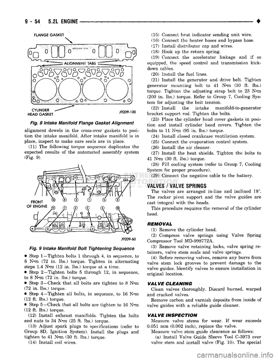
Fig. 8 intake Manifold Flange Gasket Alignment alignment dowels in the cross-over gaskets to posi
tion the intake manifold. After intake manifold is in
place, inspect to make sure seals are in place. (11) The following torque sequence duplicates the
expected results of the automated assembly system (Fig. 9).
J9209-60
Fig. 9 Intake Manifold Bolt Tightening Sequence
• Step
1—Tighten
bolts 1 through 4, in sequence, to
8 N-m (72 in. lbs.) torque. Tighten in alternating
steps 1.4 N-m (12 in. lbs.) torque at a time.
• Step 2—Tighten bolts 5 through 12, in sequence,
to 8 N-m (72 in. lbs.) torque.
• Step 3—Check that all bolts are tighten to 8 N-m (72 in. lbs.) torque.
• Step 4—Tighten all bolts, in sequence, to 16 N-m (12 ft. lbs.) torque.
• Step
5—Check
that all bolts are tighten to 16 N-m (12 ft. lbs.) torque.
(12) Install exhaust manifolds. Tighten the bolts
and nuts to 34 N-m (25 ft. lbs.) torque.
(13) Adjust spark plugs to specifications (refer to
Group 8D, Ignition System). Install the plugs and
tighten to 41 N-m (30 ft. lbs.) torque. (14) Install coil wires. (15) Connect heat indicator sending unit wire.
(16) Connect the heater hoses and bypass hose.
(17) Install distributor cap and wires. (18) Hook up the return spring.
(19) Connect the accelerator linkage and if so
equipped, the speed control and transmission kick-
down cables.
(20) Install the fuel lines.
(21) Install the generator and drive belt. Tighten
generator mounting bolt to 41 N-m (30 ft. lbs.)
torque. Tighten the adjusting strap bolt to 23 N-m (200 in. lbs.) torque. Refer to Group 7, Cooling Sys
tem for adjusting the belt tension.
(22) Install the intake manifold-to-generator
bracket support rod. Tighten the bolts. (23) Place the cylinder head cover gaskets in posi
tion and install cylinder head covers. Tighten the
bolts to 11 N-m (95 in. lbs.) torque.
(24) Install closed crankcase ventilation system.
(25) Connect the evaporation control system.
(26) Install the air cleaner.
(27) Install the heat shields. Tighten the bolts to
41 N-m (30 ft. lbs.) torque. (28) Fill cooling system (refer to Group 7, Cooling
System for proper procedure).
(29) Connect the negative cable to the battery.
VALVES
/
VALVE
SPRINGS
The valves are arranged in-line and inclined 18°.
The rocker pivot support and the valve guides are cast integral with the heads. This procedure requires the removal of the cylinder
head.
REMOVAL (1) Remove the cylinder head.
(2) Compress valve springs using Valve Spring
Compressor Tool MD-998772A.
(3) Remove valve retaining locks, valve spring re
tainers, valve stem seals and valve springs.
(4) Before removing valves, remove any burrs from
valve stem lock grooves to prevent damage to the
valve guides. Identify valves to ensure installation in
original location.
VALVE CLEANING Clean valves thoroughly. Discard burned, warped
and cracked valves. Remove carbon and varnish deposits from inside of
valve guides with a reliable guide cleaner.
VAL VE INSPECTION Measure valve stems for wear. If wear exceeds
0.051 mm (0.002 inch), replace the valve. Measure valve stem guide clearance as follows:
(a) Install Valve Guide Sleeve Tool C-3973 over
valve stem and install valve (Fig. 10). The special
Page 687 of 1502
9
- 82 5.9L
ENGINE
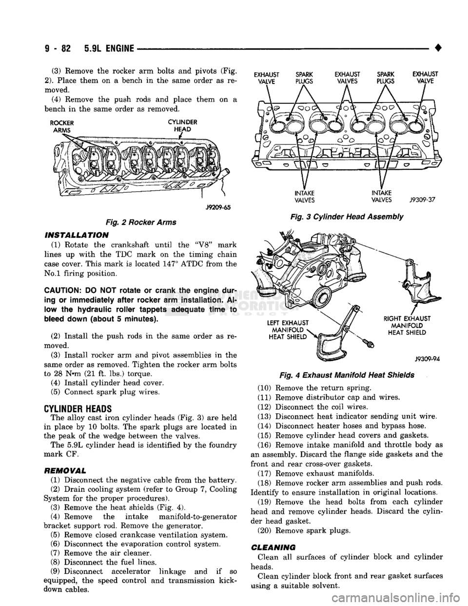
• (3) Remove the rocker arm bolts and pivots (Fig.
2).
Place them on a bench in the same order as re
moved. (4) Remove the push rods and place them on a
bench in the same order as removed.
ROCKER
CYLINDER
J9209-65
Fig.
2
Rocker Arms INSTALLATION
(1) Rotate the crankshaft until the "V8" mark
lines up with the TDC mark on the timing chain
case cover. This mark is located 147° ATDC from the
No.l firing position.
CAUTION:
DO NOT
rotate
or crank the engine dur
ing
or
immediately
after
rocker
arm installation. Al
low the hydraulic roller tappets adequate
time
to
bleed
down
(about 5 minutes).
(2) Install the push rods in the same order as re
moved.
(3) Install rocker arm and pivot assemblies in the
same order as removed. Tighten the rocker arm bolts
to 28 N*m (21 ft. lbs.) torque. (4) Install cylinder head cover.
(5) Connect spark plug wires.
CYLINDER HEADS The alloy cast iron cylinder heads (Fig. 3) are held
in place by 10 bolts. The spark plugs are located in
the peak of the wedge between the valves. The 5.9L cylinder head is identified by the foundry
mark CF.
REMOVAL
(1) Disconnect the negative cable from the battery.
(2) Drain cooling system (refer to Group 7, Cooling
System for the proper procedures).
(3) Remove the heat shields (Fig. 4).
(4) Remove the intake manifold-to-generator
bracket support rod. Remove the generator.
(5) Remove closed crankcase ventilation system. (6) Disconnect the evaporation control system.
(7) Remove the air cleaner.
(8) Disconnect the fuel lines.
(9) Disconnect accelerator linkage and if so
equipped, the speed control and transmission kick- down cables.
EXHAUST SPARK EXHAUST SPARK EXHAUST
VALVE PLUGS VALVES PLUGS VALVE
INTAKE INTAKE
VALVES
VALVES
J9309-37
Fig.
3 Cylinder Head
Assembly
Fig.
4
Exhaust
Manifold Heat
Shields
(10) Remove the return spring.
(11) Remove distributor cap and wires.
(12) Disconnect the coil wires.
(13) Disconnect heat indicator sending unit wire.
(14) Disconnect heater hoses and bypass hose.
(15) Remove cylinder head covers and gaskets.
(16) Remove intake manifold and throttle body as
an assembly. Discard the flange side gaskets and the
front and rear cross-over gaskets.
(17) Remove exhaust manifolds.
(18) Remove rocker arm assemblies and push rods.
Identify to ensure installation in original locations. (19) Remove the head bolts from each cylinder
head and remove cylinder heads. Discard the cylin der head gasket.
(20) Remove spark plugs.
CLEANING
Clean all surfaces of cylinder block and cylinder
heads.
Clean cylinder block front and rear gasket surfaces
using a suitable solvent.
Page 689 of 1502
FLANGE GASKET
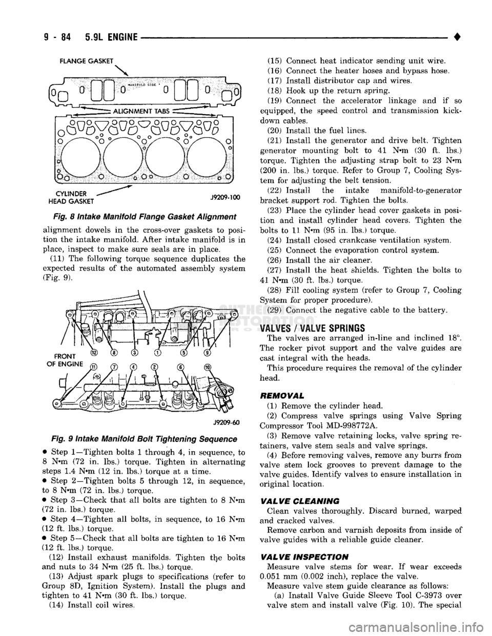
Fig. 8 Intake Manifold Flange Gasket Alignment alignment dowels in the cross-over gaskets to posi
tion the intake manifold. After intake manifold is in
place, inspect to make sure seals are in place.
(11) The following torque sequence duplicates the
expected results of the automated assembly system (Fig. 9).
J9209-60
Fig. 9 Intake Manifold Bolt Tightening Sequence
• Step
1—Tighten
bolts 1 through 4, in sequence, to 8 N-m (72 in. lbs.) torque. Tighten in alternating
steps 1.4 N-m (12 in. lbs.) torque at a time.
• Step 2—Tighten bolts 5 through 12, in sequence,
to 8 N-m (72 in. lbs.) torque. • Step 3—-Check that all bolts are tighten to 8 N-m
(72 in. lbs.) torque.
• Step 4—Tighten all bolts, in sequence, to 16 N-m (12 ft. lbs.) torque.
• Step 5—Check that all bolts are tighten to 16 N-m (12 ft. lbs.) torque.
(12) Install exhaust manifolds. Tighten the bolts
and nuts to 34 N-m (25 ft. lbs.) torque.
(13) Adjust spark plugs to specifications (refer to
Group 8D, Ignition System). Install the plugs and
tighten to 41 N-m (30 ft. lbs.) torque. (14) Install coil wires. (15) Connect heat indicator sending unit wire.
(16) Connect the heater hoses and bypass hose.
(17) Install distributor cap and wires.
(18) Hook up the return spring.
(19) Connect the accelerator linkage and if so
equipped, the speed control and transmission kick-
down cables.
(20) Install the fuel lines.
(21) Install the generator and drive belt. Tighten
generator mounting bolt to 41 N-m (30 ft. lbs.)
torque. Tighten the adjusting strap bolt to 23 N-m (200 In. lbs.) torque. Refer to Group 7, Cooling Sys
tem for adjusting the belt tension.
(22) Install the intake manifold-to-generator
bracket support rod. Tighten the bolts.
(23) Place the cylinder head cover gaskets in posi
tion and install cylinder head covers. Tighten the
bolts to 11 N-m (95 in. lbs.) torque.
(24) Install closed crankcase ventilation system.
(25) Connect the evaporation control system.
(26) Install the air cleaner.
(27) Install the heat shields. Tighten the bolts to
41 N-m (30 ft. lbs.) torque. (28) Fill cooling system (refer to Group 7, Cooling
System for proper procedure).
(29) Connect the negative cable to the battery.
¥AL¥ES
/
WALWE SPRIliS
The valves are arranged in-line and inclined 18°.
The rocker pivot support and the valve guides are cast integral with the heads. This procedure requires the removal of the cylinder
head.
REMOVAL (1) Remove the cylinder head.
(2) Compress valve springs using Valve Spring
Compressor Tool MD-998772A.
(3) Remove valve retaining locks, valve spring re
tainers, valve stem seals and valve springs.
(4) Before removing valves, remove any burrs from
valve stem lock grooves to prevent damage to the
valve guides. Identify valves to ensure Installation in original location,
VALVE
CLEANING Clean valves thoroughly. Discard burned, warped
and cracked valves.
Remove carbon and varnish deposits from Inside of
valve guides with a reliable guide cleaner.
VALVE
INSPECTION Measure valve stems for wear. If wear exceeds
0.051 mm (0.002 Inch), replace the valve.
Measure valve stem guide clearance as follows: (a) Install Valve Guide Sleeve Tool C-3973 over
valve stem and install valve (Fig. 10). The special
Page 772 of 1502
•
EXHAUST SYSTEM
AND
INTAKE MANIFOLD
11-13
TIGHTENING
TORQUE
23
N-m
(200
IN. LBS.)
7
N-m
(65
IN. LBS.)
5 N-m
(40
IN. LBS.)
HEAT
SHIELD CATALYTIC
CONVERTER
LOWER HEAT SHIELD HEAT
SHIELD UPPER
HEAT
SHIELD
CROSSMEMBER
SKID
PLATE
UPPER HEAT SHIELD
(6 IN.
RAIL) CONED WASHER
UPPER HEAT SHIELD
(7 IN.
RAIL)
J9211-21
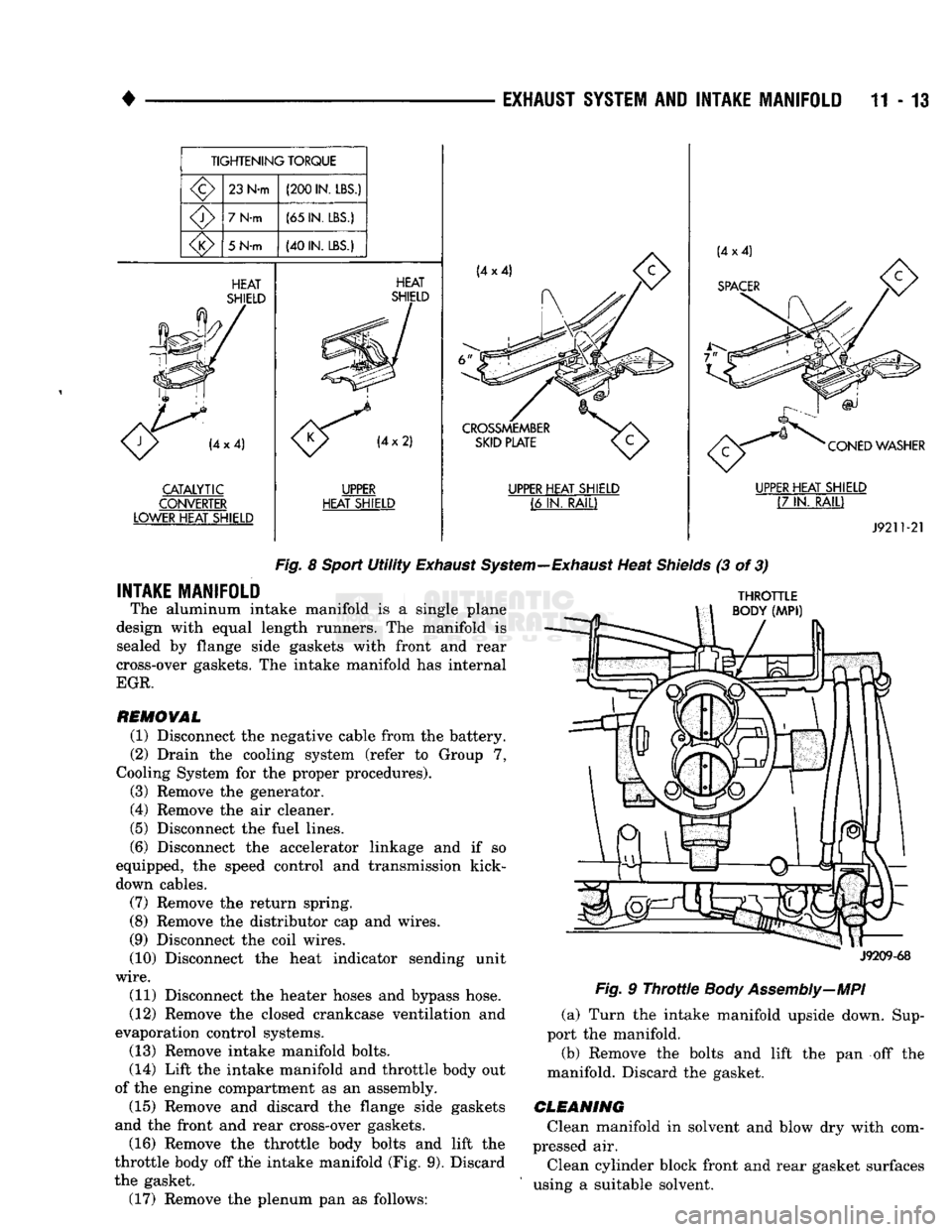
Fig.
8
Sport
Utility
Exhaust
System—Exhaust
Heat
Shields
(3 of 3)
INTAKE MANIFOLD
The aluminum intake manifold is a single plane
design with equal length runners. The manifold is sealed by flange side gaskets with front and rear
cross-over gaskets. The intake manifold has internal
EGR.
REMOVAL
(1) Disconnect the negative cable from the battery.
(2) Drain the cooling system (refer to Group 7,
Cooling System for the proper procedures).
(3) Remove the generator.
(4) Remove the air cleaner.
(5) Disconnect the fuel lines.
(6) Disconnect the accelerator linkage and if so
equipped, the speed control and transmission kick-
down cables.
(7) Remove the return spring.
(8) Remove the distributor cap and wires.
(9) Disconnect the coil wires.
(10) Disconnect the heat indicator sending unit
wire.
(11) Disconnect the heater hoses and bypass hose.
(12) Remove the closed crankcase ventilation and
evaporation control systems. (13) Remove intake manifold bolts.
(14) Lift the intake manifold and throttle body out
of the engine compartment as an assembly. (15) Remove and discard the flange side gaskets
and the front and rear cross-over gaskets.
(16) Remove the throttle body bolts and lift the
throttle body off the intake manifold (Fig. 9). Discard
the gasket. (17) Remove the plenum pan as follows:
THROTTLE
BODY
(MPI)
J9209-68
Fig.
9
Throttle
Body Assembly—MPI
(a) Turn the intake manifold upside down. Sup
port the manifold.
(b) Remove the bolts and lift the pan off the
manifold. Discard the gasket.
CLEANING
Clean manifold in solvent and blow dry with com
pressed air.
Clean cylinder block front and rear gasket surfaces
using a suitable solvent.
Page 774 of 1502
EXHAUST SYSTEM
AND
INTAKE MANIFOLD
11-15
FLANGE GASKET
o
o
CYLINDER
HEAD GASKET
J9209-101
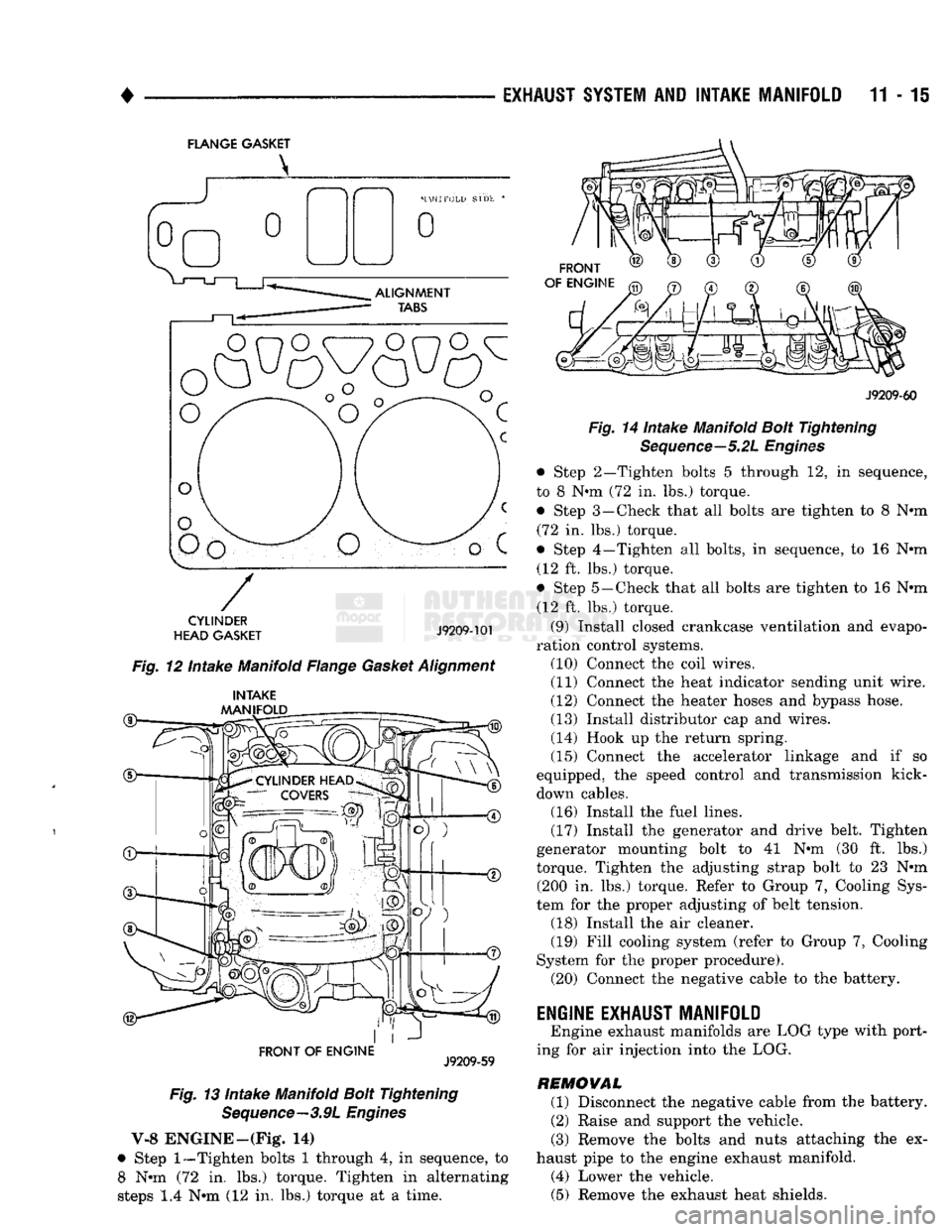
Fig. 12 Intake Manifold Flange Gasket Alignment
®— INTAKE
MANIFOLD
FRONT OF
ENGINE
J9209-59
Fig. 13 Intake Manifold Bolt Tightening Sequence—3.9L Engines
V-8 ENGINE—(Fig* 14)
• Step
1—Tighten
bolts 1 through 4, in sequence, to 8 Nun (72 in. lbs.) torque. Tighten in alternating
steps 1.4 Nun (12 in. lbs.) torque at a time.
FRONT
OF ENGINE
J9209-60
Fig. 14 Intake Manifold Bolt Tightening Sequence—5.2L Engines
• Step 2—Tighten bolts 5 through 12, in sequence,
to 8 Nun (72 in. lbs.) torque. • Step 3—Check that all bolts are tighten to 8 Nun (72 in. lbs.) torque.
• Step 4—Tighten all bolts, in sequence, to 16 Nun (12 ft. lbs.) torque.
• Step 5—Check that all bolts are tighten to 16 Nun (12 ft. lbs.) torque.
(9) Install closed crankcase ventilation and evapo
ration control systems. (10) Connect the coil wires.
(11) Connect the heat indicator sending unit wire.
(12) Connect the heater hoses and bypass hose.
(13) Install distributor cap and wires.
(14) Hook up the return spring.
(15) Connect the accelerator linkage and if so
equipped, the speed control and transmission kick-
down cables. (16) Install the fuel lines,
(17) Install the generator and drive belt. Tighten
generator mounting bolt to 41 Nun (30 ft. lbs.)
torque. Tighten the adjusting strap bolt to 23 Nun (200 in. lbs.) torque. Refer to Group 7, Cooling Sys
tem for the proper adjusting of belt tension. (18) Install the air cleaner. (19) Fill cooling system (refer to Group 7, Cooling
System for the proper procedure). (20) Connect the negative cable to the battery.
ENGINE EXHAUST MANIFOLD
Engine exhaust manifolds are LOG type with port
ing for air injection into the LOG.
REMOVAL (1) Disconnect the negative cable from the battery.
(2) Raise and support the vehicle.
(3) Remove the bolts and nuts attaching the ex
haust pipe to the engine exhaust manifold. (4) Lower the vehicle. (5) Remove the exhaust heat shields.
Page 820 of 1502
•
FUEL
SYSTEM
14 - 1
FUEL
SYSTEM
page
ACCELERATOR
PEDAL
AND THROTTLE
CABLE
................ 25
DIESEL
FUEL
INJECTION-COMPONENT
DESCRIPTION/SYSTEM
OPERATION
76
DIESEL
FUEL
INJECTION-GENERAL
DIAGNOSIS
88
DIESEL
FUEL
INJECTION-SERVICE
PROCEDURES
....................... 106
FUEL
DELIVERY
SYSTEM-EXCEPT
DIESEL
.. 3
FUEL
DELIVERY-DIESEL
ENGINE
15
FUEL
TANKS
.... 20
page
GENERAL
INFORMATION 1
MULTI-PORT
FUEL
INJECTION (MPI)-
COMPONENT
DESCRIPTION/SYSTEM
OPERATION-EXCEPT
DIESEL
29
MULTI-PORT
FUEL
INJECTION (MPI)-
COMPONENT
REMOVAL/INSTALLATION-
EXCEPT
DIESEL
64
MULTI-PORT
FUEL
INJECTION (MPI)-
GENERAL
DIAGNOSIS-EXCEPT
DIESEL
...43
SERVICE
ADJUSTMENTS-DIESEL
122
SPECIFICATIONS
123
GENERAL INFORMATION
Throughout this group, references are made to par
ticular vehicle models by alphabetical designation or
by the particular vehicle nameplate. A chart showing a breakdown of the alphabetical designations is in
cluded in the Introduction section at the beginning of
this manual.
The 5.9L (V-8) gas powered engine will be referred
to in this group as either the: LDC (Light Duty Cy cle) or HDC (Heavy Duty Cycle) engine. The HDC engine can be easily identified by the use of an en
gine mounted air injection pump. The 3.9L/5.2L/5.9L
LDC engine will not use an air injection pump.
This Fuel System group will cover all fuel system
components for the 3.9L (V-6), 5.2L (V-8), 5.9L LDC
(V-8),
5.9L HDC (V-8) and 5.9L (in-line six cylinder)
diesel engines.
The Fuel System consists of: the fuel tank, an
electric (fuel tank mounted) fuel pump and fuel fil
ter. It also consists of fuel tubes/lines/hoses, vacuum
hoses,
throttle body and fuel injector(s).
The Fuel Delivery System consists of: the electric
fuel pump, fuel filter, fuel tubes/lines/hoses, fuel rail,
fuel injectors and fuel pressure regulator.
A Fuel Return System is used on all vehicles (all
engines) except the 5.9L (V-8) gas powered engine. On this engine, a returnless type fuel system is
used. The fuel return system consists of fuel tubes/
lines and hoses that route fuel back to the fuel tank.
The Fuel Tank Assembly consists of: the fuel
tank, filler tube, fuel gauge sending unit/electric fuel
pump module, a pressure relief/rollover valve and a
pressure-vacuum filler cap. Also to be considered part of the fuel system is the
Evaporation Control System. This is designed to
reduce the emission of fuel vapors into the atmo sphere. The description and function of the Evapora
tive Control System is found in Group 25, Emission Control Systems.
FUEL
USAGE
STATEMENT-GAS
ENGINES
Your vehicle was designed to meet all emission
regulations and provide excellent fuel economy using
high quality unleaded gasoline. Only use unleaded gasolines having a minimum posted octane of 87. If your vehicle develops occasional light spark
knock (ping) at low engine speeds, this is not harm
ful.
However, continued heavy knock at high speeds can cause damage and should be re
ported to your dealer immediately. Engine dam age as a result of heavy knock operation may not be
covered by the new vehicle warranty. In addition to using unleaded gasoline with the
proper octane rating, those that contain deter
gents,
corrosion and stability additives are rec
ommended. Using gasolines that have these additives will help improve fuel economy, reduce
emissions and maintain vehicle performance. Gener ally, premium unleaded gasolines contain more addi
tive than regular unleaded gasolines. Poor quality gasoline can cause problems such as
hard starting, stalling and stumble. If you experience
these problems, use another brand of gasoline before considering service for the vehicle.
Page 822 of 1502
•
FUEL SYSTEM
14 • 3
FUEL
DELIVERY SYSTEM-EXCEPT DIESEL
INDEX
page
Fuel Filter—3.9L/5.2L Gas Engine
............
10
Fuel
Filter—5.9L
Gas Engine
11
Fuel Pressure Leak Down Test—3.9L/5.2L Engine
. 8
Fuel Pressure Leak Down Test—5.9L Engine
.... 9
Fuel Pump Capacity
Test—All
Gas
Engines
..... 8
Fuel Pump
Control
........................
5
Fuel Pump Module—3.9L/5.2L Engines
3
GENERAL INFORMATION
Two different types
of
fuel delivery/fuel return sys
tems
are
used.
The
system used with
the
3.9L/5.2L
engine will route excess fuel pressure back
to the
fuel tank through
a
fuel return line.
The
system used
with
the 5.9L
engine will
not
have
a
separate fuel
re
turn line. This system will
be
referred
to as a re-
turnless type.
The
fuel pump module used with
the
5.9L engine will contain
a
combination fuel pressure
regulator
and
fuel filter. Refer
to the
following Fuel
Pump Module
for
additional information
or,
refer
to
the Multi-Port Fuel Injection sections
of
this Fuel System group. A separate frame mounted fuel filter will
not be
used with
any 5.9L gas
powered engine.
FUEL
PUMP
M0DULE-3.9L/5.2L
ENGINES
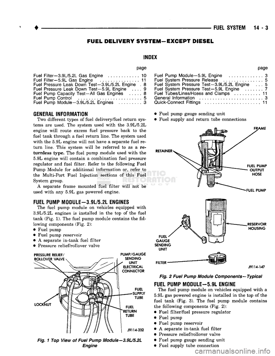
The fuel pump module
on
vehicles equipped with
3.9L/5.2L engines
is
installed
in the top of the
fuel
tank (Fig.
1). The
fuel pump module contains
the
fol lowing components (Fig.
2):
• Fuel pump
• Fuel pump reservoir
•
A
separate in-tank fuel filter
• Pressure relief/rollover valve
PRESSURE
RELIEF/
PUMP/GAUGE
Fig.
1
Top View
of
Fuel
Pump
Module—3.9U5.2L
Engine
page
Fuel Pump Module—5.9L Engine
.............
3
Fuel System Pressure Release
...............
5
Fuel System Pressure Test—3.9L/5.2L Engine
... 5
Fuel System Pressure Test—5.9L Engine
7
Fuel Tubes/Lines/Hoses
and
Clamps
..........
11
General
Information
3
Quick-Connect
Fittings
11
• Fuel pump gauge sending unit
• Fuel supply
and
return tube connections
J9114-147
Fig.
2
Fuel
Pump
Module
Components—Typical
FUEL PUMP MODULE—5.9L ENGINE
The fuel pump module
on
vehicles equipped with
a
5.9L
gas
powered engine
is
installed
in the top of
the
fuel tank
(Fig. 3). The
fuel pump module contains
the following components (Fig.
2):
• Fuel filter/fuel pressure regulator
• Fuel pump • Fuel pump reservoir
•
A
separate in-tank fuel filter
• Pressure relief/rollover valve
• Fuel pump gauge sending unit
• Fuel supply tube connection
Page 823 of 1502
14-4
FUEL
SYSTEM
•
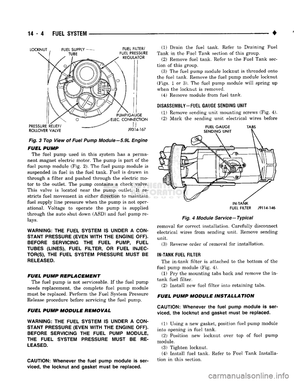
Fig.
3 Top View of
Fuel
Pump
Module—5.9L
Engine
FUEL
PUMP
The fuel pump used in this system has a perma
nent magnet electric motor. The pump is part of the
fuel pump module (Fig. 2). The fuel pump module is suspended in fuel in the fuel tank. Fuel is drawn in
through a filter and pushed through the electric mo
tor to the outlet. The pump contains a check valve.
This valve is located near the pump outlet. It re stricts fuel movement in either direction to maintain
fuel supply line pressure when the pump is not oper ational. Voltage to operate the pump is supplied
through the auto shut down (ASD) and fuel pump re
lays.
WARNING:
THE
FUEL SYSTEM
IS
UNDER
A
CON STANT PRESSURE (EVEN
WITH
THE
ENGINE OFF).
BEFORE
SERVICING
THE
FUEL PUMP, FUEL
TUBES
(LINES), FUEL FILTER,
OR
FUEL
INJEC
TOR^),
THE
FUEL SYSTEM PRESSURE MUST
BE
RELEASED.
FUEL
PUMP
REPLACEMENT
The fuel pump is not serviceable. If the fuel pump
needs replacement, the complete fuel pump module must be replaced. Perform the Fuel System Pressure
Release procedure before servicing the fuel pump.
FUEL
PUMP
MODULE
REMOVAL
WARNING:
THE
FUEL SYSTEM
IS
UNDER
A
CON STANT PRESSURE (EVEN
WITH
THE
ENGINE OFF).
BEFORE
SERVICING
THE
FUEL PUMP MODULE,
THE FUEL SYSTEM PRESSURE MUST
BE RE
LEASED.
CAUTION:
Whenever
the
fuel
pump
module
is
ser
viced,
the
locknut
and gasket
must
be replaced. (1) Drain the fuel tank. Refer to Draining Fuel
Tank in the Fuel Tank section of this group.
(2) Remove fuel tank. Refer to the Fuel Tank sec
tion of this group.
(3) The fuel pump module locknut is threaded onto
the fuel tank. Remove the fuel pump module locknut
(Figs.
1 or 3). The fuel pump module will spring up
when the locknut is removed.
(4)
Remove module from fuel tank.
DISASSEMBLY-
FUEL GAUGE SENDING
UNIT
(1) Remove sending unit mounting screws (Fig. 4).
(2) Mark the sending unit electrical wires before
FUEL
GAUGE
TABS
IN-TANK
FUEL
FILTER
J9114-146
Fig.
4
Module
Service—Typical
removal for correct installation. Carefully disconnect electrical wires from sending unit. Remove sending unit.
(3) Reverse order of removal for installation.
IN-TANK FUEL FILTER
The in-tank filter is attached to the bottom of the
fuel pump module (Fig. 4).
(1) Pry the mounting tabs back and remove the in-
tank fuel filter.
(2) Install new fuel filter into retaining tabs.
FUEL
PUMP
MODULE
INSTALLATION
CAUTION:
Whenever
the
fuel
pump
module
is
ser
viced,
the
locknut
and
gasket must
be
replaced.
(1) Using a new gasket, position fuel pump module
into opening in fuel tank. (2) Position new locknut over top of fuel pump
module. (3) Tighten locknut. (4) Install fuel tank. Refer to Fuel Tank Installa
tion in this section.