1993 DODGE TRUCK ad blue
[x] Cancel search: ad bluePage 660 of 1502
•
5.2L
ENGINE
I - 55
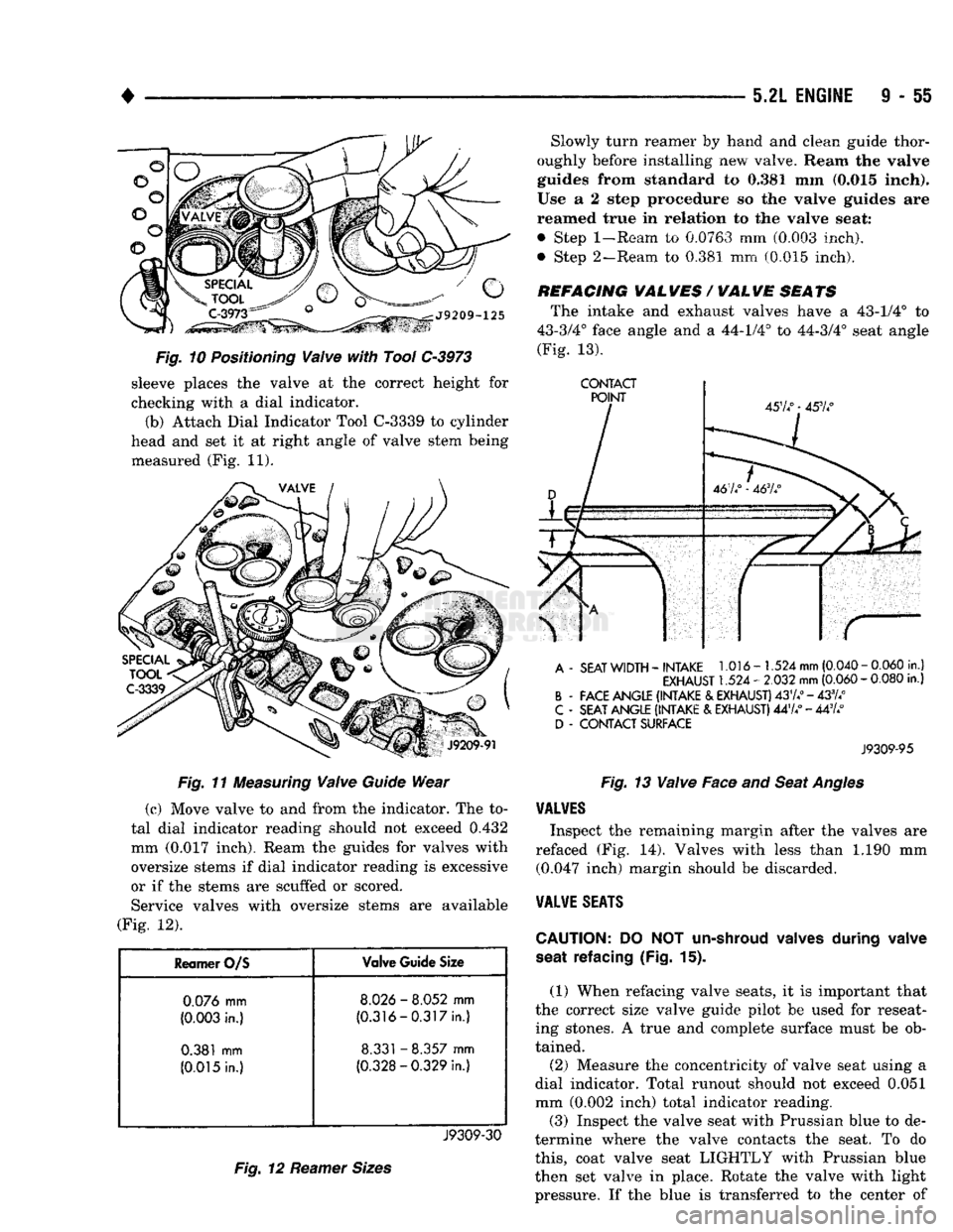
Fig. 10 Positioning Valve with Tool C-3973 sleeve places the valve at the correct height for
checking with a dial indicator.
(b) Attach Dial Indicator Tool C-3339 to cylinder
head and set it at right angle of valve stem being measured (Fig. 11).
Fig. 11 Measuring Valve Guide Wear
(c) Move valve to and from the indicator. The to
tal dial indicator reading should not exceed
0.432
mm
(0.017
inch). Ream the guides for valves with
oversize stems if dial indicator reading is excessive
or if the stems are scuffed or scored. Service valves with oversize stems are available
(Fig. 12).
Reamer
O/S
Valve
Guide
Size
0.076
mm
8.026
-
8.052
mm
(0.003
in.)
(0.316-0.317in.)
0.381
mm
8.331
-
8.357
mm
(0.015
In.)
(0.328-0.329
In.)
J9309-30
Fig. 12 Reamer Sizes
Slowly turn reamer
by
hand
and
clean guide thor
oughly before installing
new
valve. Ream
the valve
guides from standard
to 0,381 mm
(0.015 Inch).
Use
a 2
step procedure
so the
valve guides
are
reamed true
in
relation
to the
valve seat:
• Step
1-Ream
to 0.0763 mm (0.003 inch),
• Step 2—Ream, to 0.381 mm (0.015 inch).
REFACING
VAL
WES
/
WAL
WE
SEATS
The intake and exhaust valves have a 43-1/4° to
43-3/4° face angle and a 44-1/4° to 44-3/4° seat angle
(Fig.
13).
CONTACT
A
-
SEAT
WIDTH
-
INTAKE
1.016-1.524
mm
(0.040
-
0.060
in.)
EXHAUST
1.524 -
2.032
mm
(0.060
-
0.080
in.)
B
-
FACE ANGLE (INTAKE
&
EXHAUST)
437.°
-433//
C
-
SEAT ANGLE (INTAKE
&
EXHAUST)
447/ - 447/
D
-
CONTACT SURFACE
J9309-95
Fig. 13 Valve Face and Seat Angles
VALVES
Inspect the remaining margin after the valves are
refaced (Fig. 14). Valves with less than 1.190 mm (0.047 inch) margin should be discarded.
VALVE
SEATS
CAUTION:
DO NOT
un-shroud valves
during
valve
seat
refacing (Fig.
15).
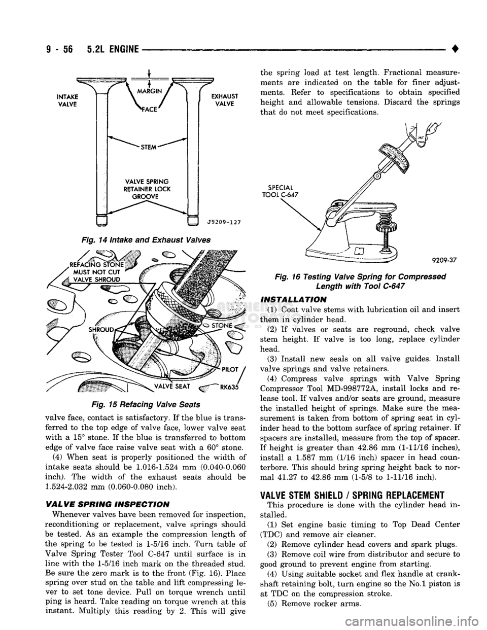
(1) When refacing valve seats, it is important that
the correct size valve guide pilot be used for reseat ing stones. A true and complete surface must be ob
tained.
(2) Measure the concentricity of valve seat using a
dial indicator. Total runout should not exceed 0.051
mm (0.002 inch) total indicator reading. (3) Inspect the valve seat with Prussian blue to de
termine where the valve contacts the seat. To do
this,
coat valve seat LIGHTLY with Prussian blue
then set valve in place. Rotate the valve with light
pressure. If the blue is transferred to the center of
Page 661 of 1502
9
- 56 5.2L
ENGINE
•
VALVE
SPRING
RETAINER LOCK GROOVE
EXHAUST
VALVE
J9209-127 the spring load at test length. Fractional measure
ments are indicated on the table for finer adjust
ments. Refer to specifications to obtain specified
height and allowable tensions. Discard the springs
that do not meet specifications.
SPECIAL
TOOL
C-647
Fig.
14 Intake and
Exhaust
Valves
Fig.
15 Refacing
Valve
Seats
valve face, contact is satisfactory. If the blue is trans
ferred to the top edge of valve face, lower valve seat
with a 15° stone. If the blue is transferred to bottom edge of valve face raise valve seat with a 60° stone.
(4) When seat is properly positioned the width of
intake seats should be
1.016-1.524
mm (0.040-0.060
inch).
The width of the exhaust seats should be
1.524-2.032
mm (0.060-0.080 inch).
WALVE SPRING INSPECTION Whenever valves have been removed for inspection,
reconditioning or replacement, valve springs should
be tested. As an example the compression length of
the spring to be tested is
1-5/16
inch. Turn table of Valve Spring Tester Tool C-647 until surface is in line with the
1-5/16
inch mark on the threaded stud.
Be sure the zero mark is to the front (Fig. 16). Place spring over stud on the table and lift compressing le
ver to set tone device. Pull on torque wrench until ping is heard. Take reading on torque wrench at this instant. Multiply this reading by 2. This will give ^
9209-37
Fig.
16 Testing
Valve
Spring
for
Compressed
Length
with
Tool
C-647
INSTALLATION
(1) Coat valve stems with lubrication oil and insert
them in cylinder head.
(2) If valves or seats are reground, check valve
stem height. If valve is too long, replace cylinder
head.
(3) Install new seals on all valve guides. Install
valve springs and valve retainers.
(4) Compress valve springs with Valve Spring
Compressor Tool MD-998772A, install locks and re
lease tool. If valves and/or seats are ground, measure
the installed height of springs. Make sure the mea surement is taken from bottom of spring seat in cyl
inder head to the bottom surface of spring retainer. If spacers are installed, measure from the top of spacer.
If height is greater than 42.86 mm (1-11/16 inches),
install a 1.587 mm (1/16 inch) spacer in head coun-
terbore. This should bring spring height back to nor mal 41.27 to 42.86 mm (1-5/8 to
1-11/16
inch).
VALVE STEM SHIELD
/
SPRING REPLACEMENT
# This procedure is done with the cylinder head in
stalled. (1) Set engine basic timing to Top Dead Center
(TDC) and remove air cleaner. (2) Remove cylinder head covers and spark plugs.
(3) Remove coil wire from distributor and secure to
good ground to prevent engine from starting. (4) Using suitable socket and flex handle at crank
shaft retaining bolt, turn engine so the No.l piston is
at TDC on the compression stroke. (5) Remove rocker arms.
Page 690 of 1502
•
5.9L
ENGINE
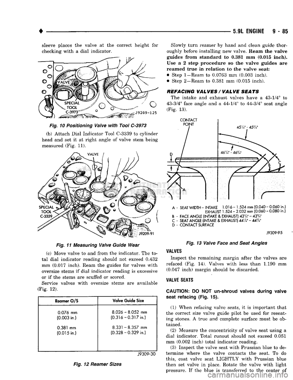
9 - 85 sleeve places the valve at the correct height for
checking with a dial indicator.
Fig.
11
Measuring
Valve
Guide
Wear
(c) Move valve to and from the indicator. The to
tal dial indicator reading should not exceed 0.432
mm (0.017 inch). Ream the guides for valves with
oversize stems if dial indicator reading is excessive
or if the stems are scuffed or scored. Service valves with oversize stems are available
(Fig. 12).
Reamer O/S Valve Guide Size
0.076
mm
8.026
-
8.052
mm
(0.003
in.)
(0.316-0.317
in.)
0.381
mm
8.331
-
8.357
mm
(0.015
in.)
(0.328-0.329
in.)
J9309-30
Fig.
12
Reamer
Sizes
Slowly turn reamer by hand and clean guide thor
oughly before installing new valve. Ream the valve
guides from standard to 0.381 mm (0.015 inch).
Use a 2 step procedure so the valve guides are
reamed true in relation to the valve seat:
• Step
1-Ream
to 0.0763 mm (0.003 inch).
• Step 2-Ream to 0.381 mm (0.015 inch).
REFACING VALVES / VALVE SEATS The intake and exhaust valves have a 43-1/4° to
43-3/4° face angle and a 44-1/4° to 44-3/4° seat angle (Fig. 13).
CONTACT
A
-
SEAT
WIDTH
-
INTAKE
1.016-1.524
mm
(0.040
-
0.060
in.)
EXHAUST
1.524 -
2.032
mm
(0.060
-
0.080
in.)
B
-
FACE ANGLE (INTAKE
&
EXHAUST)
4374°-433/4°
C
-
SEAT ANGLE (INTAKE
&
EXHAUST)
447/ - 443A°
D
-
CONTACT SURFACE
J9309-95
Fig.
13
Valve
Face and
Seat
Angles
VALVES
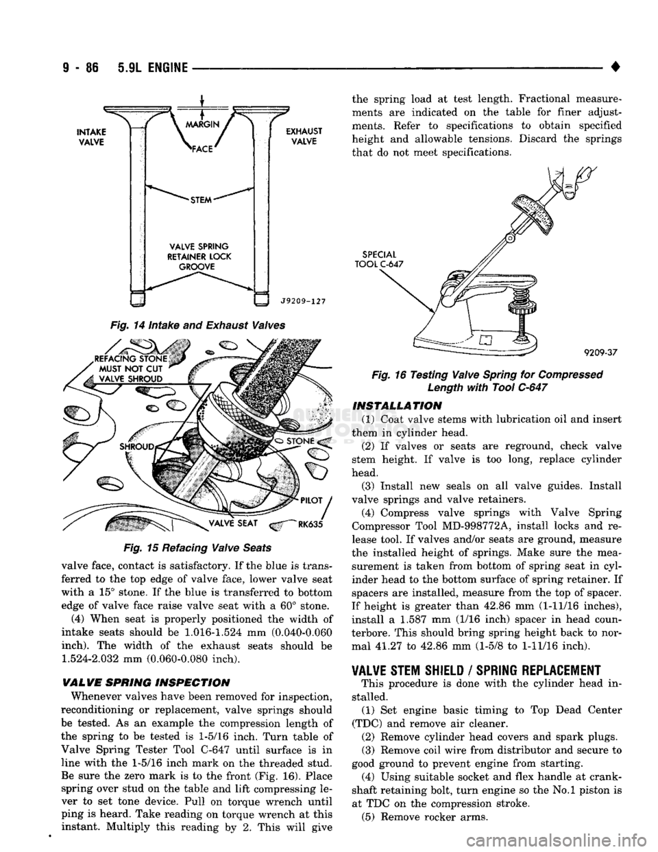
Inspect the remaining margin after the valves are
refaced (Fig. 14). Valves with less than 1.190 mm (0.047 inch) margin should be discarded.
VALVE
SEATS
CAUTION:
DO NOT
un-shroud valves during valve
seat refacing
(Fig. 15).
(1) When refacing valve seats, it is important that
the correct size valve guide pilot be used for reseat ing stones. A true and complete surface must be ob
tained.
(2) Measure the concentricity of valve seat using a
dial indicator. Total runout should not exceed 0.051
mm (0.002 inch) total indicator reading.
(3)
Inspect the valve seat with Prussian blue to de
termine where the valve contacts the seat. To do
this,
coat valve seat LIGHTLY with Prussian blue
then set valve in place. Rotate the valve with light pressure. If the blue is transferred to the center of
Page 691 of 1502
9
• 86 5.9L
ENGINE
•
INTAKE
VALVE
\
MARGIN
/ >
\ACE^
*
STEM
*
VALVE
SPRING
RETAINER
LOCK
GROOVE EXHAUST
VALVE
J9209-127
Fig.
14
intake
and
Exhaust
Waives
REFACING STONE MUST
NOT CUT
VALVE SHROUD Fig.
15 Refacing
Waive
Seats
valve face, contact is satisfactory. If the blue is trans ferred to the top edge of valve face, lower valve seat
with a 15° stone. If the blue is transferred to bottom edge of valve face raise valve seat with a 60° stone.
(4) When seat is properly positioned the width of
intake seats should be
1.016-1.524
mm (0.040-0.060
inch).
The width of the exhaust seats should be
1.524-2.032
mm (0.060-0.080 inch).
VALVE
SPRING
INSPECTION
Whenever valves have been removed for inspection,
reconditioning or replacement, valve springs should be tested. As an example the compression length of
the spring to be tested is
1-5/16
inch. Turn table of
Valve Spring Tester Tool C-647 until surface is in
line with the
1-5/16
inch mark on the threaded stud. Be sure the zero mark is to the front (Fig. 16). Place spring over stud on the table and lift compressing le
ver to set tone device. Pull on torque wrench until
ping is heard. Take reading on torque wrench at this instant. Multiply this reading by 2. This will give the spring load at test length. Fractional measure
ments are indicated on the table for finer adjust
ments. Refer to specifications to obtain specified
height and allowable tensions. Discard the springs that do not meet specifications.
SPECIAL
TOOL
C-647
9209-37
Fig.
16 Testing
Waive
Spring
for
Compressed
Length
with
Tool
C-647
INSTALLATION
(1) Coat valve stems with lubrication oil and insert
them in cylinder head.
(2) If valves or seats are reground, check valve
stem height. If valve is too long, replace cylinder
head.
(3) Install new seals on all valve guides. Install
valve springs and valve retainers.
(4) Compress valve springs with Valve Spring
Compressor Tool MD-998772A, install locks and re
lease tool. If valves and/or seats are ground, measure
the installed height of springs. Make sure the mea surement is taken from bottom of spring seat in cyl
inder head to the bottom surface of spring retainer. If
spacers are installed, measure from the top of spacer.
If height is greater than 42.86 mm (1-11/16 inches),
install a 1.587 mm (1/16 inch) spacer in head coun-
terbore. This should bring spring height back to nor mal 41.27 to 42.86 mm (1-5/8 to
1-11/16
inch).
¥AL¥E
STEM SHIELD
/
SPRING REPLACEMENT
This procedure is done with the cylinder head in
stalled. (1) Set engine basic timing to Top Dead Center
(TDC) and remove air cleaner. (2) Remove cylinder head covers and spark plugs. (3) Remove coil wire from distributor and secure to
good ground to prevent engine from starting. (4) Using suitable socket and flex handle at crank
shaft retaining bolt, turn engine so the No.l piston is
at TDC on the compression stroke. (5) Remove rocker arms.
Page 867 of 1502
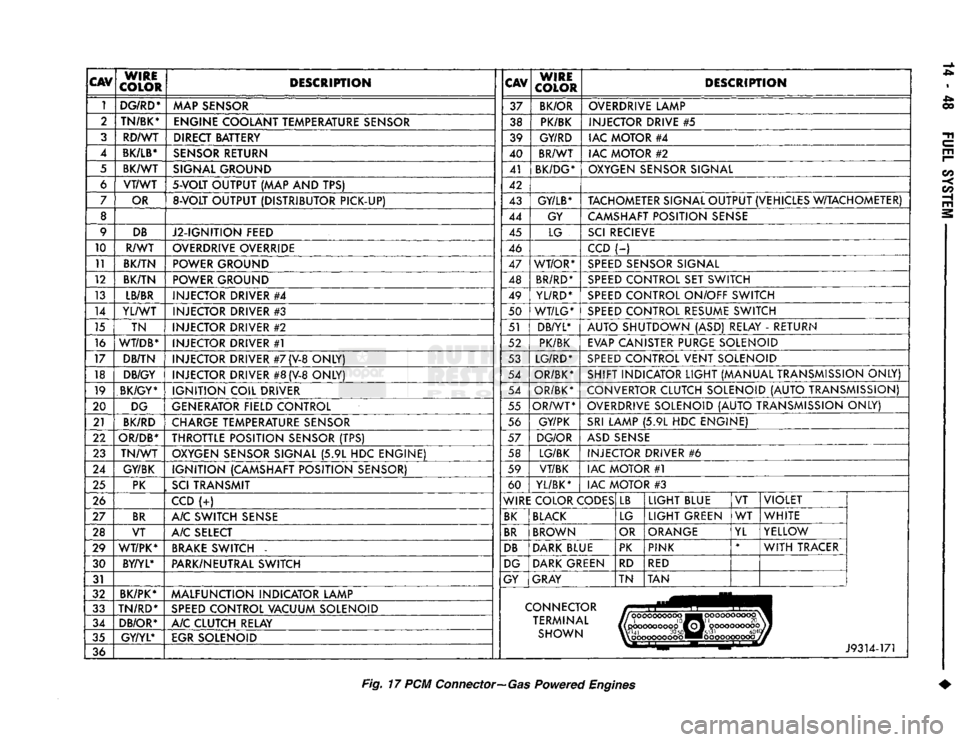
CAV
WIRE
COLOR DESCRIPTION
CAV
WIRE
COLOR DESCRIPTION
1 DG/RD*
MAP SENSOR 37
BK/OR OVERDRIVE LAMP
2 TN/BK*
ENGINE COOLANT TEMPERATURE SENSOR 38 PK/BK INJECTOR DRIVE
#5
3 RD/WT DIRECT BATTERY 39 GY/RD IAC MOTOR
#4
4
BK/LB*
SENSOR RETURN 40 BR/WT
IAC MOTOR
#2
5 BK/WT SIGNAL GROUND 41
BK/DG* OXYGEN SENSOR SIGNAL
6 VT/WT
5-VOLT
OUTPUT
(MAP AND TPS)
42
7 OR
8-VOLT
OUTPUT (DISTRIBUTOR PICK-UP) 43
GY/LB*
TACHOMETER SIGNAL OUTPUT (VEHICLES W/TACHOMETER)
8 44 GY CAMSHAFT POSITION SENSE
9 DB
J2-IGNITION FEED 45
LG SCI RECIEVE
10 R/WT OVERDRIVE OVERRIDE
46 CCD
(-)
11 BK/TN POWER GROUND 47 WT/OR* SPEED SENSOR SIGNAL
12 BK/TN POWER GROUND 48 BR/RD* SPEED CONTROL
SET
SWITCH
13 LB/BR
INJECTOR DRIVER
#4
49
YL/RD* SPEED CONTROL ON/OFF SWITCH
14 YL/WT
INJECTOR DRIVER
#3
50 WT/LG* SPEED CONTROL RESUME SWITCH
15 TN INJECTOR DRIVER
#2
51 DB/YL*
AUTO SHUTDOWN
(ASD)
RELAY
-
RETURN
16
WT/DB*
INJECTOR DRIVER
#1
52 PK/BK
EVAP CANISTER PURGE SOLENOID
17 DB/TN INJECTOR DRIVER
#7
(V-8
ONLY) 53 LG/RD* SPEED CONTROL VENT SOLENOID
18 DB/GY
INJECTOR DRIVER
#8
(V-8
ONLY) 54
OR/BK* SHIFT INDICATOR LIGHT (MANUAL TRANSMISSION ONLY)
19 BK/GY*
IGNITION COIL DRIVER 54
OR/BK* CONVERTOR CLUTCH SOLENOID (AUTO TRANSMISSION)
20 DG
GENERATOR FIELD CONTROL 55
OR/WT OVERDRIVE SOLENOID (AUTO TRANSMISSION ONLY)
21 BK/RD
CHARGE TEMPERATURE SENSOR 56
GY/PK SRI LAMP
(5.9L HDC
ENGINE)
22
OR/DB*
THROTTLE POSITION SENSOR
(TPS)
57
DG/OR ASD SENSE
23 TN/WT
OXYGEN SENSOR SIGNAL
(5.9L HDC
ENGINE) 58 LG/BK
INJECTOR DRIVER
#6
24 GY/BK IGNITION (CAMSHAFT POSITION SENSOR) 59
VT/BK IAC MOTOR
#1
25 PK
,
SCI
TRANSMIT 60
YL/BK* IAC MOTOR
#3
26 CCD
(-:-)
WIRE COLOR CODES LB
LIGHT BLUE
VT VIOLET
27 BR
A/C SWITCH SENSE BK BLACK
LG LIGHT GREEN
WT
WHITE
28 VT A/C SELECT BR BROWN
OR ORANGE
YL YELLOW
29 WT/PK* BRAKE SWITCH
-
DB DARK BLUE PK
PINK *
WITH TRACER
30 BY/YL*
PARK/NEUTRAL SWITCH DG DARK GREEN
RD
RED
31 GY
GRAY TN TAN
32 BK/PK*
MALFUNCTION INDICATOR LAMP
33 TN/RD*
SPEED CONTROL VACUUM SOLENOID CONNECTOR
34 DB/OR* A/C CLUTCH RELAY TERMINAL
|(pcKX>coooop0ffoj'
oooooooooojj
35 GY/YL*
EGR SOLENOID SHOWN W'41
30
50«M#5l31
604
%\
oooooooooo ••ooooooooooj
36 J9314-171
Fig.
17 PCM
Connector—Gas
Powered
Engines
Page 910 of 1502
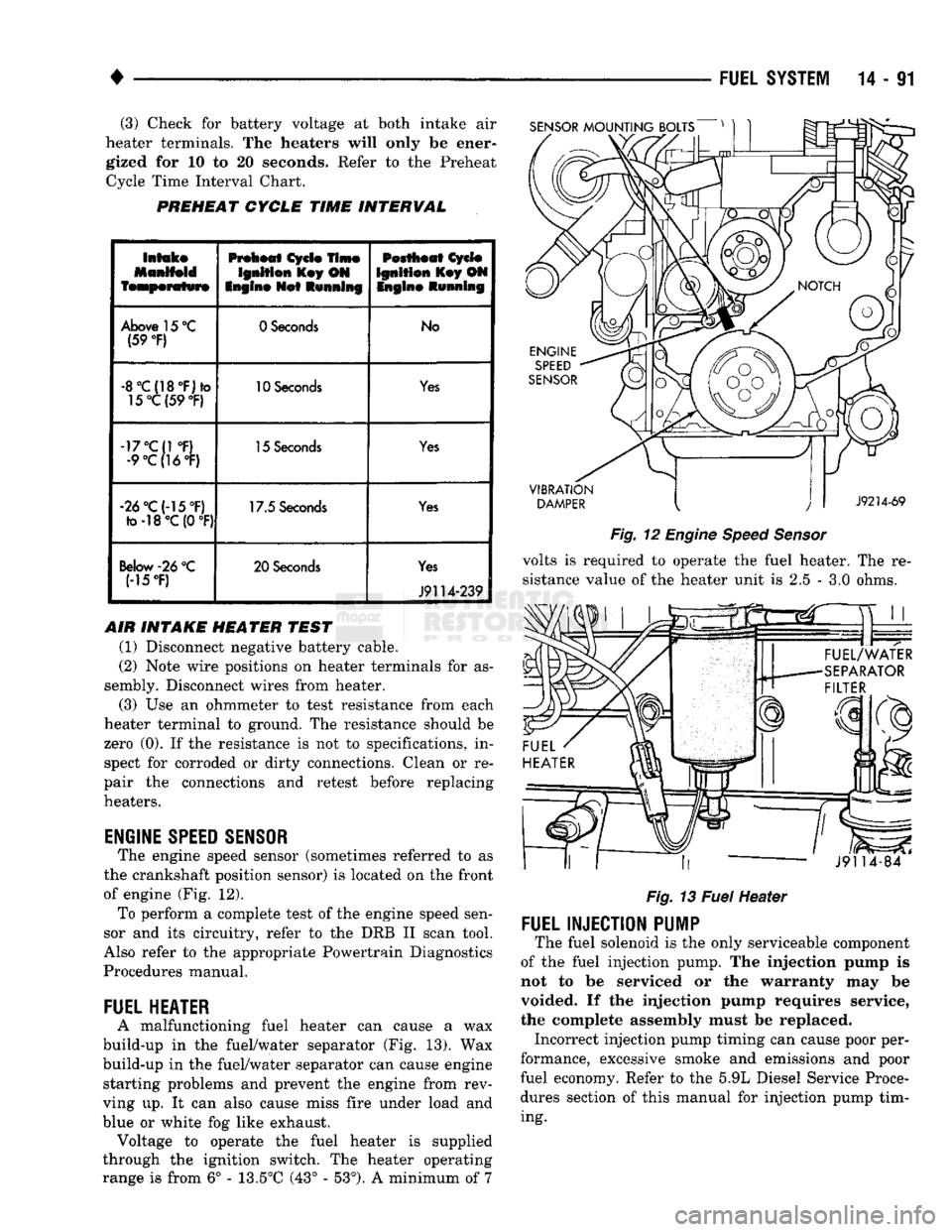
(3) Check for battery voltage at both intake air
heater terminals. The heaters will only be ener gized for 10 to 20 seconds. Refer to the Preheat Cycle Time Interval Chart.
PREHEAT
CYCLE
TIME
INTERVAL
SENSOR
MOUNTING
BOLTS
Intake
Manifold
temperature
Preheat
Cycle
Time
Ignition
Key ON
Engine
Net
Running
Pestheat
Cycle
Ignition
Key ON Ingin©
Running
Above 15 °C (59
°F)
0 Seconds
No
-8°C{18°F)*o 15°C(59
°F)
10 Seconds
Yes
-17°C{1 °F) •9°C(16°F) 15 Seconds
Yes
-26°C(-15°F) fo-18°C (0
°F)
17.5 Seconds
Yes
Below
-26
°C
(15T) 20 Seconds
Yes
J9114-239
AIR INTAKE HEATER TEST (1) Disconnect negative battery cable.
(2) Note wire positions on heater terminals for as
sembly. Disconnect wires from heater.
(3) Use an ohmmeter to test resistance from each
heater terminal to ground. The resistance should be
zero (0). If the resistance is not to specifications, in spect for corroded or dirty connections. Clean or re
pair the connections and retest before replacing
heaters.
ENGINE
SPEED
SENSOR
The engine speed sensor (sometimes referred to as
the crankshaft position sensor) is located on the front
of engine (Fig. 12). To perform a complete test of the engine speed sen
sor and its circuitry, refer to the DRB II scan tool.
Also refer to the appropriate Powertrain Diagnostics
Procedures manual.
FUEL
HEATER
A malfunctioning fuel heater can cause a wax
build-up in the fuel/water separator (Fig. 13). Wax
build-up in the fuel/water separator can cause engine starting problems and prevent the engine from rev
ving up. It can also cause miss fire under load and
blue or white fog like exhaust. Voltage to operate the fuel heater is supplied
through the ignition switch. The heater operating
range is from 6° - 13.5°C (43° - 53°). A minimum of 7
VIBRATION
DAMPER
J9214-69
Fig.
12
Engine
Speed
Sensor
volts is required to operate the fuel heater. The re
sistance value of the heater unit is 2.5 - 3.0 ohms.
««.
* rr ,,
J9114-84
Fig.
13
Fuel
Heater
FUEL
INJECTION
PUMP
The fuel solenoid is the only serviceable component
of the fuel injection pump. The injection pump is
not to be serviced or the warranty may be
voided. If the injection pump requires service,
the complete assembly must be replaced. Incorrect injection pump timing can cause poor per
formance, excessive smoke and emissions and poor
fuel economy. Refer to the 5.9L Diesel Service Proce
dures section of this manual for injection pump tim
ing.
Page 911 of 1502
14-92
FUEL
SYSTEM
• A broken injection pump timing mechanism spring
will cause the timing to be fully advanced resulting
in torque loss, a fuel knock and possible engine over
heating.
An improperly operating KSB (cold start) solenoid
will cause white smoke during engine warm-up. The
KSB solenoid is not serviceable.
A defective or non-adjustable fuel injection pump
can cause starting problems or prevent the engine
from revving up. It can also cause:
• Engine surge at idle • Rough idle (warm engine)
• Engine miss under load
• Low power
• Excessive fuel consumption
• Poor performance
• Low power
• Black smoke from the exhaust • Blue or white fog like exhaust
• Incorrect idle or maximum speed A worn fuel injection pump plunger can effect fuel
pressure and the amount of fuel injected. This results in reduced engine power. In most cases, if the injec
tion pump is delivering fuel from one outlet, it will deliver fuel from all outlets. If the internal plunger is defective, the fuel injection pump must be re
placed.
Engine power is also effected by the governor set
ting and performance. Do not attempt to adjust the governor. If the governor seals on the external adjustment screw are broken, the fuel rate may
be out of adjustment. The warranty of the injec tion pump and the engine may be void if the
seals have been tampered with or removed.
FUEL
INJECTORS
A leaking fuel injector can cause fuel knock, poor
performance, black smoke, poor fuel economy and
rough engine idle. If the fuel injector needle valve
does not operate properly, the engine may misfire and produce low power. A leak in the injection pump-to-injector high pres
sure fuel line can cause many of the same symptoms as a malfunctioning injector. Inspect for a leak in the
high pressure lines before checking for a malfunc
tioning fuel injector.
WARNING:
THE
INJECTION PUMP SUPPLIES HIGH
PRESSURE
FUEL
OF
APPROXIMATELY
59,000
KPA
(8,000
PSI) TO
EACH INDIVIDUAL INJECTOR
THROUGH THE HIGH
PRESSURE
LINES. FUEL UN
DER
THIS AMOUNT
OF
PRESSURE
CAN
PENE
TRATE THE SKIN AND CAUSE PERSONAL INJURY,
WEAR
SAFETY GOGGLES
AND
ADEQUATE PRO
TECTIVE CLOTHING. AVOID CONTACT
WITH
FUEL
SPRAY
WHEN BLEEDING HIGH
PRESSURE
FUEL
LINES.
WARNING:
DO NOT
BLEED
AIR
FROM
THE
FUEL
SYSTEM
OF A
HOT ENGINE.
DO
NOT ALLOW FUEL
TO SPRAY ONTO THE EXHAUST MANIFOLD WHEN
BLEEDING
AIR
FROM THE FUEL SYSTEM.
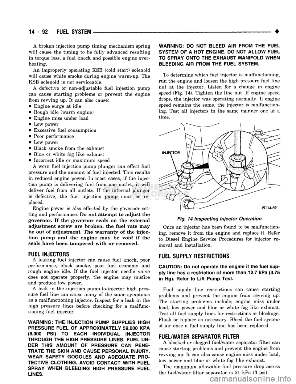
To determine which fuel injector is malfunctioning,
run the engine and loosen the high pressure fuel line nut at the injector. Listen for a change in engine
speed (Fig. 14). Tighten the line nut. If engine speed
drops,
the injector was operating normally. If engine
speed remains the same, the injector is malfunction
ing. Test all injectors in the same manner one at a
time.
Fig. 14
Inspecting
Injector Operation
Once an injector has been found to be malfunction
ing, remove it from the engine and replace it. Refer
to Diesel Engine Service Procedures for injector re moval and installation.
FUEL
SUPPLY
RESTRICTIONS
CAUTION:
Do not
operate
the
engine
if the
fuel
sup ply
line
has
a
restriction
of
more
than
12.7
kPa
(3.75
in
Hg).
Refer
to
Lift
Pump
Test.
Fuel supply line restrictions can cause starting
problems and prevent the engine from revving up.
The starting problems include; engine miss under load, low power and blue or white fog like exhaust.
Test all fuel supply lines for restrictions or blockage.
Flush or replace as necessary. Bleed the fuel system
of air once a fuel supply line has been replaced.
FUEL/WATER
SEPARATOR
FILTER
A blocked or clogged fuel/water separator filter can
cause starting problems and prevent the engine from
revving up. It can also cause engine miss under load,
low power and blue or white fog like exhaust. The maximum allowable fuel pressure drop across
the fuel/water filter separator is 21 kPa (3 psi).
Page 918 of 1502
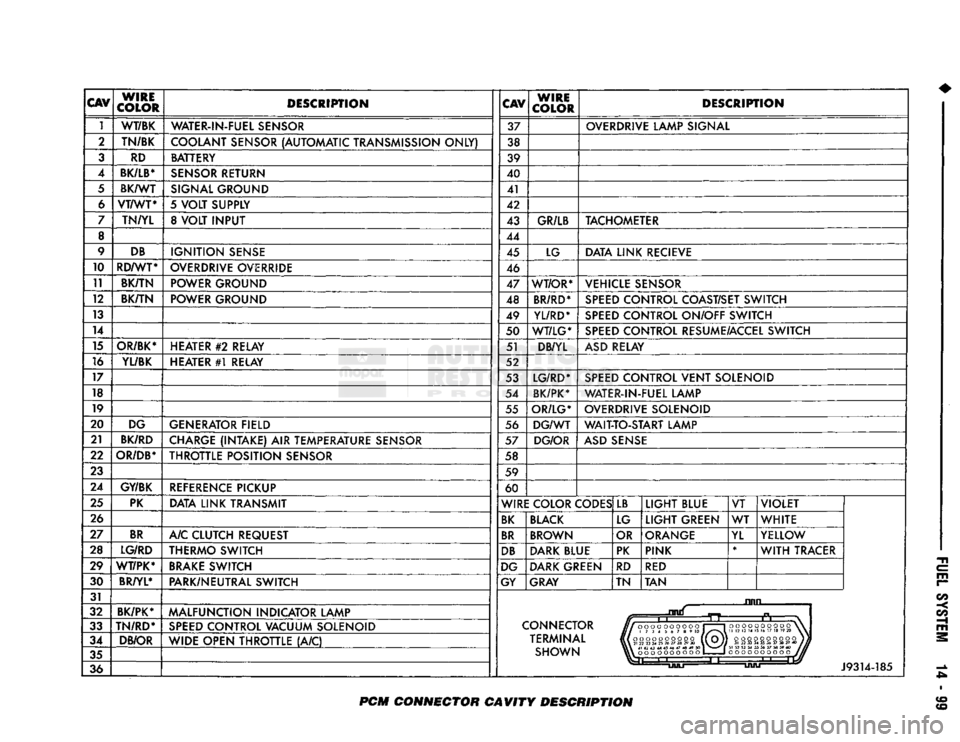
CAV
WIRE
COLOR DESCRIPTION
CAV
WIRE
COLOR DESCRIPTION
1 WT/BK
WATER-IN-FUEL SENSOR 37 OVERDRIVE LAMP SIGNAL
2 TN/BK
COOLANT SENSOR (AUTOMATIC TRANSMISSION ONLY) 38
3 RD BATTERY
39
4
BK/LB*
SENSOR RETURN 40
5 BK/WT
SIGNAL GROUND 41
6 VT/WT*
5 VOLT SUPPLY 42
7 TN/YL 8 VOLT INPUT 43 GR/LB TACHOMETER
8 44
9 DB
IGNITION SENSE 45 LG DATA LINK RECIEVE
10 RD/WT*
OVERDRIVE OVERRIDE 46
11 BK/TN POWER GROUND
47 WT/OR* VEHICLE SENSOR
12 BK/TN
POWER GROUND 48 BR/RD* SPEED CONTROL COAST/SET SWITCH
13 49 YL/RD* SPEED CONTROL ON/OFF SWITCH
14 50 WT/LG* SPEED CONTROL RESUME/ACCEL SWITCH
15 OR/BK* HEATER
#2
RELAY 51 DB/YL ASD RELAY
16 YL/BK HEATER #1 RELAY 52
17 53 LG/RD* SPEED CONTROL VENT SOLENOID
18 54 BK/PK* WATER-IN-FUEL LAMP
19 55 OR/LG* OVERDRIVE SOLENOID
20 DG GENERATOR FIELD 56 DG/WT WAIT-TO-START LAMP
21 BK/RD
CHARGE (INTAKE) AIR TEMPERATURE SENSOR 57 DG/OR ASD SENSE
22
OR/DB*
THROTTLE POSITION SENSOR 58
23 59
24 GY/BK
REFERENCE PICKUP 60
25 PK
DATA LINK TRANSMIT WIRE COLOR CODES LB
LIGHT BLUE VT VIOLET
26 BK BLACK LG LIGHT GREEN WT
WHITE
27 BR
A/C CLUTCH REQUEST BR BROWN OR ORANGE
YL YELLOW
28 LG/RD THERMO SWITCH DB DARK BLUE PK PINK *
WITH TRACER
29 WT/PK* BRAKE SWITCH DG DARK GREEN
RD RED
30 BR/YL*
PARK/NEUTRAL SWITCH GY GRAY TN TAN
31 ruin
32 BK/PK*
MALFUNCTION INDICATOR LAMP
n
33 TN/RD*
SPEED CONTROL VACUUM SOLENOID CONNECTOR
J//000OOOOOOO
1 1
HI
173456789
10 J/^"*\
Hi
oooooooooo (1 Oj]
VlX
21
22
23
24
25
26
27
28
29
30
\V~V//
oooooooooo
\
II
12 13
14 15
16 17 18
19 20
\
34 DB/OR
WIDE OPEN THROTTLE (A/C) TERMINAL
J//000OOOOOOO
1 1
HI
173456789
10 J/^"*\
Hi
oooooooooo (1 Oj]
VlX
21
22
23
24
25
26
27
28
29
30
\V~V//
oooooooooo)}
31
32 33 34 35 36 37 38 39 40
1JU
35 SHOWN \\\
41 42 43 44 45 46 47 48 49
SO
1
^m^^
|
oooooooooo
1
1
oooooooooo
J//
36
Li
J9314-185
PCM
CONNECTOR CAVITY DESCRIPTION