1993 DODGE TRUCK tow bar
[x] Cancel search: tow barPage 456 of 1502
•
REAR
WINDOW DEFOGGER
8N - 1
REAR
WINDOW
DEFOGGER
CONTENTS
page
REPAIR
PROCEDURES (GRID LINES,
TERMINALS,
AND
PIGTAILS)
3
GENERAL
INFORMATION
The electrically heated rear window defogger
is
available
on
Ramcharger with sunscreen glass only. The system consists
of a
rear window with
two
ver
tical
bus
bars
and a
series
of
electrically connected
grid lines baked
on the
inside surface. Circuit protection
for the
heated grid circuit
is
pro
vided
by a 18
gauge fusible link wire located
in the
engine compartment.
The
relay circuit
is
protected
by
a 20 amp
fuse, located
in the
fuse block. When
the
rear window defogger switch
is
placed
in
the
ON
position, current
is
directed
to
rear window
grid lines.
The
heated grid lines
in
turn heat
the
rear window
to
clear
the
surface
of fog or
snow.
CAUTION;
Grid lines
can be
damaged
or
scraped
off
with
sharp instruments. Care should
be
taken
in
page
SERVICE
PROCEDURES
4
TEST
PROCEDURES
1
cleaning
the
glass
or
removing foreign materials,
decals
or
stickers. Normal
glass
cleaning solvents
or
hot
water
used
with
rags
or
toweling
is
recom mended.
SYSTEM
DESCRIPTION CONTROL
SWITCH/TIMER
RELAY MODULE
The control switch
and
timer relay
are
integrated
into
a
single panel mounted assembly. Actuating
the
switch energizes
the
electronic timing circuit. This
allows current
to
flow through
the
grid system
for
approximately
10
minutes,
or
until either
the
control
switch
or
ignition
is
turned
off. An
indicating lamp
illuminates
a
lens inlaid
in the
control switch.
TEST PROCEDURES
SYSTEM
TEST
Electrically heated rear window defogger operation
can
be
checked in-vehicle
in the
following manner: (1) Turn
the
ignition
ON.
(2) Turn rear window defogger control switch
ON.
(3) Monitor vehicle voltmeter. With
the
control
switch
ON, a
distinct needle deflection should
be
noted. (4)
The
rear window defogger operation
can be
checked
by
feeling
the
glass.
A
distinct difference
in
temperature between
the
grid lines
and
adjacent clear glass
can be
detected
in 3 to 4
minutes
of
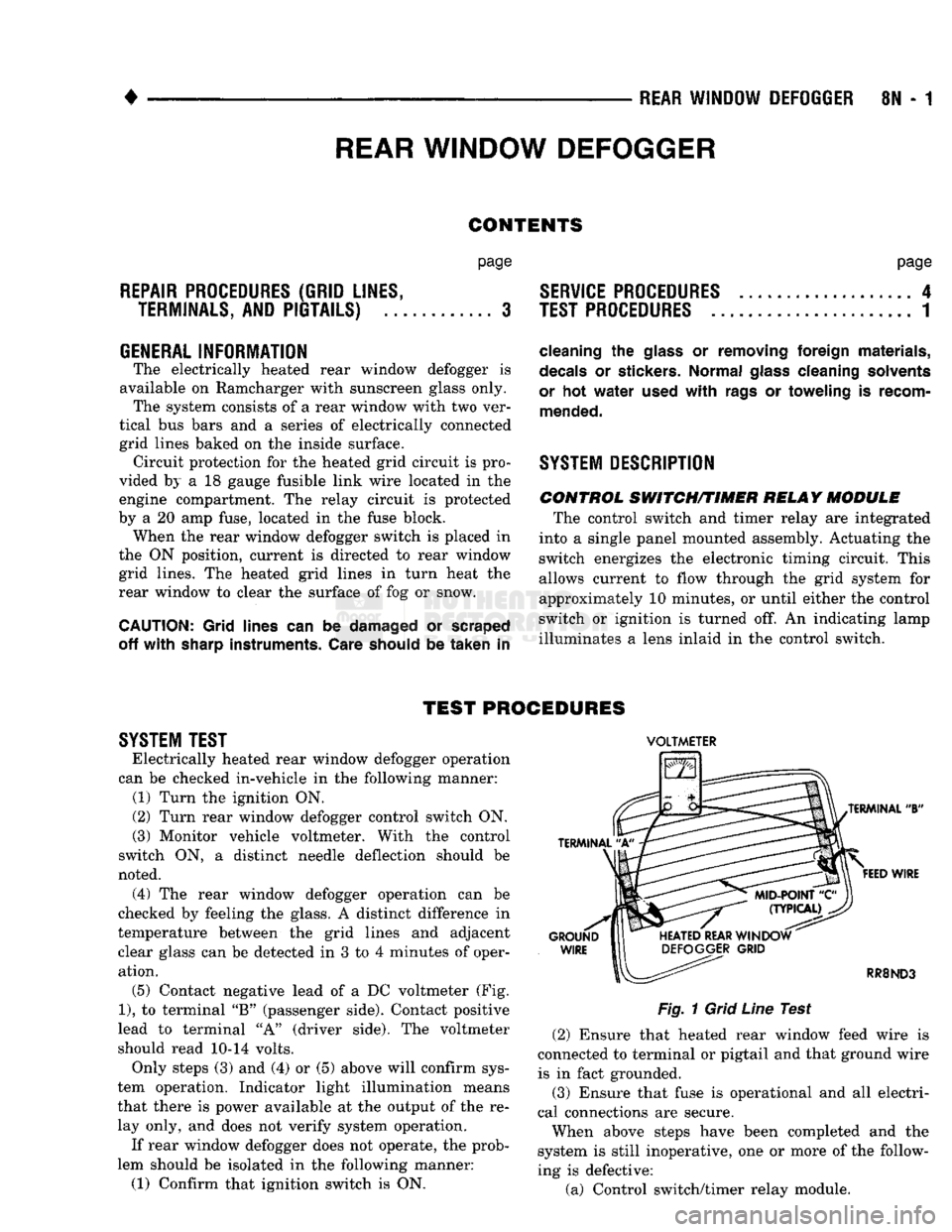
operation. (5) Contact negative lead
of a DC
voltmeter
(Fig.
1),
to
terminal
"B"
(passenger side). Contact positive
lead
to
terminal
"A"
(driver side).
The
voltmeter
should read
10-14
volts. Only steps
(3) and (4) or (5)
above will confirm sys
tem operation. Indicator light illumination means
that there
is
power available
at the
output
of the re
lay only,
and
does
not
verify system operation.
If rear window defogger does
not
operate,
the
prob
lem should
be
isolated
in the
following manner:
(1) Confirm that ignition switch
is ON.
VOLTMETER
Fig.
1
Grid
Line
Test (2) Ensure that heated rear window feed wire
is
connected
to
terminal
or
pigtail
and
that ground wire
is
in
fact grounded.
(3) Ensure that fuse
is
operational
and all
electri
cal connections
are
secure.
When above steps have been completed
and the
system
is
still inoperative,
one or
more
of the
follow
ing
is
defective:
(a) Control switch/timer relay module.
Page 457 of 1502
8N
- 2
REAR WINDOW DEFOGGER
• (b) Rear window grid lines (all grid lines would
have to be broken) or one of the feed wires are not
connected for the system to be inoperative.
The following paragraphs outline component check
out procedures.
If turning the switch ON produces severe voltmeter
deflection, the circuit should be closely checked for a shorting condition. If system operation has been verified but indicator
bulb does not light, check and replace bulb.
For detailed wiring information, refer to Group 8W
- Wiring Diagrams.
REAR
WINDOW GRID LINES TEST
Horizontal grid lines and vertical bus bar lines
printed and baked on inside surface of rear window glass (Fig. 1) comprise an electrical parallel circuit.
The electrically conductive lines are made of a silver- ceramic material. When baked onto glass they be
come bonded to the glass and are highly resistant to abrasion. It is possible, however, that a break may
exist or occur in an individual grid line resulting in
no current flow through the line. To detect breaks in
grid lines, the following procedure is required: (1) Turn ignition on and push control switch to
ON. Indicator light should come on. (2) Contact negative lead of a DC voltmeter, to
vertical bus bar connecting grid lines on passenger side of vehicle (point A of Fig. 1). Contact positive
lead of voltmeter, to vertical bus bar on driver side of
vehicle (point B of Fig. 1). Voltmeter should read 10-14 volts. (3) With negative lead of voltmeter, contact a good
body ground point. Voltage reading should not change. A different reading indicates a poor ground connection. (4) Connect negative lead of voltmeter to Point A
on passenger side bus bar and touch each grid line at
Mid-Point with positive lead. A reading of approxi mately 6 volts indicates a line is good. A reading of 0
volts indicates a break in line between Mid-Point C and Point B. A reading of 10-14 volts indicates a
break between Mid-Point C and ground Point A. Move toward break and voltage will change as soon as break is crossed.
CONTROL SWITCH/TIMER MODULE TEST
Control switch/timer relay module may be tested
in-vehicle or bench tested. In vehicle testing is ac
complished in the following manner: (1) Remove switch from instrument panel (refer to
Control Switch Replacement) and leave switch con
nector plugged in. (2) Turn ignition ON.
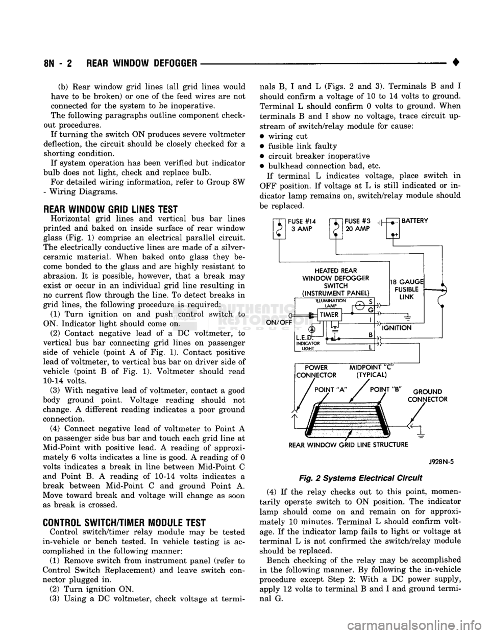
(3) Using a DC voltmeter, check voltage at termi nals B, I and L (Figs. 2 and 3). Terminals B and I
should confirm a voltage of 10 to 14 volts to ground.
Terminal L should confirm 0 volts to ground. When terminals B and I show no voltage, trace circuit up
stream of switch/relay module for cause:
• wiring cut
• fusible link faulty
• circuit breaker inoperative
• bulkhead connection bad, etc. If terminal L indicates voltage, place switch in
OFF position. If voltage at L is still indicated or in
dicator lamp remains on, switch/relay module should
be replaced.
"XI
FUSE
#14
rr~
P 3
AAAP
P
FUSE
#3
20
AAAP
BATTERY
HEATED
REAR
WINDOW
DEFOGGER
SWITCH
(INSTRUMENT
PANEL)
ON/OFF
ILLUMINATION
LAMP
fez TIMER
L.E.I
INDICATOR
LIGHT
-©-
18
GAUGE
FUSIBLE
LINK
IGNITION POWER
MIDPOINT
"C"
CONNECTOR (TYPICAL)
POINT
"A"
POINT
"B"
GROUND
CONNECTOR
REAR
WINDOW
GRID
LINE
STRUCTURE
Fig.
2
Systems
Electrical Circuit
J928N-5
(4) If the relay checks out to this point, momen
tarily operate switch to ON position. The indicator lamp should come on and remain on for approxi
mately 10 minutes. Terminal L should confirm volt
age.
If the indicator lamp fails to light or voltage at
terminal L is not confirmed the switch/relay module should be replaced.
Bench checking of the relay may be accomplished
in the following manner. By following the in-vehicle
procedure except Step 2: With a DC power supply, apply 12 volts to terminal B and I and ground termi
nal G.
Page 609 of 1502
9
- 4 ENGINES
•
RN861
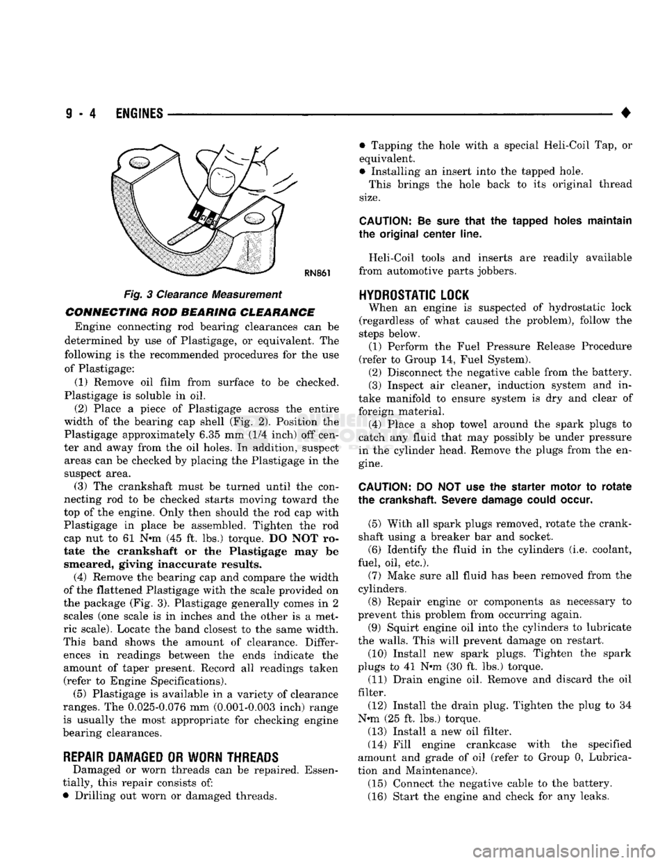
Fig. 3 Clearance Measurement
CONNECTING ROD BEARING CLEARANCE Engine connecting rod bearing clearances can be
determined by use of Plastigage, or equivalent. The
following is the recommended procedures for the use of Plastigage:
(1) Remove oil film from surface to be checked.
Plastigage is soluble in oil.
(2) Place a piece of Plastigage across the entire
width of the bearing cap shell (Fig. 2). Position the
Plastigage approximately 6.35 mm (1/4 inch) off cen
ter and away from the oil holes. In addition, suspect areas can be checked by placing the Plastigage in the
suspect area. (3) The crankshaft must be turned until the con
necting rod to be checked starts moving toward the
top of the engine. Only then should the rod cap with
Plastigage in place be assembled. Tighten the rod
cap nut to 61 Nnn (45 ft. lbs.) torque. DO NOT ro
tate the crankshaft or the Plastigage may be smeared, giving inaccurate results. (4) Remove the bearing cap and compare the width
of the flattened Plastigage with the scale provided on
the package (Fig. 3). Plastigage generally comes in 2 scales (one scale is in inches and the other is a met
ric scale). Locate the band closest to the same width.
This band shows the amount of clearance. Differ ences in readings between the ends indicate the
amount of taper present. Record all readings taken (refer to Engine Specifications). (5) Plastigage is available in a variety of clearance
ranges. The 0.025-0.076 mm (0.001-0.003 inch) range
is usually the most appropriate for checking engine
bearing clearances.
REPAIR DAMAGED OR WORN THREADS Damaged or worn threads can be repaired. Essen
tially, this repair consists of:
• Drilling out worn or damaged threads. • Tapping the hole with a special Heli-Coil Tap, or
equivalent.
• Installing an insert into the tapped hole.
This brings the hole back to its original thread
size.
CAUTION:
Be
sure
that
the tapped holes maintain
the original
center
line.
Heli-Coil tools and inserts are readily available
from automotive parts jobbers.
HYDROSTATIC
LOCK
When an engine is suspected of hydrostatic lock
(regardless of what caused the problem), follow the
steps below. (1) Perform the Fuel Pressure Release Procedure
(refer to Group 14, Fuel System). (2) Disconnect the negative cable from the battery.
(3) Inspect air cleaner, induction system and in
take manifold to ensure system is dry and clear of
foreign material. (4) Place a shop towel around the spark plugs to
catch any fluid that may possibly be under pressure
in the cylinder head. Remove the plugs from the en
gine.
CAUTION:
DO NOT use the starter motor to
rotate
the
crankshaft.
Severe
damage
could
occur.
(5) With all spark plugs removed, rotate the crank
shaft using a breaker bar and socket.
(6) Identify the fluid in the cylinders (i.e. coolant,
fuel, oil, etc.).
(7) Make sure all fluid has been removed from the
cylinders. (8) Repair engine or components as necessary to
prevent this problem from occurring again.
(9) Squirt engine oil into the cylinders to lubricate
the walls. This will prevent damage on restart.
(10) Install new spark plugs. Tighten the spark
plugs to 41 N#m (30 ft. lbs.) torque. (11) Drain engine oil. Remove and discard the oil
filter.
(12) Install the drain plug. Tighten the plug to 34
N-m (25 ft. lbs.) torque.
(13) Install a new oil filter.
(14) Fill engine crankcase with the specified
amount and grade of oil (refer to Group 0, Lubrica
tion and Maintenance). (15) Connect the negative cable to the battery.
(16) Start the engine and check for any leaks.
Page 663 of 1502
CAUTION:
Th© plunger and
tappet
bodies are not
interchangeable. The plunger and valve must al
ways
be
fitted
to the
original
body. It is advisable to
work
on one
tappet
at a
time
to avoid
mixing
of parts. Mixed
parts
are not
compatible.
DO NOT
dis
assemble
a
tappet
on a
dirty
work
bench,
DISASSEMBLE
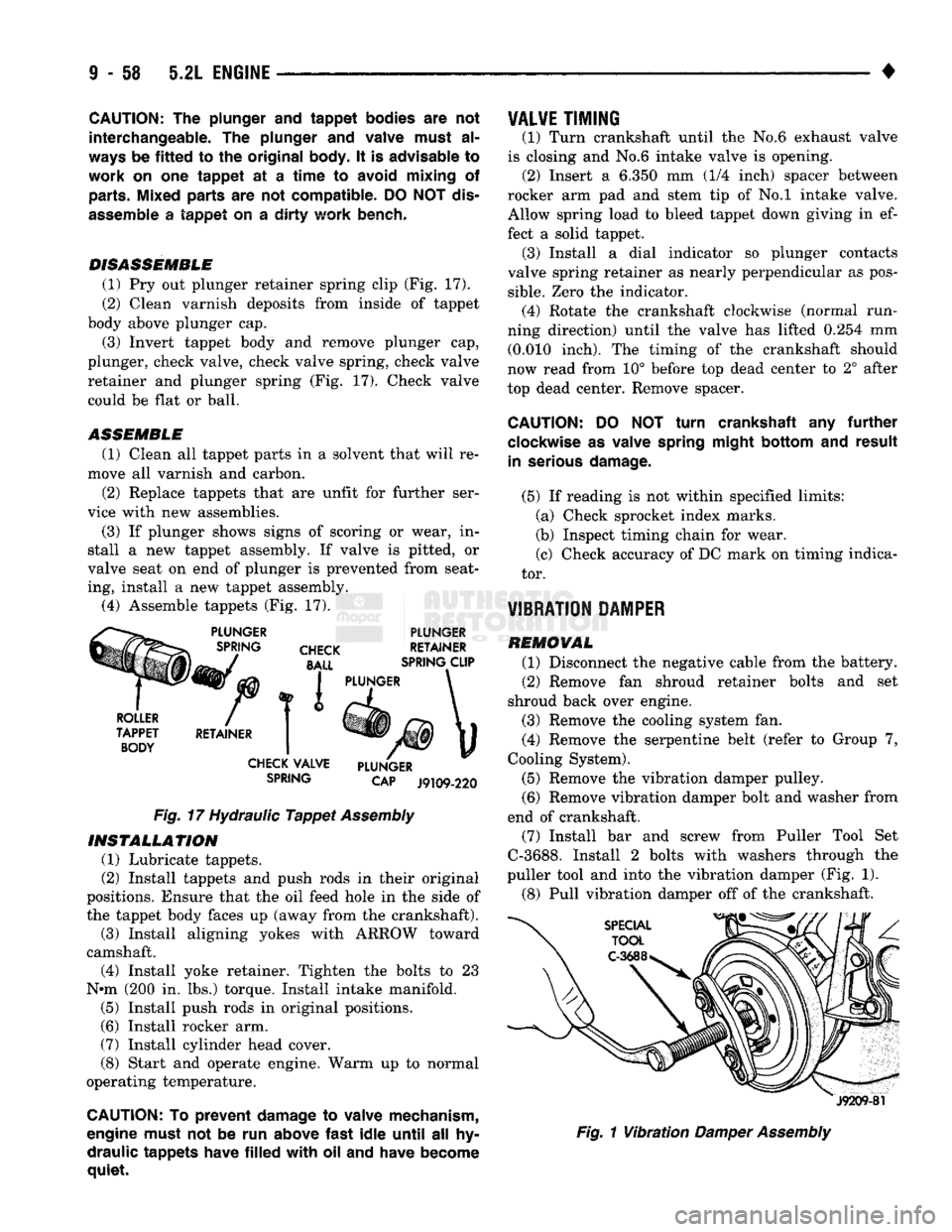
(1) Pry out plunger retainer spring clip (Fig. 17).
(2) Clean varnish deposits from inside of tappet
body above plunger cap.
(3) Invert tappet body and remove plunger cap,
plunger, check valve, check valve spring, check valve
retainer and plunger spring (Fig. 17). Check valve could be flat or ball.
ASSEMBLE
(1) Clean all tappet parts in a solvent that will re
move all varnish and carbon.
(2) Replace tappets that are unfit for further ser
vice with new assemblies.
(3) If plunger shows signs of scoring or wear, in
stall a new tappet assembly. If valve is pitted, or
valve seat on end of plunger is prevented from seat
ing, install a new tappet assembly. (4) Assemble tappets (Fig. 17).
PLUNGER
CHECK
BALL
PLUNGER
RETAINER
SPRING CLIP
ROLLER
TAPPET BODY RETAINER I PLUNGER
CHECK VALVE
SPRING PLUNGER
CAP
J9109-220
Fig.
17 Hydraulic
Tappet
Assembly
INSTALLATION
(1) Lubricate tappets.
(2) Install tappets and push rods in their original
positions. Ensure that the oil feed hole in the side of
the tappet body faces up (away from the crankshaft). (3) Install aligning yokes with ARROW toward
camshaft. (4) Install yoke retainer. Tighten the bolts to 23
N»m (200 in. lbs.) torque. Install intake manifold. (5) Install push rods in original positions.
(6) Install rocker arm.
(7) Install cylinder head cover.
(8) Start and operate engine. Warm up to normal
operating temperature.
CAUTION: To
prevent
damage to valve mechanism,
engine must not be run above
fast
idle
until
all hy
draulic
tappets
have
filled
with
oil and have become
quiet.
VALVE
TIMING
(1) Turn crankshaft until the No.6 exhaust valve
is closing and No.6 intake valve is opening. (2) Insert a 6.350 mm (1/4 inch) spacer between
rocker arm pad and stem tip of No.l intake valve. Allow spring load to bleed tappet down giving in ef
fect a solid tappet. (3) Install a dial indicator so plunger contacts
valve spring retainer as nearly perpendicular as pos
sible.
Zero the indicator. (4) Rotate the crankshaft clockwise (normal run
ning direction) until the valve has lifted 0.254 mm (0.010 inch). The timing of the crankshaft should
now read from 10° before top dead center to 2° after
top dead center. Remove spacer.
CAUTION:
DO NOT
turn
crankshaft any
further
clockwise as valve spring
might
bottom
and
result
in serious
damage.
(5) If reading is not within specified limits: (a) Check sprocket index marks.
(b) Inspect timing chain for wear.
(c) Check accuracy of DC mark on timing indica
tor.
VIBRATION DAMPER
REMOVAL (1) Disconnect the negative cable from the battery.
(2) Remove fan shroud retainer bolts and set
shroud back over engine.
(3) Remove the cooling system fan.
(4) Remove the serpentine belt (refer to Group 7,
Cooling System).
(5) Remove the vibration damper pulley. (6) Remove vibration damper bolt and washer from
end of crankshaft. (7) Install bar and screw from Puller Tool Set
C-3688. Install 2 bolts with washers through the
puller tool and into the vibration damper (Fig. 1).
(8) Pull vibration damper off of the crankshaft.
J9209-81
Fig.
1
Vibration
Damper
Assembly
Page 930 of 1502
•
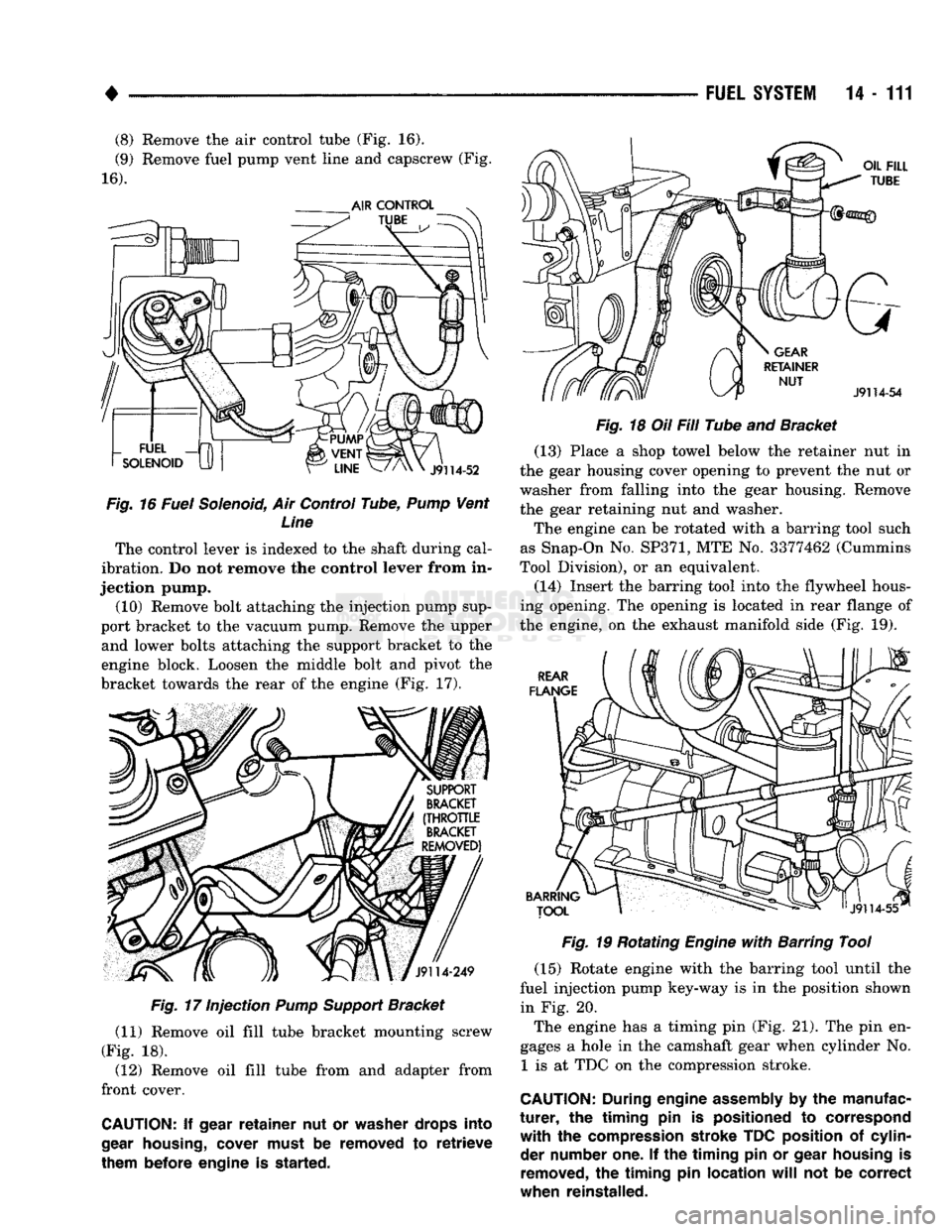
(8) Remove the air control tube (Fig. 16).
(9) Remove fuel pump vent line and capscrew (Fig.
16).
Fig.
16 Fuel Solenoid, Air Control Tube,
Pump
Vent Line
The control lever is indexed to the shaft during cal
ibration. Do not remove the control lever from in
jection pump. (10) Remove bolt attaching the injection pump sup
port bracket to the vacuum pump. Remove the upper and lower bolts attaching the support bracket to the
engine block. Loosen the middle bolt and pivot the
bracket towards the rear of the engine (Fig. 17).
Fig.
17 Injection
Pump
Support
Bracket
(11) Remove oil fill tube bracket mounting screw
(Fig. 18). (12) Remove oil fill tube from and adapter from
front cover.
CAUTION:
If
gear
retainer
nut or
washer drops into
gear
housing,
cover must
be
removed
to
retrieve
them before engine
is
started. FUEL
SYSTEM
14-111
Fig.
18 Oil Fill Tube and Bracket (13) Place a shop towel below the retainer nut in
the gear housing cover opening to prevent the nut or
washer from falling into the gear housing. Remove
the gear retaining nut and washer.
The engine can be rotated with a barring tool such
as Snap-On No.
SP371,
MTE No. 3377462 (Cummins
Tool Division), or an equivalent.
(14) Insert the barring tool into the flywheel hous
ing opening. The opening is located in rear flange of
the engine, on the exhaust manifold side (Fig. 19).
Fig.
19 Rotating
Engine
with
Barring Tool
(15) Rotate engine with the barring tool until the
fuel injection pump key-way is in the position shown in Fig. 20.
The engine has a timing pin (Fig. 21). The pin en
gages a hole in the camshaft gear when cylinder No. 1 is at TDC on the compression stroke.
CAUTION:
During
engine
assembly
by the
manufac
turer,
the
timing
pin is
positioned
to
correspond
with
the
compression stroke TDC position
of
cylin der number one.
If the
timing
pin or
gear housing
is
removed,
the
timing
pin
location
will
not be
correct
when reinstalled.
Page 932 of 1502
•
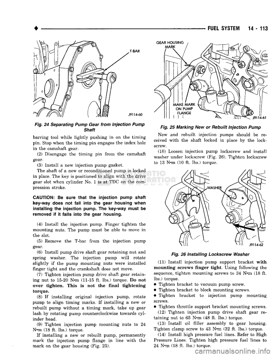
Fig.
24 Separating
Pump
Gear from injection
Pump
Shaft
barring tool while lightly pushing in on the timing
pin. Stop when the timing pin engages the index hole
in the camshaft gear.
(2) Disengage the timing pin from the camshaft
gear. (3) Install a new injection pump gasket.
The shaft of a new or reconditioned pump is locked
in place. The key is positioned to align with the drive
gear slot when cylinder No. 1 is at TDC on the com
pression stroke.
CAUTION:
Be
sure
that
the injection
pump
shaft
key-way
does
not
fall
into the
gear
housing
when
installing
the injection
pump.
The
key-way
must
be
removed
if it
falls
into the
gear
housing.
(4) Install the injection pump. Finger tighten the
mounting nuts. The pump must be able to move in
the slot.
(5) Remove the T-bar from the injection pump
gear.
(6) Install pump drive shaft gear retaining nut and
spring washer. The injection pump will rotate
slightly if the pump mounting nuts were installed
finger tight and the crankshaft does not move.
(7) Tighten injection pump drive shaft gear retain
ing nut to 15-20
Nth
(11-15 ft. lbs.) torque. Do not
over tighten. This is not the final tightening
torque.
(8) If installing original injection pump, rotate
pump to align timing marks. If installing a new or
rebuilt pump without a timing mark, take up gear lash by rotating pump counterclockwise towards cyl
inder head.
(9) Tighten injection pump mounting nuts to 24
Nnn (18 ft. lbs.) torque. If installing a new or rebuilt pump, permanently
mark the injection pump flange in line with the
mark on the gear housing (Fig. 25).
FUEL
SYSTEM
14 - 113
Fig.
25 Marking New or Rebuilt Injection
Pump
New and rebuilt injection pumps should be re
ceived with the shaft locked in place by the lock- screw.
(10) Loosen injection pump lockscrew and install
washer under lockscrew (Fig. 26). Tighten lockscrew to 13 Nnn (10 ft. lbs.) torque.
Fig.
26 Installing
Lockscrew
Washer
(11) Install injection pump support bracket with
mounting screws finger tight. Using following the sequence, tighten mounting screws to 24 Nnn (18 ft.
lbs.) torque.
• Tighten bracket to vacuum pump screw.
• Tighten bracket to block mounting screws. • Tighten bracket to injection pump mounting
screws.
• Tighten throttle support bracket mounting screws. (12) Tighten injection pump drive shaft gear re
taining nut to 65 N*m (48 ft. lbs.) torque.
(13) Install oil filler assembly to gear housing.
Tighten clamp screw to 43 Nnn (32 ft. lbs.) torque.
(14) Install high pressure fuel lines. Refer to High
Pressure Lines. Tighten high pressure fuel lines to 24 Nnn (18 ft. lbs.) torque.