1993 DODGE TRUCK flat tire
[x] Cancel search: flat tirePage 190 of 1502

•
BRAKES
i - 3 BRAKE DIAGNOSIS
INDEX
page
Brake
Warning Lights
3
Diagnosing
Brake Problems .................
4
Diagnosis
Procedures
3
Low
Vacuum
Switch—Diesel
Models
3
page
Master
Cylinder/Power Booster Test
5
Power
Booster
Check
Valve Test .............
6
Power
Booster
Vacuum
Test .................
6
Testing Diesel
Engine
Vacuum
Pump
Output
.... 6
DIAGNOSIS
PROCEDURES
Brake diagnosis involves determining
if the
prob
lem
is
related
to a
mechanical, hydraulic
or
vacuum
operated component.
A
preliminary check, road test
ing
and
component inspection
can all be
used
to de
termine
a
problem cause. Road testing will either verify proper brake opera
tion
or
confirm
the
existence
of a
problem. Compo nent inspection will,
in
most cases, identify
the
actual part causing
a
problem. The first diagnosis step
is the
preliminary check. This
involves inspecting fluid level, parking brake action,
wheel
and
tire condition, checking
for
obvious leaks
or
component damage
and
testing brake pedal response. A road test will confirm
the
existence
of a
problem.
Final diagnosis procedure involves road test analysis and
a
visual inspection
of
brake components.
BRAKE
WARNING LIGHTS
The
red
brake warning light
is
connected
to the
parking brake switch
and to the
pressure differential switch
in the
combination valve. The
red
light will illuminate when
the
parking
brakes
are
applied
or
when
a
fluid pressure drop
oc
curs
in the
front
or
rear brake circuit.
The
light will
also illuminate
for
approximately
2-4
seconds
at en
gine start
up.
This
is a
self test feature designed
to
check bulb
and
circuit operation each time
the en
gine
is
started. The amber antilock light
is
connected
to the
anti-
lock rear brake hydraulic valve.
The
light will illu
minate
if a
fault occurs within
the
antilock system.
LOW VACUUM SWITCH-DIESEL MODELS
On diesel models,
the red
brake warning light
is
also
used
to
alert
the
driver
of a low
brake booster vacuum
condition.
The
warning light
is in
circuit with
a
vacuum
warning switch mounted
on the
driver side fender
panel.
The
vacuum side
of the
switch
is
connected
to the
power brake booster.
The
electrical side
of the
switch
is
connected
to the
brake warning light. The
low
vacuum switch monitors booster vacuum
level whenever
the
engine
is
running.
If
booster vac
uum falls below
8.5
inches vacuum
for a
minimum
of
10 seconds,
the
switch completes
the
circuit
to the
warning light causing
it to
illuminate.
The
warning light
is
designed
to
differentiate between
a low
vac
uum condition
and a
hydraulic circuit fault.
PRELIMINARY
BRAKE CHECK
(1) Check condition
of
tires
and
wheels. Damaged
wheels
and
worn, damaged,
or
underinflated tires
can
cause pull, shudder, tramp,
and a
condition similar
to
grab.
(2)
If
complaint
was
based
on
noise when braking,
check suspension components. Jounce front
and
rear
of
vehicle
and
listen
for
noise that might
be
caused
by
loose, worn
or
damaged suspension
or
steering compo
nents.
(3) Inspect brake fluid level
and
condition. Note
that
the
front disc brake reservoir fluid level will drop
in
proportion
to
normal lining wear. Also note
that brake fluid tends
to
darken over time. This
is normal
and
should
not be
mistaken
for
con
tamination.
If the
fluid
is
still clear
and
free
of
foreign material,
it is OK.
(a)
If
fluid level
is
abnormally
low,
look
for
evi
dence
of
leaks
at
calipers, wheel cylinders, brake-
lines
and
master cylinder.
(b)
If
fluid appears contaminated, drain
out a
sample.
If
fluid
is
separated into layers,
or
obvi
ously contains
oil or a
substance other than brake
fluid,
the
system seals
and
cups will have
to be re
placed
and the
hydraulic system flushed.
(4) Check parking brake operation. Verify free
movement
and
full release
of
cables
and
pedal. Also
note
if
vehicle
was
being operated with parking
brake partially applied.
(5) Check brake pedal operation. Verify that pedal
does
not
bind
and has
adequate free play.
If
pedal
lacks free play, check pedal
and
power booster
for be
ing loose
or for
bind condition.
Do not
road test until
condition
is
corrected.
(6)
If
components checked appear
OK,
road test
the
vehicle.
ROAD
TESTING (1)
If
complaint involved
low
brake pedal, pump
the pedal
and
note
if the
pedal comes back
up to
nor mal height.
(2) Check brake pedal response with transmission
in Neutral
and
engine running. Pedal should remain
firm under steady foot pressure.
Page 192 of 1502

•
BRAKES
5 - 5 Disc brake rotors with excessive lateral runout or
thickness variation, or out of round brake drums are
the primary causes of pulsation. Other causes are loose
wheel bearings or calipers and worn, damaged tires.
PULL A
front pull condition could be the result of con
taminated lining in one caliper, seized caliper piston,
binding caliper, loose caliper, loose or corroded slide
pins,
improper brakeshoes, or a damaged rotor.
A worn, damaged wheel bearing or suspension compo
nent are further causes of pull. A damaged front tire (bruised, ply separation) can also cause pull.
A common and frequently misdiagnosed pull condi
tion is where direction of pull changes after a few
stops.
The cause is a combination of brake drag fol
lowed by fade at one of the brake units.
As the dragging brake overheats, efficiency is so
reduced that fade occurs. Since the opposite brake
unit is still functioning normally, its braking effect is
magnified. This causes pull to switch direction in fa
vor of the normally functioning brake unit.
When diagnosing a change in pull condition, re
member that pull will return to the original direction
if the dragging brake unit is allowed to cool down (and is not seriously damaged).
REAR BRAKE GRAB
OR
PULL
Rear grab or pull is usually caused by an improperly
adjusted or seized parking brake cable, contaminated
lining, bent or binding shoes and support plates, or im
properly assembled components. This is particularly
true when only one rear wheel is involved. However,
when both rear wheels are affected, the master cylinder or proportioning valve could be at fault.
BRAKES
DO NOT
HOLD
AFTER
DRIVING
THROUGH
DEEP
WATER
PUDDLES
This condition is generally caused by water soaked
lining. If the lining is only wet, it can be dried by driv
ing with the brakes very lightly applied for a few min
utes.
However, if the lining is thoroughly wet and dirty,
disassembly and cleaning will be necessary.
BRAKE NOISE
Squeak/Squeal
Brake squeak or squeal may be due to linings that
are wet or contaminated with brake fluid, grease, or oil. Glazed linings and rotors with hard spots can also con
tribute to squeak. Dirt and foreign material embedded in the brake lining can also cause squeak/squeal.
A very loud squeak or squeal is frequently a sign of
severely worn brake lining. If the lining has worn
through to the brakeshoes in spots, metal-to-metal con
tact occurs. If the condition is allowed to continue, ro tors can become so scored that replacement is necessary.
Thump/Clunk
Thumping or clunk noises during braking are fre
quently not caused by brake components. In many
cases,
such noises are caused by loose or damaged steering, suspension, or engine components. How
ever, calipers that bind on the slide pins, or slide sur
faces,
can generate a thump or clunk noise. Worn
out, improperly adjusted, or improperly assembled
rear brakeshoes can also produce a thump noise.
Chatter
Brake chatter is usually caused by loose or worn
components, or glazed/burnt lining. Rotors with hard
spots can also contribute to chatter. Additional
causes of chatter are out of tolerance rotors, brake
lining not securely attached to the shoes, loose wheel
bearings and contaminated brake lining.
Brakelining Contamination Brakelining contamination is usually a product of
leaking calipers or wheel cylinders, driving through
deep water puddles, or lining that has become cov
ered with grease and grit during repair.
Wheel and
Tire
Problems Some conditions attributed to brake components
may actually be caused by a wheel or tire problem.
A damaged wheel can cause shudder, vibration and
pull. A worn or damaged tire can also cause pull.
Severely worn tires with very little tread left can
produce a grab-like condition as the tire loses and re covers traction. Flat-spotted tires can cause vibration and wheel
tramp and generate shudder during brake operation. A tire with internal damage such as a severe
bruise or ply separation can cause pull and vibration.
MASTER
CYLINDER/POWER BOOSTER TEST
(1) Start engine and check booster vacuum hose
connections. Hissing noise indicates a vacuum leak. Correct any leaks before proceeding. (2) Stop engine and shift transmission into Neu
tral (3) Pump brake pedal until all vacuum reserve in
booster is depleted. (4) Press and hold brake pedal under light foot
pressure. (a) If pedal holds firm, proceed to step (5).
(b) If pedal does not hold firm and falls away,
master cylinder is faulty (internal leakage). (5) Start engine and note pedal action. (a) If pedal falls away slightly under light foot
pressure then holds firm, proceed to step (6). (b) If pedal is effort is high, or no pedal action is
discernible, power booster or vacuum check valve is
faulty. Install known good check valve and repeat steps (2) through (5).
Page 242 of 1502
•
BRAKES
5 - 55 Inspect the cylinder bore. Light discoloration and
dark stains in the bore are normal and will not im
pair cylinder operation. If desired, the bore can be lightly polished but only with crocus cloth. Replace
the cylinder if the bore is scored, pitted or heavily corroded. Honing the bore to restore the surface is not recommended.
Inspect the cylinder pistons. The piston surfaces
should be smooth and free of scratches, scoring and
corrosion. Replace the pistons if worn, scored, or cor
roded. Do attempt to restore the surface by sanding or polishing.
Discard the old piston cups and the spring and ex
pander. These parts are not reusable. The original
dust boots may be reused but only if they are in good condition.
ASSEMBLING
WHEEL CYLINDER
(1) Lubricate wheel cylinder bore, pistons, piston
cups and spring and expander with ^clean brake fluid. (2) Install first piston in cylinder bore. Then in
stall cup in bore and against piston. Be sure lip of
piston cup is facing inward (toward spring and
expander) and flat side is against piston.
(3) Install spring and expanders followed by re
maining piston cup and piston.
(4) Install boots on each end of cylinder and insert
push rods in boots.
(5)
Install cylinder bleed screw.
WHEEL
CYLINDER INSTALLATION
(1) Start brakeline into cylinder.
(2) Position cylinder on support plate and install
cylinder attaching bolts. (3) Tighten brakeline fitting and cylinder attach
ing bolts. (4) Install anchor pin bushing, cam plate, adjuster
cable, parking brake lever, spring washer and anchor
bolt and nut.
(5) Install brakeshoes and brake drum as described
in this section. (6) Install axle shaft.
(7) Install wheel and tire.
(8) Remove supports and lower vehicle.
SUPPORT
PLATE REMOVAL
(1) Raise and support vehicle.
(2) Remove wheel and tire.
(3) Remove axle shaft.
(4) Remove brake drum, brake shoes and wheel
cylinder as described in this section. (5) Remove bolts/nuts attaching support plate to
axle and remove support plate.
SUPPORT PLATE INSTALLATION
(1) Transfer wheel cylinder and parking brake le
ver components to replacement support plate. (2) Position support plate on axle and install at
taching bolts/nuts. (3) Lubricate shoe contact surfaces of support plate
with Mopar multi-purpose, or high temperature bear ing grease. (4) Install brakeshoes. Adjust shoes to drum with
brake gauge. (5) Install brake drum.
(6) Install axle shaft.
(7) Install wheel and tire.
(8) Remove supports and lower vehicle.
Page 446 of 1502

•
LAMPS
8L - 3
EXTERIOR
LAMPS
SERWICE PROCEDURES
INDEX
page
Cargo
Lamp
7
Clearance Lamps
for
Dual Wheel Model
........
5
Daytime Running
Light
Module (Canada Only)
... 8
Front
Park
and
Turn Signal Lamp Bulb
4
Headlamp
Adjustment
Using
Alignment
Screen
... 3
Headlamp
Alignment
3
Headlamp
Alignment
Preparation
3
page
Headlamp Switch
4
License
Lamp
............................
7
Sealed
Beam Replacement
4
Side
Marker Lamp
and
Bulb
. 5
Tail,
Stop, Turn Signal, Rear Side Marker
and
Back-Up
Lamps
5
Underhood Lamp
8
HEADLAMP
ALIGNMENT
Headlamps
can be
aligned using
the
screen method
provided
in
this section. Alignment Tool C4466-A
or
equivalent
can
also
be
used. Refer
to
instructions
provided with
the
tool
for
proper procedures.
The
preferred headlamp alignment setting
is 0 for
the left/right adjustment
and
1" down
for the up/
down adjustment.
HEADLAMP
ALIGNMENT PREPARATION
(1) Verify headlamp dimmer switch
and
high beam
indicator operation. (2) Correct defective components that could hinder
proper headlamp alignment. (3) Verify proper tire inflation. (4) Clean headlamp lenses.
(5) Verify that luggage area
is not
heavily loaded.
(6) Fuel tank should
be
FULL.
Add 2.94 kg (6.5
lbs.)
of
weight over
the
fuel tank
for
each estimated
gallon
of
missing fuel.
HEADLAMP
ADJUSTMENT USING ALIGNMENT
SCREEN
ALIGNMENT SCREEN PREPARATION (1) Position vehicle
on a
level surface perpendicu
lar
to a
flat wall
7.62
meters
(25 ft)
away from front
of headlamp lens.
(2)
If
necessary, tape
a
line
on the
floor
7.62
meters
(25 ft)
away from
and
parallel
to the
wall.
CENTER
OF
VEHICLE
TO
CENTER
OF
HEADLAMP
LENS
VEHICLE
CENTERLINE" LOW BEAM
HOT
SPOT AREA FLOOR
TO
CENTER
OF
HEADLAMP
LENS
PREFERRED
HOT SPOT
LOCATION
7.62
METERS
(25
FEET)
FRONT
OF
HEADLAMP
938L-25X
Fig.
1 Headlamp
Alignment
Screen
—Typical
Page 608 of 1502
•
ENGINES
9 - 3
(3) Honing
should be
done
by moving the
hone
up
and down
fast
enough
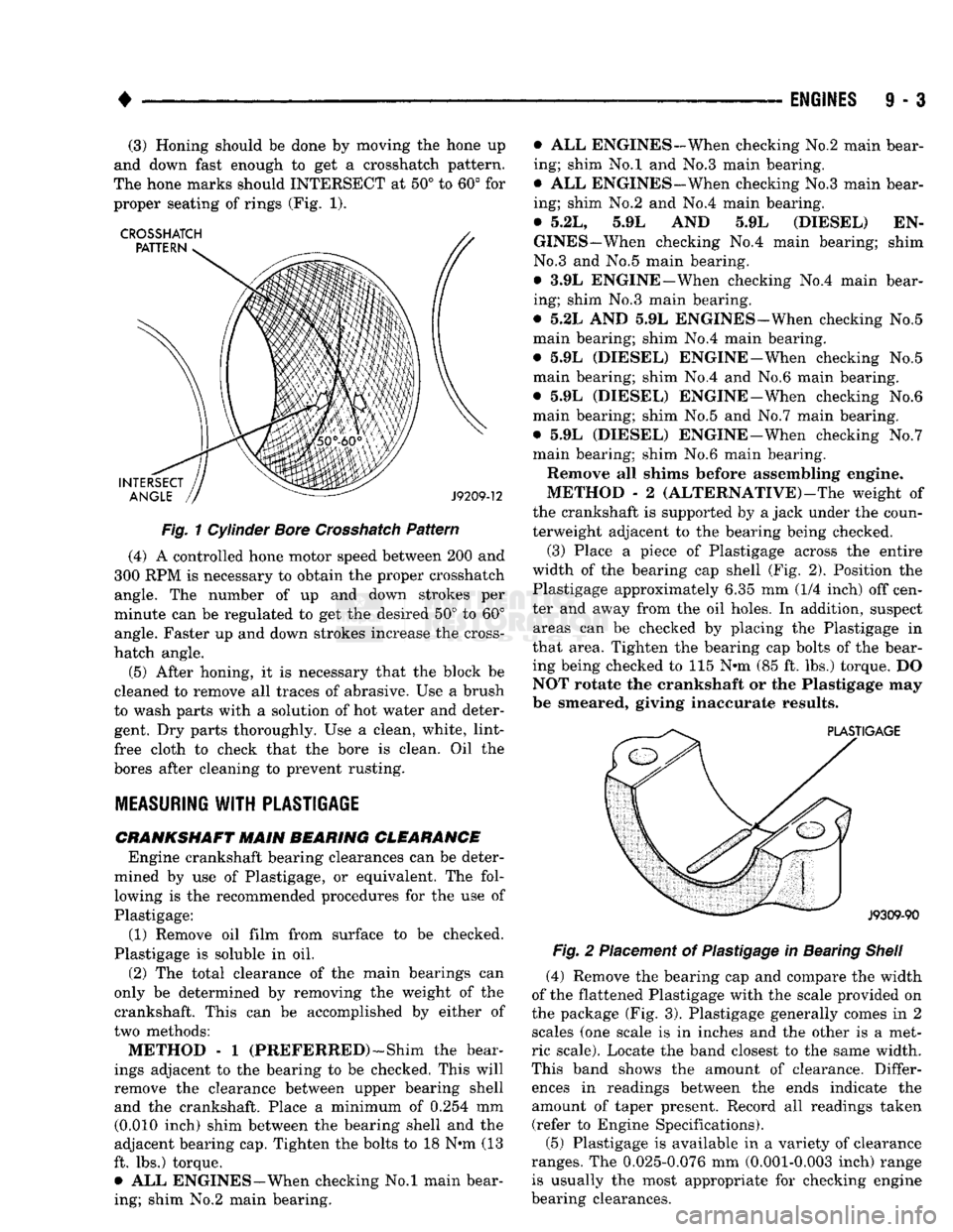
to get a Crosshatch pattern.
The hone
marks should
INTERSECT
at 50° to 60° for
proper seating
of
rings (Fig.
1).
Fig.
1
Cylinder
Bore
Crosshatch
Pattern
(4)
A
controlled hone motor speed between
200 and
300
RPM is
necessary
to
obtain
the
proper Crosshatch angle.
The
number
of up and
down strokes
per
minute
can be
regulated
to get the
desired
50° to 60°
angle. Faster
up and
down strokes increase
the
cross-
hatch angle.
(5) After honing,
it is
necessary that
the
block
be
cleaned
to
remove
all
traces
of
abrasive.
Use a
brush
to wash parts with
a
solution
of hot
water
and
deter gent.
Dry
parts thoroughly.
Use a
clean, white, lint-
free cloth
to
check that
the
bore
is
clean.
Oil the
bores after cleaning
to
prevent rusting.
MEASURING
WITH
PLASTIGAGE
CRANKSHAFT
MAIN BEARING CLEARANCE Engine crankshaft bearing clearances
can be
deter
mined
by use of
Plastigage,
or
equivalent.
The
fol lowing
is the
recommended procedures
for the use of
Plastigage:
(1) Remove
oil
film from surface
to be
checked.
Plastigage
is
soluble
in oil.
(2)
The
total clearance
of the
main bearings
can
only
be
determined
by
removing
the
weight
of the
crankshaft. This
can be
accomplished
by
either
of
two methods:
METHOD - 1
(PREFERRED)—Shim
the
bear
ings adjacent
to the
bearing
to be
checked. This will
remove
the
clearance between upper bearing shell and
the
crankshaft. Place
a
minimum
of
0.254
mm
(0.010 inch) shim between
the
bearing shell
and the
adjacent bearing cap. Tighten
the
bolts
to 18 N*m (13
ft.
lbs.)
torque. •
ALL
ENGINES—When checking
No.l
main bear
ing; shim
No.2
main bearing. •
ALL
ENGINES-When checking
No.2
main bear
ing; shim
No.l and No.3
main bearing.
•
ALL
ENGINES-When checking No.3 main bear
ing; shim
No.2 and No.4
main bearing.
•
5.2L, 5.9L AND 5.9L
(DIESEL)
EN
GINES—When checking
No.4
main bearing; shim
No.3
and No.5
main bearing.
•
3.9L
ENGINE—When checking
No.4
main bear
ing; shim
No.3
main bearing.
•
5.2L AND 5.9L
ENGINES—When checking
No.5
main bearing; shim
No.4
main bearing.
•
5.9L
(DIESEL) ENGINE-When checking
No.5
main bearing; shim
No.4 and No.6
main bearing.
•
5.9L
(DIESEL) ENGINE-When checking
No.6
main bearing; shim
No.5 and No.7
main bearing.
•
5.9L
(DIESEL) ENGINE-When checking
No.7
main bearing; shim
No.6
main bearing.
Remove
all
shims before assembling engine.
METHOD
- 2
(ALTERNATIVE)—The weight
of
the crankshaft
is
supported
by a
jack under
the
coun
terweight adjacent
to the
bearing being checked.
(3) Place
a
piece
of
Plastigage across
the
entire
width
of the
bearing
cap
shell
(Fig. 2).
Position
the
Plastigage approximately
6.35 mm (1/4
inch)
off
cen
ter
and
away from
the oil
holes.
In
addition, suspect areas
can be
checked
by
placing
the
Plastigage
in
that area. Tighten
the
bearing
cap
bolts
of the
bear
ing being checked
to 115 N»m (85 ft. lbs.)
torque.
DO
NOT rotate
the
crankshaft
or the
Plastigage
may
be smeared, giving inaccurate results.
Fig.
2
Placement
of
Plastigage
in
Bearing
Shell
(4) Remove
the
bearing
cap and
compare
the
width
of
the
flattened Plastigage with
the
scale provided
on
the package
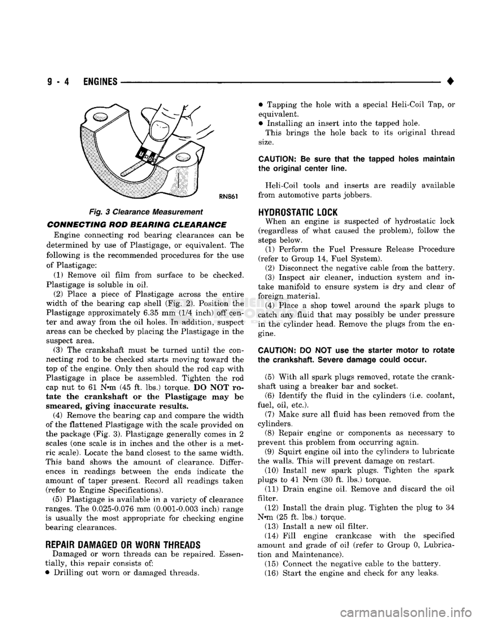
(Fig. 3).
Plastigage generally comes
in 2
scales
(one
scale
is in
inches
and the
other
is a
met
ric scale). Locate
the
band closest
to the
same width.
This band shows
the
amount
of
clearance. Differ ences
in
readings between
the
ends indicate
the
amount
of
taper present. Record
all
readings taken (refer
to
Engine Specifications).
(5) Plastigage
is
available
in a
variety
of
clearance
ranges.
The
0.025-0.076
mm
(0.001-0.003 inch) range is usually
the
most appropriate
for
checking engine
bearing clearances.
Page 609 of 1502
9
- 4 ENGINES
•
RN861
Fig. 3 Clearance Measurement
CONNECTING ROD BEARING CLEARANCE Engine connecting rod bearing clearances can be
determined by use of Plastigage, or equivalent. The
following is the recommended procedures for the use of Plastigage:
(1) Remove oil film from surface to be checked.
Plastigage is soluble in oil.
(2) Place a piece of Plastigage across the entire
width of the bearing cap shell (Fig. 2). Position the
Plastigage approximately 6.35 mm (1/4 inch) off cen
ter and away from the oil holes. In addition, suspect areas can be checked by placing the Plastigage in the
suspect area. (3) The crankshaft must be turned until the con
necting rod to be checked starts moving toward the
top of the engine. Only then should the rod cap with
Plastigage in place be assembled. Tighten the rod
cap nut to 61 Nnn (45 ft. lbs.) torque. DO NOT ro
tate the crankshaft or the Plastigage may be smeared, giving inaccurate results. (4) Remove the bearing cap and compare the width
of the flattened Plastigage with the scale provided on
the package (Fig. 3). Plastigage generally comes in 2 scales (one scale is in inches and the other is a met
ric scale). Locate the band closest to the same width.
This band shows the amount of clearance. Differ ences in readings between the ends indicate the
amount of taper present. Record all readings taken (refer to Engine Specifications). (5) Plastigage is available in a variety of clearance
ranges. The 0.025-0.076 mm (0.001-0.003 inch) range
is usually the most appropriate for checking engine
bearing clearances.
REPAIR DAMAGED OR WORN THREADS Damaged or worn threads can be repaired. Essen
tially, this repair consists of:
• Drilling out worn or damaged threads. • Tapping the hole with a special Heli-Coil Tap, or
equivalent.
• Installing an insert into the tapped hole.
This brings the hole back to its original thread
size.
CAUTION:
Be
sure
that
the tapped holes maintain
the original
center
line.
Heli-Coil tools and inserts are readily available
from automotive parts jobbers.
HYDROSTATIC
LOCK
When an engine is suspected of hydrostatic lock
(regardless of what caused the problem), follow the
steps below. (1) Perform the Fuel Pressure Release Procedure
(refer to Group 14, Fuel System). (2) Disconnect the negative cable from the battery.
(3) Inspect air cleaner, induction system and in
take manifold to ensure system is dry and clear of
foreign material. (4) Place a shop towel around the spark plugs to
catch any fluid that may possibly be under pressure
in the cylinder head. Remove the plugs from the en
gine.
CAUTION:
DO NOT use the starter motor to
rotate
the
crankshaft.
Severe
damage
could
occur.
(5) With all spark plugs removed, rotate the crank
shaft using a breaker bar and socket.
(6) Identify the fluid in the cylinders (i.e. coolant,
fuel, oil, etc.).
(7) Make sure all fluid has been removed from the
cylinders. (8) Repair engine or components as necessary to
prevent this problem from occurring again.
(9) Squirt engine oil into the cylinders to lubricate
the walls. This will prevent damage on restart.
(10) Install new spark plugs. Tighten the spark
plugs to 41 N#m (30 ft. lbs.) torque. (11) Drain engine oil. Remove and discard the oil
filter.
(12) Install the drain plug. Tighten the plug to 34
N-m (25 ft. lbs.) torque.
(13) Install a new oil filter.
(14) Fill engine crankcase with the specified
amount and grade of oil (refer to Group 0, Lubrica
tion and Maintenance). (15) Connect the negative cable to the battery.
(16) Start the engine and check for any leaks.
Page 812 of 1502
FRAME
AND
BUMPERS
13 - 25
FUNCTION
The frame is the foundation and the structural cen
ter of the vehicle. The primary function of a frame is
to provide support and attachment locations: • For all the chassis/drivetrain components
• For the cab/body
• For the vehicle payload While limiting deflections and twisting of the
frame members. The frame maintains the correct relationship and
alignment of the powertrain. This relationship and
alignment ensures normal operation of the attached
units.
CONSTRUCTION MATERIAL High-strength, carbon steel with a minimum yield
strength of 32,000 psi is used to construct frame side
rails.
A frame made of 32,000 psi minimum yield
strength steel has, in reality, a range of 32,000 to
44,000 psi yield strength.
For 4WD vehicle applications, the frame side rails
reinforcements are constructed of the same high- strength, carbon steel as the side rails.
BENDING RESISTANCE A frame reacts to its load and the road surface de
viations by deflecting and twisting. The primary de
flecting frame members are the side rails. Resistance
to frame twist is provided by the crossmembers.
FRAME
INSPECTION/MEASUREMENTS
INSPECTION Inspect the frame members for visible damage and
metal deformations. Inspect all riveted, bolted and
welded connections for looseness and/or missing hardware. All damaged areas must be repaired and/or the
frame members replaced, as necessary.
MEASUREMENTS Measure the frame for mis-alignment with the cab/
body and cargo box attached to the frame. Figures 7, 8, 9 provide the frame alignment reference dimen
sions.
The following information applies to all measure
ments.
(1) Place the vehicle on a level surface.
(2) If the vehicle is loaded, verify the vehicle does
not exceed the gross vehicle weight rating (GVWR).
Verify the load is distributed in the vehicle as evenly as possible. For better measurement results, remove
the cargo/payload from the vehicle.
(3) Measure the tire inflation pressures. Adjust as
necessary.
HORIZONTAL/DIAGONAL
FRAME MEASUREMENTS
Determine the frame horizontal, according to the
following procedure.
(1) Select several reference points along one frame
side rail, preferably at the crossmember junctions.
(2) Transfer these reference points to the surface/
floor. Paper sheets can be attached to the surface be low the reference points.
(3) Locate the same reference points on the other
frame side rail. Transfer them to the surface/floor.
(4) Move the vehicle away. Measure between all
the reference points diagonally from and parallel to
the side rails (Fig. 10). The corresponding measure ments should not differ by more than 6 mm (1/4 in).
(5)
Measure the distance between the two front
reference points. Measure the distance between the
two rear reference points. Divide each distance in
half and indicate the two half-way points on the sur
face/floor. Designate the front point as 1 and the rear
point as 2 (Fig. 10).
(6) Place a chalk-line between points 1 and 2 (Fig.
10) and snap the string.
(7) Determine how close the center line is to the
diagonal intersection points in Figure 10.
(8) The marks on the floor will show the amount of
frame misalignment.
(9) The reference point transferred from one side
rail should be within 3 mm (1/8 in) of the opposite
reference point.
(10) Frame bow to the side should not exceed 3
mm per 2540 mm (1/8 inch per 100 inches) in frame
length.
(11) The overall width of the frame should not
vary more than 3 mm (1/8 in). (12) Repeat steps (1) through (11) after straighten
ing the frame.
Refer to Figures 7, 8, and 9 for frame horizon
tal alignment reference dimensions.
TWIST
AND PARALLEL FRAME MEASUREMENTS
Determine the amount of frame twist using the fol
lowing procedure.
(1) Mark the vertical reference points under the
frame side rails at 305-mm (12-in) intervals. Start at
the rear frame crossmember.
(2) Measure the distance up from a level surface/
floor to each corresponding reference point. (3) The distance to a reference point under one
side rail should be a maximum of 3 mm (1/8 in)
dif
ference than the opposite side rail.
Refer to Figures 7, 8 and 9 for frame vertical
alignment reference dimensions.
Page 950 of 1502
•
PROPELLER
SHAFTS
16-5 A propeller shaft is properly phased when the yoke
ends are on the same plane or in line. A twisted
shaft will throw the yokes out of phase and cause a
noticeable vibration.
When taking universal joint angle measurements
or checking phasing with two piece shafts, consider
each shaft separately. On 4WD vehicles, the front shaft input (pinion shaft) angle has priority over the
caster angle.
Ideally the driveline system should have:
•
Angles that are in equal or opposite within 1
degree of each other
•
Have a 3 degree maximum operating angle
•
Have at least a 1/2 degree continuous operat
ing (propeller shaft) angle Engine speed (R.P.M.) is the main factor though in
determining maximum allowable operating angles.
As a guide to maximum normal operating angles re
fer to the chart listed (Fig. 4).
PROPELLER
SHAFT
MAX*
NORMAL
R«P*JVi*
OPERATING
ANGLES
5000
3°
4500
3°
4000
4°
3500
5°
3000
5°
2500
7°
2000
8°
1500 11°
J9316-4
Fig.
4 Maximum
Angles
and
R.P.M.
INSPECTION
Before measuring universal joint angles, the
following must done.
•
Inflate all tires to correct pressure.
•
Check angles in the same loaded or unloaded condition as when the vibration occurred. Prop
shaft angles will change according to the
amount of load in the vehicle. Always check an
gles in loaded and unloaded conditions.
•
Check the condition of all suspension components
and verify all fasteners are torqued to specifications.
•
Check the condition of the engine and transmis
sion mounts and verify all fasteners are torqued to
specifications.
MEASUREMENT
To accurately check driveline alignment, raise and
support the vehicle at the axles as level as possible.
Allow the wheels and propeller shaft to turn. Remove any external bearing snap rings (if equipped) from
universal joint so protractor base sits flat.
(1) Rotate the shaft until transmission/transfer
case output yoke bearing is facing downward.
Always make measurements from front to
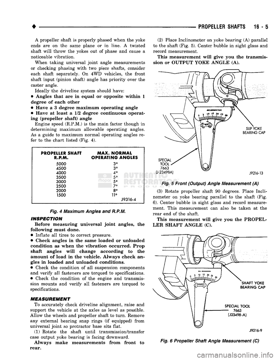
rear. (2) Place Inclinometer on yoke bearing (A) parallel
to the shaft (Fig. 5). Center bubble in sight glass and
record measurement.
This measurement will give you the transmis
sion or OUTPUT YOKE ANGLE (A).
Fig.
5 Front (Output)
Angle
Measurement (A)
(3) Rotate propeller shaft 90 degrees. Place Incli
nometer on yoke bearing parallel to the shaft (Fig.
6).
Center bubble in sight glass and record measure
ment. This measurement can also be taken at the
rear end of the shaft.
This measurement will give you the PROPEL
LER SHAFT ANGLE (C). J9216-9
Fig.
6 Propeller Shaft
Angle
Measurement (C)