Page 550 of 1502
WIRING
DIAGRAMS
8W - 75
Z8
18GY
PANEL
GROUND
Z09 18GY/BK
Bill
18LB -
_rrrRv_
(RIGHT 0F
~LL1U)
|
STEERING COLUMN)
(LEFT
REAR
FRAME
RAIL)
BLACK
B108 14WT/BR
-j=rf
B101 16LG/BK
-BLACK
18BK-
G11 18WT/BK
RESET
SWITCH
DUMP
ISO
SOL
BRAKE
WARNING
LAMP SWITCH
(LEFT
FRONT
FRAME
RAIL) DUAL SOLENOID
HYDRAULIC VALVE
GRAY
Gil
20WT
BK
BLUE
(LEFT
SIDE-UNDER INSTR/PANEL)
• • L50
18WT/TN
F32 20PK/DB
TO
BUZZER
(SEE
SH 77)
GROUND
SPLICE
(SEE
SH 48)
Bl13
18RD/VT
B114
18WT/VT
TO
HAZARD
L50
18WT/TN
?
FLASHER ^ SWITCH
(SEE
SH 56)
(TAPED
TO
HARNESS
NEAR
CONNECTOR) 8113
Bl14
18RD
18RD
VT
VT
F32 18PK/DB Zl
18BK 150
20WT/TN
Zl 20BK
V40
18WT/PK
TO
DATA LINK CONNECTOR
(SEE
SH 23)
RESISTOR
41
20PK
18WT V40
18WT
PK
i TO POWERTRAIN
CONTROL MODULE
II
CAVITY
29
(SEE
SH 37)
TWISTED
PAIR
BLACK
STOP
LAMP SWITCH
(LEFT FENDER
SIDE
SHIELD)
REAR WHEEL
ANT
I
-LOCK BRAKE SYSTEM
U938w-ii
(DIESEL ENGINE) R.W.A.L. SENSOR
(IN REAR DIFFERENTIAL)
AD
34
Page 565 of 1502
SW
- 90 WIRING DIAGRAMS
TO COMBINED
BUZZER
(SEE SH
77,78)
L30
18BR/YL
Zl
20BK
Ml 18PK
BLUE AD 49
MAP
LAMP AND CARGO LAMP
msu-n
Page 590 of 1502
•
WIRING DIAGRAMS 8W - 115 RIGHT DOOR SWITCH CONNECTOR
P33
160R/BK (LOCK)
P35
160R/VT
] —E
FORWARD
TERMINAL END
-BLUE
P36 16PK/VT
• F35 16RD
P34 1BPK/BK (UNLOCK)
t
UP
y-—•
• •—'
RIGHT FRONT DOOR SWITCH /
(VIEW FROM /
TERMINAL END) / BLACK—^
fTOPl
/
VLK
P36 P34
16PK 16PK VT BK F35 16RD-
P36 16PK/VT -J
P35
160R/VT-
P33
160R/BK- P34 16PK/BK
J938W-11 P34
16PK
BK
F35
16RD P35
160R VT
P33
160R/BK-P34 16PK/BK
POWER
DOOR LOCKS RIGHT FRONT
DOOR
MOTOR
^ LK X—\UNLK
to AD 74
Page 594 of 1502

WIRING
DIAGRAMS SW - 119
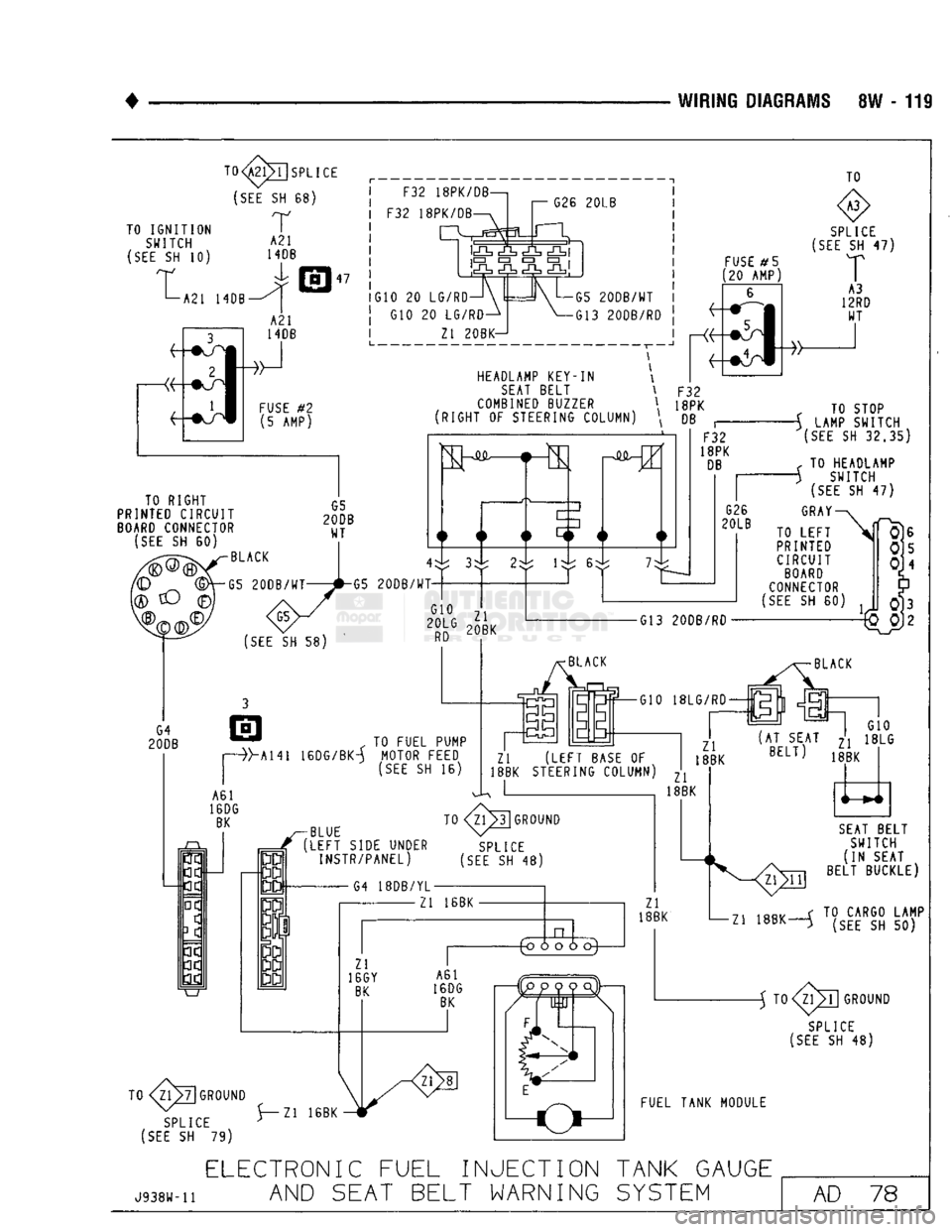
TO IGNITION SWITCH
(SEE
SH 10)
t 1—A21 HOB TO
1| SPLICE
(SEE
SH 68)
r
A21
HOB
47 F32 18PK/DB—,
F32 18PK/DB G26
20LB
lc£L
iCZD
• • • G10 20 LG/RD-
G10 20 LG/RD- Zl 20BK- ~1
G5
20DB/WT
G13 20DB/RD TO
FUSE
#5
[20 AMP)
SPLICE
(SEE
SH 47)
HEADLAMP KEY-IN
SEAT
BELT
COMBINED
BUZZER \ F32
\ 18PK
RIGHT OF STEERING COLUMN \ DB TO RIGHT
PRINTED CIRCUIT
BOARD
CONNECTOR
(SEE
SH 60)
(SEE
SH 58)
BLACK
G5
20DB/WT
G5
20DB/WT-
G10
20LG
Zl
20BK F32
18PK
DB
G26
20LB
TO STOP
-\ LAMP SWITCH
(SEE
SH
32,35)
< TO HEADLAMP
S SWITCH
(SEE
SH 47)
GRAY
TO LEFT
PRINTED CIRCUIT
BOARD
CONNECTOR
(SEE
SH 60)
•G13 20DB/RD
, TO FUEL PUMP
Hi41 16DG/BK-A MOTOR FEED
(SEE
SH 16) G10
Zl
(LEFT
BASE
OF
18BK STEERING COLUMN) ^ I , 18BK Zl
8BK (AT SEAT ^ 18LG
BELT>
18BK
^BLUE
r
(LEFT
SIDE UNDER INSTR/PANEL)
G4 18DB/YL- TO
3
GROUND
SPLICE
[SEE
SH 48)
Zl 16BK XL Zl
16GY
BK
TO 7|GROUND
SPLICE
(SEE
SH 79) \ z^20
5~Zl 16BK -HT A61
16DG
BK
4o
o o d
) c
F. it
JJ Zl
18BK Z1>11
SEAT
BELT
SWITCH
(IN SEAT
BELT BUCKLE) 71 1ftR. f TO CARGO LAMP
-Zl 18BK—^ (SEE SH 50) -5 TO
SPLICE
(SEE
SH 48)
FUEL TANK MODULE
J938W-11
ELECTRONIC
FUEL INJECTION TANK GAUGE
AND
SEAT BELT WARNING
SYSTEM
AD
78
Page 595 of 1502
8W - 120 WIRING
DIAGRAMS
TO TRANSMISSION
WIRING r
(SEE
SH 7 DIESEL)J
(SEE
SH 9 GAS)
TO
SPLICE
(SEE
SH 47) S
TO TURN
SIGNAL SWITCH
(SEE
SH 56)
T03
[SPLICE
(SEE
SH 48)
SPORT
UTILITY
LEFT
TAIL.
STOP
i TURN X2
SIGNAL 18GY
LAMP
LEFT
BACK-UP LAMP CAB I
CHASSIS
SWEPT
LINE
BOX
LEFT
TAIL.
STOP
I
TURN
SIGNAL LAMP -
LEFT
BACK-UP LAMP
LEFT
TAIL,
STOP
I
TURN Y9
SIGNAL ,ppv LAMP 18fY
LEFT
BACK-UP LAMP BLUE
(LEFT
SIDE UNDER I/P)
TO
81
SPLICE
(SEE
SH
77.78)
B2
18VT/BK
AD
79
REAR
LIGHTING
J938W-11
Page 598 of 1502
•
WIRING DIAGRAMS 8W - 123 F33
F33 El 18TN
18PK/RD
18PK/RD BLUE DOT TURN SIGNAL
FLASHER
(SEE
SH 56) L6 18RD/BK
L5 18RD
_ L5 18RD
V34
20WT/RD
A21 14DB
F20 18WT
F20 18WT
G5 20DB/WT
A3 12RD/WT
F35 16RD
F32 A31 18PK/DB
14BK/WT
GREEN
DOT
F21
E2
200R
F30 16RD/TN A4 12BK/RD
A4 12BK/RD
Ml 20PK
X12 20RD/WT
L5 18RD L5 14RD
V34 20WT/RD
12TN L19 18PK
HAZARD
L9 18BK/WT
X3
20BK/RD
F33 18PK/RD X2 18DG/RD_
A15 16PK
A22 12BK/0R V6 18DB
V6 18DB HAZARD
FLASHER
(SEE
SH 56)
HORN
RELAY
(SEE
SH 30)
FUSE
NO.
AMPS
COLOR
SHEET
1 2
GRAY
2,36,38
2
5
TAN
2, 10,
12.13,14,58,77,78
3 20 YELLOW
2.7,9,10,39
4 20 YELLOW
1.30.47
5
20 YELLOW
1
.77.78
6 20 YELLOW
1 ,73
7 15 LT BLUE
1,10.52
8 10
RED
2,10,61.63.65
9 20 YELLOW
2.10,31.33.56
10 20 YELLOW
2.10.54.55
11 30
GREEN
2.10.66,67.69
12 30 CIRCUIT BREAKER
SILVER
CAN
2,10,71
13 20 YELLOW
1 ,56
14 3 VIOLET
1.47,52.61.63,65
15 10
RED
1,49,51.52,61,63,65,75
J938W-H
FUSE BLOCK MODULE AND RELAY BANK
AD 82
Page 617 of 1502

9
- 12
ENGINES
•
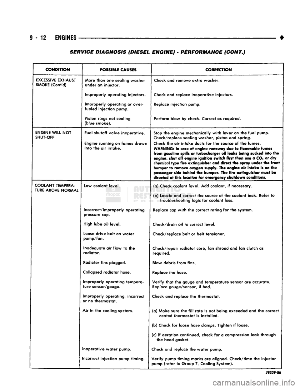
CONDITION
POSSIBLE
CAUSES
CORRECTION
EXCESSIVE
EXHAUST
SMOKE
(Cont'd)
More
than
one
sealing washer
under an injector.
Check
and remove
extra
washer.
Improperly operating injectors.
Check
and replace inoperative injectors.
Improperly operating or over-
fueled injection pump.
Replace
injection pump.
Piston
rings
not sealing
(blue smoke). Perform blow-by check. Correct as required.
ENGINE
WILL
NOT
SHUT-OFF
Fuel shutoff valve inoperative.
Engine
running on fumes drawn into the air intake.
Stop
the engine mechanically
with
lever on the
fuel
pump.
Check/replace
sealing washer, piston and
spring.
Check
the air intake ducts for the source of the fumes.
WARNING:
In
ease
of engine runaway due to flammable
fumes
from gasoline spills or turbocharger oil leaks
being
sucked
into the
engine,
shut off engine ignition switch first then use a CO* or dry
chemical type
fire
extinguisher
and direct the
spray
under
the
front
bumper to
remove
oxygen
supply. The engine air
intake
is on the
passenger
side
behind the bumper. The
fire
extinguisher
must
bo
directed at this location for emergency shutdown conditions.
COOLANT
TEMPERA
TURE
ABOVE
NORMAL
Low
coolant level.
(a) Check coolant level. Add coolant, if necessary.
(b) Locate and correct the source of the coolant leak. Refer to
troubleshooting
logic for coolant
loss.
Incorrect/improperly operating
pressure
cap.
Replace
cap
with
the correct rating for the
system.
High
lube oil level.
Check/drain
oil to correct level.
Loose
drive belt on water
pump/fan.
Check/replace
belt or belt tensioner.
Inadequate air flow to the radiator. Check/repair radiator core, fan shroud and fan clutch as
required.
Radiator
fins
plugged.
Blow
debris from fins.
Collapsed
radiator
hose.
Replace
the
hose.
Improperly operating tempera
ture
sensor/gauge.
Verify
that
the
gauge
and temperature
sensor
are accurate.
Replace
gauge/sensor,
if bad.
Improperly operating, incorrect
or
no thermostat.
Check
and replace the thermostat.
Air
in the cooling
system.
(a) Make sure the
fill
rate
is not being exceeded and the correct
vented thermostat is installed.
(b) Check for loose hose
clamps.
Tighten if
loose.
(c) If aeration continued, check for a
compression
leak through the head gasket.
Inoperative water pump.
Check
and replace the water pump.
incorrect injection pump timing. Verify pump timing marks are aligned. Check/time the injector
pump
(refer
to Group 7,
Cooling
System).
J9209-56
SERVICE DIAGNOSIS (DIESEL ENGINE) - PERFORMANCE (CONT.)
Page 631 of 1502

A
-
SEAT
WIDTH
-
INTAKE
1.016
-
1.524
mm
(0.040
-
0.060
in.)
EXHAUST
1.524
-
2.032
mm
(0.060
-
0.080
in.)
B
-
FACE
ANGLE
(INTAKE
& EXHAUST)
4374°
-
433A°
C
-
SEAT
ANGLE
(INTAKE
& EXHAUST)
4474°
-
44%°
D
-
CONTACT SURFACE
J9309-95
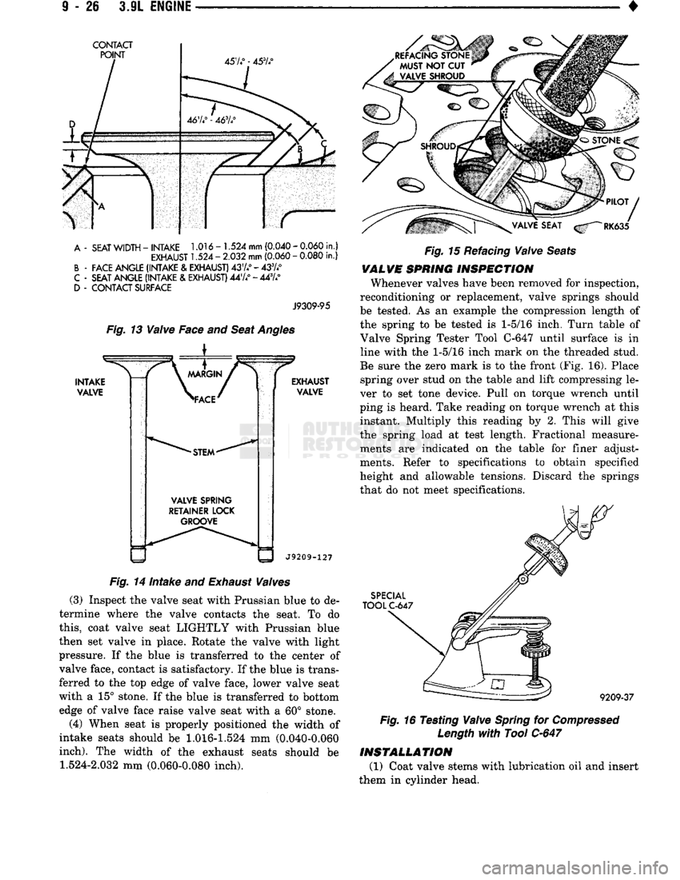
Fig.
13
Valve
Face and
Seat
Angles
i
INTAKE
VALVE
\
MARGIN
/ "
>FACE'
•STEM"
VALVE SPRING
RETAINER LOCK GROOVE EXHAUST
VALVE
J9209-127
Fig.
14 Intake and
Exhaust
Valves
(3) Inspect
the
valve seat with Prussian blue
to de
termine where
the
valve contacts
the
seat.
To do
this,
coat valve seat LIGHTLY with Prussian blue
then
set
valve
in
place. Rotate
the
valve with light
pressure.
If the
blue
is
transferred
to the
center
of
valve face, contact
is
satisfactory.
If
the blue
is
trans
ferred
to the top
edge
of
valve face, lower valve seat
with
a 15°
stone.
If
the blue
is
transferred
to
bottom edge
of
valve face raise valve seat with
a 60°
stone.
(4)
When seat
is
properly positioned
the
width
of
intake seats should
be 1.016-1.524 mm (0.040-0.060
inch).
The
width
of the
exhaust seats should
be 1.524-2.032 mm (0.060-0.080
inch).
Fig.
15 Refacing
Valve
Seats
VALVE
SPRING
INSPECTION
Whenever valves have been removed
for
inspection,
reconditioning
or
replacement, valve springs should
be tested.
As an
example
the
compression length
of
the spring
to be
tested
is 1-5/16
inch. Turn table
of
Valve Spring Tester Tool
C-647
until surface
is in
line with
the 1-5/16
inch mark
on the
threaded stud.
Be sure
the
zero mark
is to the
front (Fig.
16).
Place spring over stud
on the
table
and
lift compressing
le
ver
to set
tone device. Pull
on
torque wrench until
ping
is
heard. Take reading
on
torque wrench
at
this instant. Multiply this reading
by 2.
This will give
the spring load
at
test length. Fractional measure ments
are
indicated
on the
table
for
finer adjustments. Refer
to
specifications
to
obtain specified
height
and
allowable tensions. Discard
the
springs
that
do not
meet specifications.
SPECIAL
TOOL
C-647
9209-37
Fig.
16 Testing
Valve
Spring
for
Compressed
Length
with
Tool
C-647
INSTALLATION
(1)
Coat valve stems with lubrication
oil and
insert
them
in
cylinder head.