1993 DODGE TRUCK fuel pressure
[x] Cancel search: fuel pressurePage 934 of 1502
FUEL SYSTEM
14 - 115
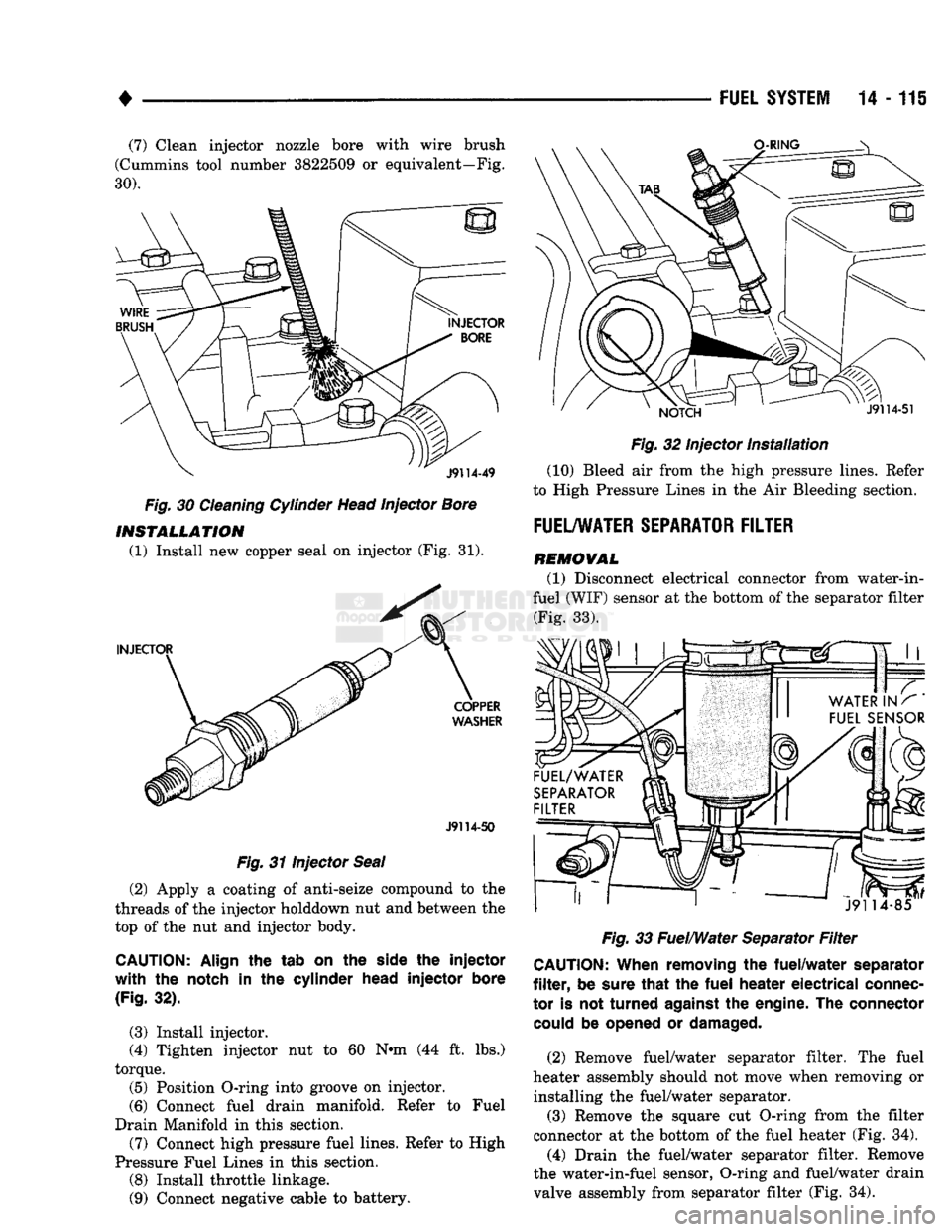
(7) Clean injector nozzle bore with wire brush
(Cummins tool number 3822509
or
equivalent—Fig.
30).
Fig.
30
Cleaning Cylinder Head Injector Bore INSTALLATION
(1) Install
new
copper seal
on
injector
(Fig. 31).
J9114-50
Fig.
31
Injector Seal
(2) Apply
a
coating
of
anti-seize compound
to the
threads
of the
injector holddown
nut and
between
the
top
of the nut and
injector body.
CAUTION:
Align
the tab on the
side
the injector
with the
notch
in the
cylinder
head
injector
bore
(Fig.
32).
(3) Install injector.
(4) Tighten injector
nut to 60 N«m (44 ft. lbs.)
torque. (5) Position O-ring into groove
on
injector.
(6) Connect fuel drain manifold. Refer
to
Fuel
Drain Manifold
in
this section.
(7) Connect high pressure fuel lines. Refer
to
High
Pressure Fuel Lines
in
this section.
(8) Install throttle linkage.
(9) Connect negative cable
to
battery.
Fig.
32
Injector
Installation
(10) Bleed
air
from
the
high pressure lines. Refer
to High Pressure Lines
in the Air
Bleeding section.
FUEL/WATER SEPARATOR FILTER
REMOVAL
(1) Disconnect electrical connector from water-in-
fuel (WIF) sensor
at the
bottom
of
the separator filter (Fig.
33).
Fig.
33
Fuel/Water Separator
Filter
CAUTION:
When
removing
the
fuel/water
separator
filter,
be
sure
that
the fuel
heater
electrical
connec
tor
is not
turned
against
the
engine.
The connector
could
be
opened
or
damaged.
(2) Remove fuel/water separator filter.
The
fuel
heater assembly should
not
move when removing
or
installing
the
fuel/water separator. (3) Remove
the
square
cut
O-ring from
the
filter
connector
at the
bottom
of the
fuel heater
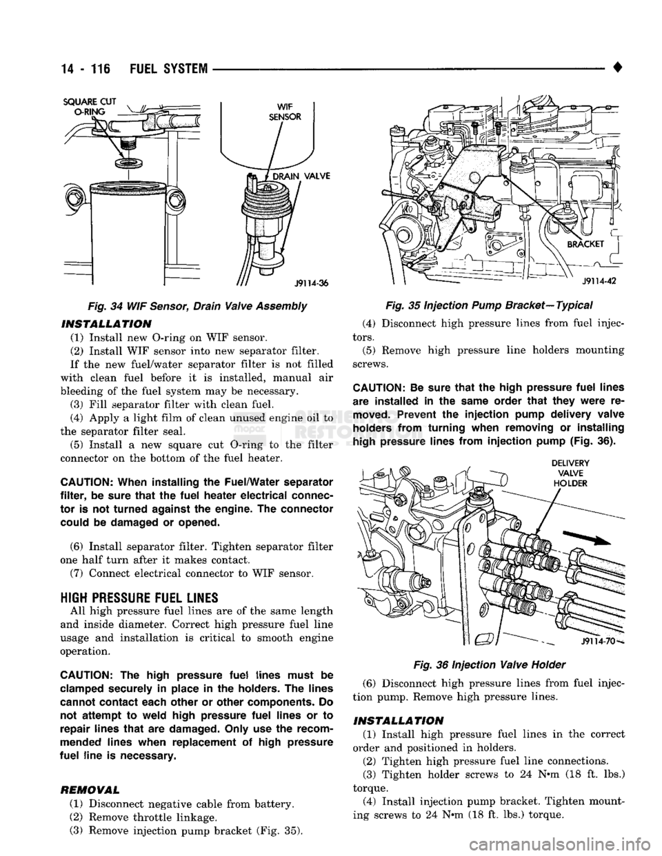
(Fig. 34).
(4) Drain
the
fuel/water separator filter. Remove
the water-in-fuel sensor, O-ring
and
fuel/water drain
valve assembly from separator filter
(Fig. 34).
Page 935 of 1502
14
• 116
FUEL
SYSTEM
Fig.
34 WIF
Sensor,
Drain
Valve
Assembly
INSTALLATION
(1) Install new O-ring on WIF sensor.
(2) Install WIF sensor into new separator filter.
If the new fuel/water separator filter is not filled
with clean fuel before it is installed, manual air
bleeding of the fuel system may be necessary. (3) Fill separator filter with clean fuel.
(4) Apply a light film of clean unused engine oil to
the separator filter seal.
(5) Install a new square cut O-ring to the filter
connector on the bottom of the fuel heater.
CAUTION:
When installing
the
Fuel/Water separator
filter,
be
sure
that
the
fuel
heater
electrical
connec
tor
is not
turned
against
the
engine.
The
connector could
be
damaged
or
opened.
(6) Install separator filter. Tighten separator filter
one half turn after it makes contact.
(7) Connect electrical connector to WIF sensor.
HIGH
PRESSURE
FUEL LINES
All high pressure fuel lines are of the same length
and inside diameter. Correct high pressure fuel line
usage and installation is critical to smooth engine
operation.
CAUTION:
The
high pressure
fuel
lines must
be
clamped securely
in
place
in the
holders.
The
lines
cannot contact each other
or
other components.
Do
not
attempt
to
weld high pressure
fuel
lines
or to
repair lines
that
are
damaged. Only
use the
recom
mended lines when replacement
of
high pressure
fuel
line
is
necessary.
REMOVAL
(1) Disconnect negative cable from battery.
(2) Remove throttle linkage.
(3) Remove injection pump bracket (Fig. 35).
Fig.
35 Injection
Pump
Bracket—
Typical
(4) Disconnect high pressure lines from fuel injec
tors.
(5) Remove high pressure line holders mounting
screws.
CAUTION:
Be
sure
that
the
high pressure
fuel
lines
are installed
in the
same order
that
they
were
re
moved.
Prevent
the
injection
pump delivery valve
holders from turning when removing
or
installing
high
pressure lines from
injection
pump (Fig.
36).
Fig.
36 Injection
Valve
Holder
(6) Disconnect high pressure lines from fuel injec
tion pump. Remove high pressure lines.
INSTALLATION
(1) Install high pressure fuel lines in the correct
order and positioned in holders.
(2) Tighten high pressure fuel line connections.
(3) Tighten holder screws to 24 N-m (18 ft. lbs.)
torque.
(4) Install injection pump bracket. Tighten mount
ing screws to 24 N*m (18 ft. lbs.) torque.
Page 936 of 1502
•
FUEL
SYSTEM
14-117
(5)
Bleed air from the fuel system. Refer to High
Pressure Fuel Lines in the Air Bleeding portion of
this section.
INJECTION
TIMING
If incorrect injection timing is suspected, injection
pump-to-engine timing or injection pump timing may
be the cause. Check injection pump timing before checking injection pump-to-engine timing.
INJECTION
PUMP
TIMING
CAUTION;
When
setting
injection
pump
timing,
re
fer to the engine
identification
plate
attached
to the
timing
case
flange for the
correct
specification
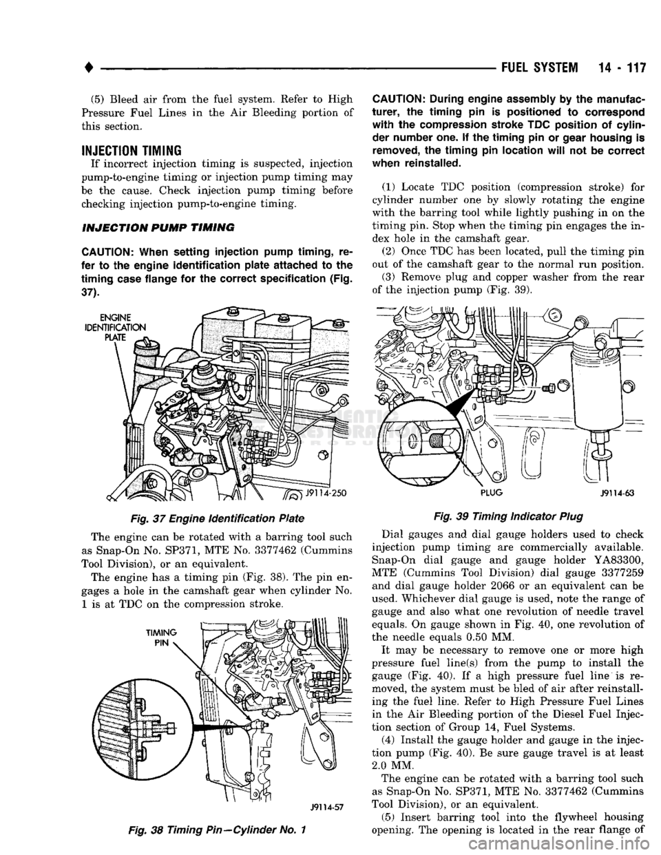
(Fig.
37). Fig. 37
Engine
identification Plate
The engine can be rotated with a barring tool such
as Snap-On No.
SP371,
MTE No. 3377462 (Cummins
Tool Division), or an equivalent.
The engine has a timing pin (Fig. 38). The pin en
gages a hole in the camshaft gear when cylinder No.
1
is at TDC on the compression stroke.
J9114-57
Fig. 38
Timing
Pin—Cylinder
No. 1
CAUTION:
During engine
assembly
by the manufac
turer,
the
timing
pin is positioned to correspond
with
the compression stroke TDC position of cylinder number one. If the
timing
pin or
gear
housing
is
removed,
the
timing
pin
location
will
not be
correct
when reinstalled.
(1)
Locate TDC position (compression stroke) for
cylinder number one by slowly rotating the engine
with the barring tool while lightly pushing in on the
timing pin. Stop when the timing pin engages the in dex hole in the camshaft gear. (2) Once TDC has been located, pull the timing pin
out of the camshaft gear to the normal run position.
(3) Remove plug and copper washer from the rear
of the injection pump (Fig. 39).
PLUG
J9114-63
Fig. 39
Timing Indicator
Plug
Dial gauges and dial gauge holders used to check
injection pump timing are commercially available. Snap-On dial gauge and gauge holder YA83300,
MTE (Cummins Tool Division) dial gauge 3377259 and dial gauge holder 2066 or an equivalent can be
used. Whichever dial gauge is used, note the range of
gauge and also what one revolution of needle travel
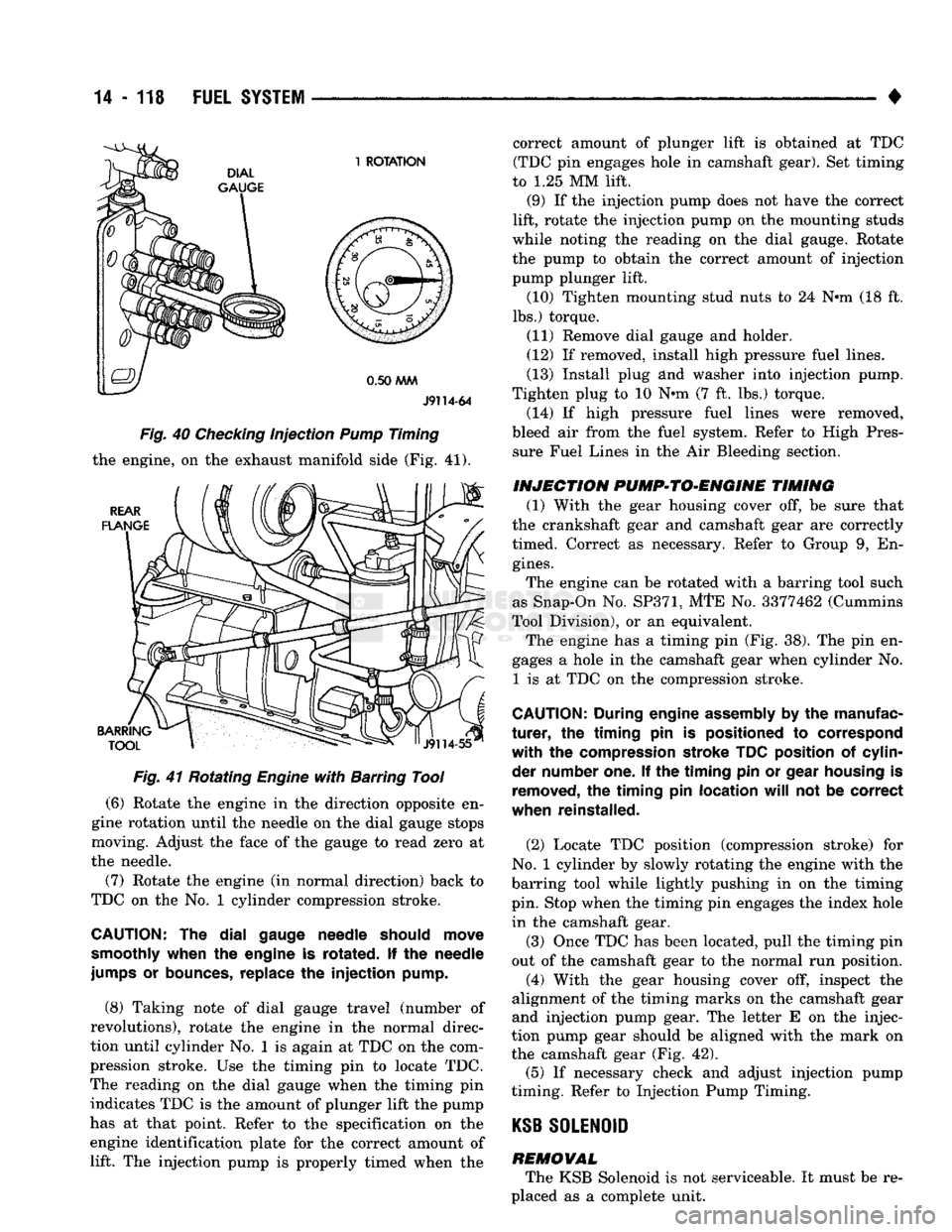
equals. On gauge shown in Fig. 40, one revolution of
the needle equals 0.50 MM.
It may be necessary to remove one or more high
pressure fuel line(s) from the pump to install the gauge (Fig. 40). If a high pressure fuel line is re
moved, the system must be bled of air after reinstall ing the fuel line. Refer to High Pressure Fuel Lines
in the Air Bleeding portion of the Diesel Fuel Injec
tion section of Group 14, Fuel Systems.
(4) Install the gauge holder and gauge in the injec
tion pump (Fig. 40). Be sure gauge travel is at least 2.0 MM. The engine can be rotated with a barring tool such
as Snap-On No. SP371, MTE No. 3377462 (Cummins
Tool Division), or an equivalent.
(5) Insert barring tool into the flywheel housing
opening. The opening is located in the rear flange of
Page 937 of 1502
14
- 118
FUEL
SYSTEM
•
J9114-64
Fig. 40 Checking injection Pump Timing
the engine, on the exhaust manifold side (Fig.
41).
Fig. 41 Rotating Engine with Barring Tool
(6)
Rotate the engine in the direction opposite en
gine rotation until the needle on the dial gauge stops
moving. Adjust the face of the gauge to read zero at
the needle.
(7) Rotate the engine (in normal direction) back to
TDC on the No. 1 cylinder compression stroke.
CAUTION:
The dial
gauge needle should move
smoothly when
the
engine
is
rotated.
If the
needle
jumps
or
bounces, replace
the injection
pump.
(8)
Taking note of dial gauge travel (number of
revolutions), rotate the engine in the normal direc
tion until cylinder No. 1 is again at TDC on the com
pression stroke. Use the timing pin to locate TDC.
The reading on the dial gauge when the timing pin indicates TDC is the amount of plunger lift the pump
has at that point. Refer to the specification on the
engine identification plate for the correct amount of lift. The injection pump is properly timed when the correct amount of plunger lift is obtained at TDC
(TDC pin engages hole in camshaft gear). Set timing
to
1.25
MM lift.
(9)
If the injection pump does not have the correct
lift, rotate the injection pump on the mounting studs
while noting the reading on the dial gauge. Rotate
the pump to obtain the correct amount of injection
pump plunger lift.
(10)
Tighten mounting stud nuts to
24
N*m
(18
ft.
lbs.) torque.
(11)
Remove dial gauge and holder.
(12)
If removed, install high pressure fuel lines.
(13)
Install plug tod washer into injection pump.
Tighten plug to
10
Nnn
(7
ft. lbs.) torque.
(14)
If high pressure fuel lines were removed,
bleed air from the fuel system. Refer to High Pres sure Fuel Lines in the Air Bleeding section.
INJECTION PVMP*>TO*ENGINE TIMING
(1)
With the gear housing cover off, be sure that
the crankshaft gear and camshaft gear are correctly
timed. Correct as necessary. Refer to Group
9,
En
gines.
The engine can be rotated with a barring tool such
as Snap-On No.
SP371,
MTE No.
3377462
(Cummins
Tool Division), or an equivalent. The engine has a timing pin (Fig.
38).
The pin en
gages a hole in the camshaft gear when cylinder No.
1
is at TDC on the compression stroke.
CAUTION;
During engine assembly
by the
manufac
turer, the timing pin is
positioned
to
correspond
with the
compression stroke TDC position
of
cylin
der number one.
If the timing pin or
gear housing
is
removed,
the timing pin
location
will
not be
correct
when reinstalled.
(2)
Locate TDC position (compression stroke) for
No.
1 cylinder by slowly rotating the engine with the
barring tool while lightly pushing in on the timing
pin. Stop when the timing pin engages the index hole in the camshaft gear.
(3)
Once TDC has been located, pull the timing pin
out of the camshaft gear to the normal run position.
(4)
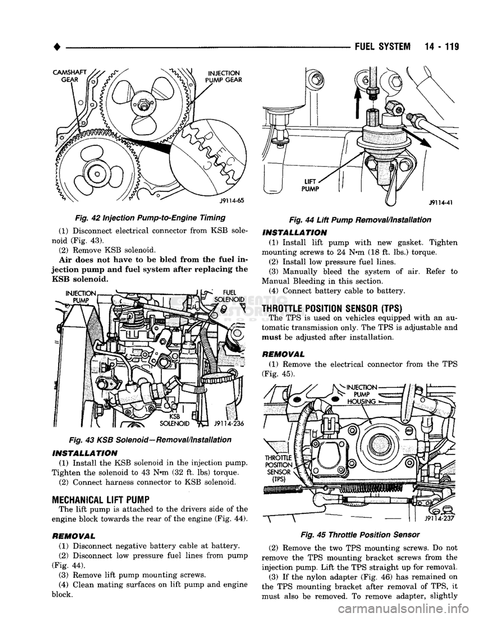
With the gear housing cover off, inspect the
alignment of the timing marks on the camshaft gear
and injection pump gear. The letter E on the injec
tion pump gear should be aligned with the mark on
the camshaft gear (Fig.
42).
(5)
If necessary check and adjust injection pump
timing. Refer to Injection Pump Timing.
KSB
SOLENOID
REMOVAL The KSB Solenoid is not serviceable. It must be re
placed as a complete unit.
Page 938 of 1502
•
Fig. 42 Injection
Pump-to-Engine
Timing
(1) Disconnect electrical connector from KSB sole
noid (Fig. 43).
(2) Remove KSB solenoid.
Air does not have to be Med from the fuel in
jection pump and fuel system after replacing the KSB solenoid.
Fig. 43 KSB Solenoid—Removal/installation INSTALLATION
(1) Install the KSB solenoid in the injection pump.
Tighten the solenoid to 43 N*m (32 ft. lbs) torque. (2) Connect harness connector to KSB solenoid.
MECHANICAL
LIFT
PUMP
The lift pump is attached to the drivers side of the
engine block towards the rear of the engine (Fig. 44).
REMOVAL (1) Disconnect negative battery cable at battery.
(2) Disconnect low pressure fuel lines from pump
(Fig. 44).
(3) Remove lift pump mounting screws.
(4) Clean mating surfaces on lift pump and engine
block.
FUEL
SYSTEM
14 - 119
Fig.
44 Lift
Pump
Removal/Installation INSTALLATION
(1) Install lift pump with new gasket. Tighten
mounting screws to 24 N#m (18 ft. lbs.) torque.
(2) Install low pressure fuel lines.
(3) Manually bleed the system of air. Refer to
Manual Bleeding in this section. (4) Connect battery cable to battery.
THROTTLE
POSITION
SENSOR
(TPS) The TPS is used on vehicles equipped with an au
tomatic transmission only. The TPS is adjustable and
must be adjusted after installation.
REMOVAL (1) Remove the electrical connector from the TPS
(Fig. 45).
Fig.
45
Throttle
Position
Sensor
(2) Remove the two TPS mounting screws. Do not
remove the TPS mounting bracket screws from the injection pump. Lift the TPS straight up for removal. (3) If the nylon adapter (Fig. 46) has remained on
the TPS mounting bracket after removal of TPS, it
must also be removed. To remove adapter, slightly
Page 942 of 1502
•
FUEL
SYSTEM
14 - 123
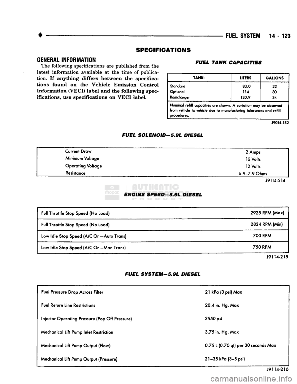
SPECIFICATIONS
GENERAL
INFORMATION
The following specifications
are
published from
the
latest information available
at the
time
of
publica
tion.
If
anything differs between
the
specifica
tions found
on the
Vehicle Emission Control Information (VECI) label
and the
following spec
ifications,
use
specifications
on
VECI label. FUEL TANK CAPACITIES
TANK:
LITERS GALLONS
Standard
83.0 22
Optional 114
30
Ramcharger
120.9
34
Nominal
refill
capacities
are
shown.
A
variation
may be
observed
from vehicle
to
vehicle
due to
manufacturing tolerances
and refill
procedures.
FUEL SOLENOID-5.9L DIESEL
J9014-182
Current Draw
2
Amps
Minimum Voltage 10 Volts
Operating Voltage 12 Volts
Resistance 6.9-7.9 Ohms
J9114-214
ENGINE SPEED—5.9L DIESEL
Full Throttle Stop Speed
(No
Load) 2925 RPM (Max)
Full Throttle Stop Speed
(No
Load)
2824
RPM (Min)
Low Idle Stop Speed (A/C On—Auto Trans) 700 RPM
Low Idle Stop Speed (A/C On—Man Trans) 750 RPM
J9114-215
FUEL SYSTEM—5*9L DIESEL
Fuel Pressure Drop Across Filter 21
kPa
(3 psi) Max
Fuel Return Line Restrictions 20.4 in. Hg. Max
Injector Operating Pressure (Pop
Off
Pressure) 3550
psi
Mechanical Lift Pump Inlet Restriction 3.75 in. Hg. Max
Mechanical Lift Pump Output (Flow) 0.75
L
(0.70 qt)
per 30
seconds Max
Mechanical Lift Pump Output (Pressure) 21-35 kPa (3-5 psi)
J9114-216
Page 944 of 1502
• —_ —_
FUEL
SYSTEM
14 - 125
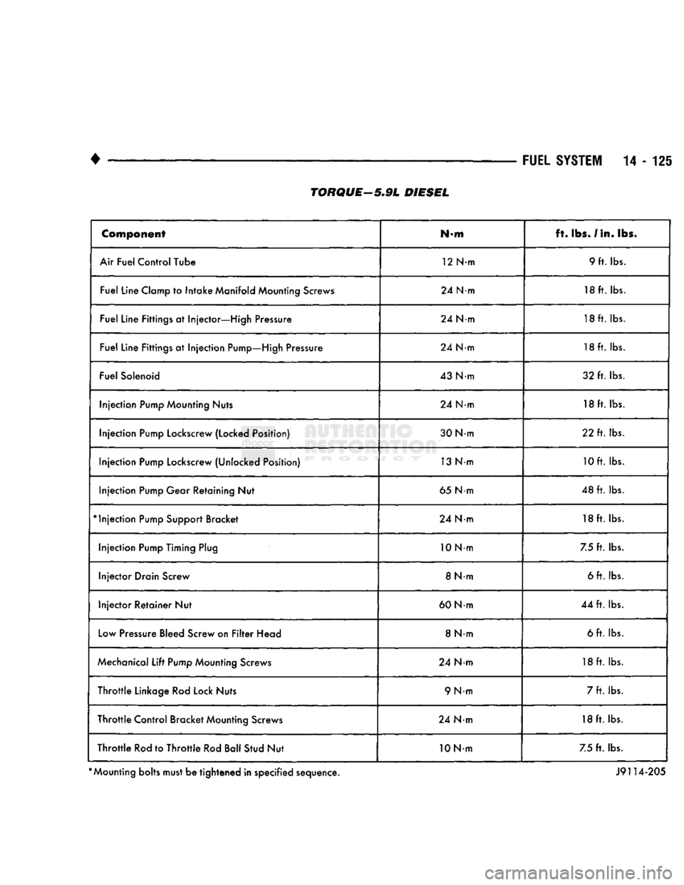
Component
N-m ft.
lbs.
/In. lbs.
Air Fuel Control Tube 12 N-m 9 ft. lbs.
Fuel Line Clamp to Intake Manifold Mounting Screws 24 N-m 18 ft. lbs.
Fuel Line Fittings at Injector—High Pressure 24 N-m 18ft. lbs.
Fuel Line Fittings at Injection Pump—High Pressure 24 N-m 18ft. lbs.
Fuel Solenoid 43 Nm 32 ft. lbs.
Injection Pump Mounting Nuts 24 N-m 18ft. lbs.
Injection Pump Lockscrew (Locked Position) 30 Nm 22 ft. lbs.
Injection Pump Lockscrew (Unlocked Position) 13 Nm 10ft. lbs.
Injection Pump Gear Retaining Nut 65 Nm 48 ft. lbs.
*
Injection Pump Support Bracket 24 Nm 18 ft. lbs.
Injection Pump Timing Plug 10Nm
7.5 ft. lbs.
Injector Drain Screw 8 N-m 6 ft. lbs.
Injector Retainer Nut 60 Nm 44 ft. lbs.
Low Pressure Bleed Screw on Filter Head 8 Nm 6 ft. lbs.
Mechanical Lift Pump Mounting Screws 24 Nm 18ft. lbs.
Throttle Linkage Rod Lock Nuts 9 N-m 7 ft. lbs.
Throttle Control Bracket Mounting Screws 24 Nm 18 ft. lbs.
Throttle Rod to Throttle Rod Ball Stud Nut 10 Nm 7.5 ft. lbs.
*
Mounting bolts must be tightened in specified sequence. J9114-205
TORQUE—5.9L
DIESEL
Page 1052 of 1502
•
• release fork ball stud
• propeller shaft slip yoke
APPLY
LIGHT
COAT
OF
HI-TEMP
GREASE
TO
THESE
SURFACES
BEFORE
INSTALLATION
J9106-15
Fig.
18 input Shaft Lubrication
Points
(Typical)
(3) Align transmission and clutch housing. Move
transmission forward and start input shaft into re lease bearing and clutch disc hub. Rotate output
shaft with socket or yoke to align input shaft and
clutch disc splines if necessary.
(4) Move transmission forward and seat transmis
sion against housing. (5) Install and tighten transmission mounting
bolts to 68 N-m (50 ft-lbs). (6) Install rear crossmember and crossmember
brackets. Start all crossmember bolts/nuts before
tightening to final torque of 68 N»m (50 ft-lbs). (7) Remove transmission jack.
(8) Install screws that attach fuel line clamps to
driver side frame rail. (9) Align clutch slave cylinder in housing and
tighten cylinder attaching nuts. (10) Install clutch slave cylinder shield.
(11) Secure backup light and vehicle speed sensor
wires in clips at top of transmission. Route wires across top of transmission to sensor and switch and
connect wires.
(12) Align and install propeller shaft. Support
shaft on box or stand. Install shaft front U-joint first.
Next, secure center bearing bracket to frame bracket.
Then install shaft rear U-joint in axle yoke. Final- tighten U-joint clamp bolts to 19 N@m (14 ft-lbs) and center bearing bracket bolts to 68 N»m (50 ft-lbs). (13) Lower vehicle.
(14) Lubricate shift lever ball and collar with Mo
par all purpose grease. (15) Align notches in shift lever ball and collar
and insert shift lever in shift tower. (16) Press shift lever and collar downward and in
stall shift lever snap ring. (17) Tighten shift lever alignment bolts com
pletely. (18) Install boot over shift lever and onto shift
tower and tighten boot clamp securely. (19) Install lower boot and plate assembly over
shift lever and onto floorpan. Position plate so large G360
MANUAL TRANSMISSION
21 - 51
SKID
PLATE
J9121-525
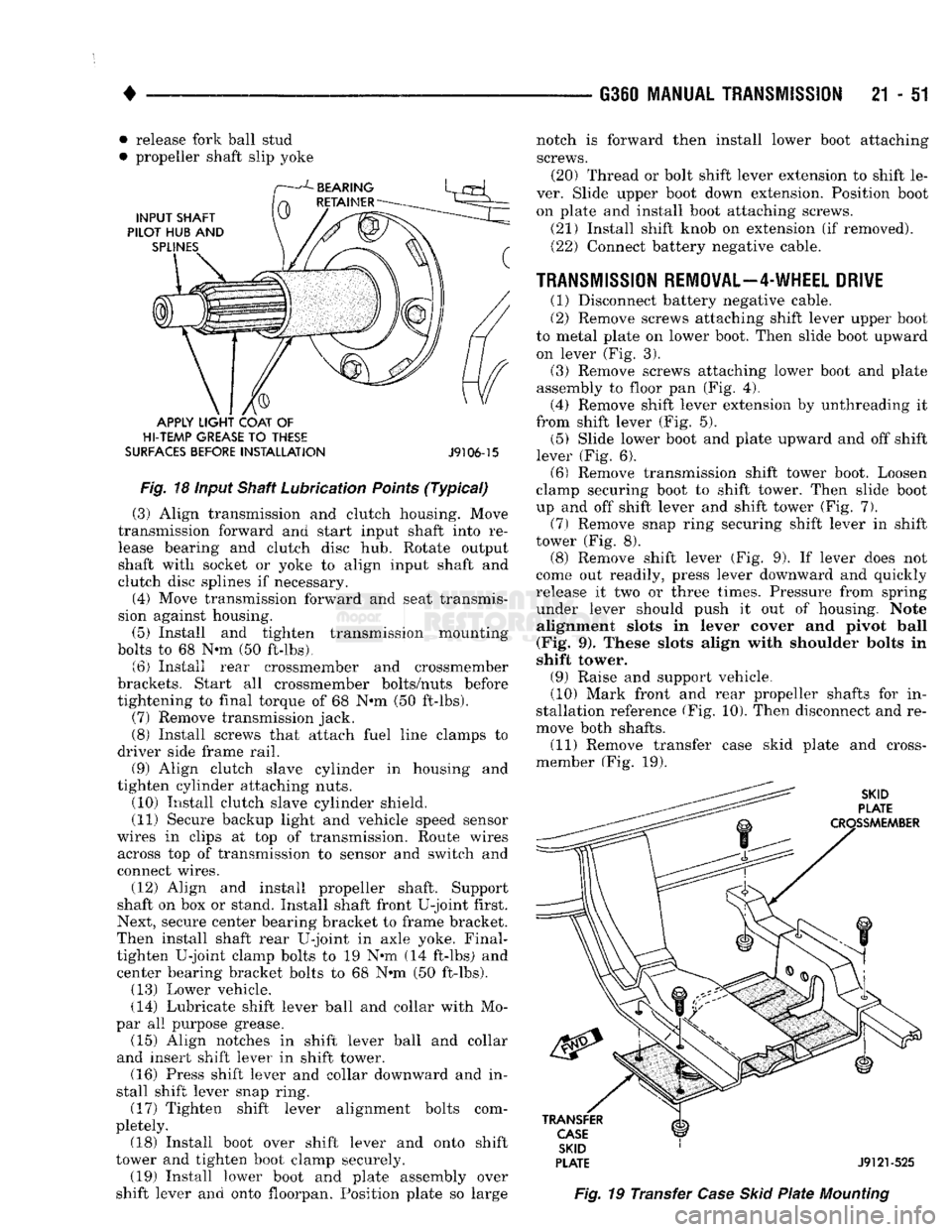
Fig.
19 Transfer
Case
Skid
Plate
Mounting
notch is forward then install lower boot attaching
screws. (20) Thread or bolt shift lever extension to shift le
ver. Slide upper boot down extension. Position boot on plate and install boot attaching screws.
(21) Install shift knob on extension (if removed). (22) Connect battery negative cable.
TRANSMISSION REMOVAL—4-WHEEL DRIVE
(1) Disconnect battery negative cable.
(2) Remove screws attaching shift lever upper boot
to metal plate on lower boot. Then slide boot upward on lever (Fig. 3).
(3) Remove screws attaching lower boot and plate
assembly to floor pan (Fig. 4). (4) Remove shift lever extension by unthreading it
from shift lever (Fig. 5). (5) Slide lower boot and plate upward and off shift
lever (Fig. 6). (6) Remove transmission shift tower boot. Loosen
clamp securing boot to shift tower. Then slide boot
up and off shift lever and shift tower (Fig. 7).
(7)
Remove snap ring securing shift lever in shift
tower (Fig. 8). (8) Remove shift lever (Fig. 9). If lever does not
come out readily, press lever downward and quickly
release it two or three times. Pressure from spring under lever should push it out of housing. Note alignment slots in lever cover and pivot ball
(Fig. 9). These slots align with shoulder bolts in
shift tower.
(9) Raise and support vehicle.
(10) Mark front and rear propeller shafts for in
stallation reference (Fig. 10). Then disconnect and re
move both shafts. (11) Remove transfer case skid plate and cross-
member (Fig. 19).