1993 DODGE TRUCK wiring diagram
[x] Cancel search: wiring diagramPage 602 of 1502
•
WIRING
DIAGRAMS
8W - 127
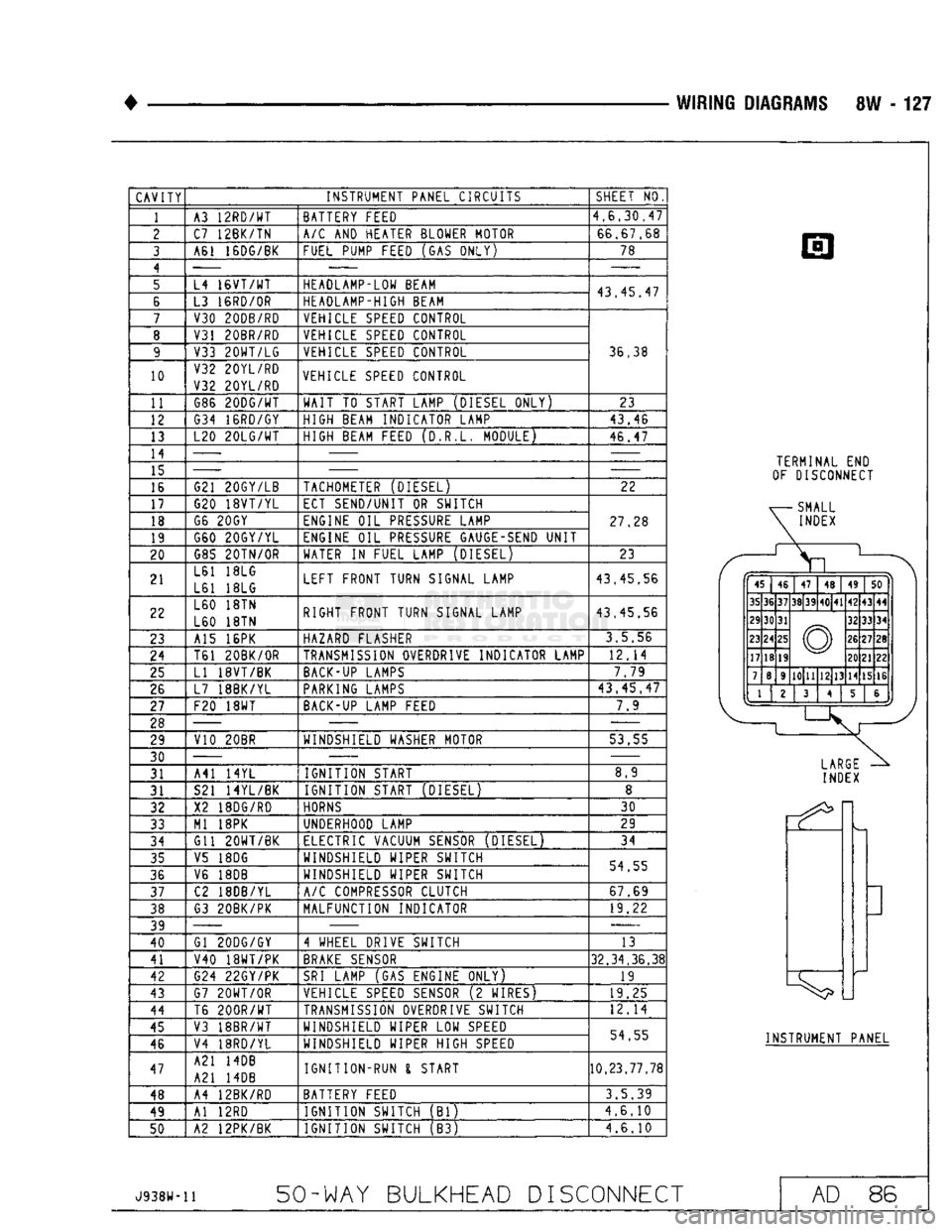
CAVITY
INSTRUMENT PANEL CIRCUITS
1
10
11
12
13
14
15
16
17
18
19
20
21
22
23
24
25
26
27
28 29
30 31
31
32
33
34
35
36
37
38
39
40
41
42
43
44
45
46
47
48
49
50
A3
12RD/WT
C7 12BK/TN
A61 16DG/BK
L4
16VT/WT
L3
16RD/0R
V30 20DB/RD
V31 20BR/RD
V33
20WT/LG
V32 20YL/RD
V32 20YL/RD G86
20DG/WT
G34 16RD/GY
L20
20LG/WT
G21 20GY/LB
G20
18VT/YL
G6
20GY
G60 20GY/YL G85
20TN/0R
L61
18LG
L61
18LG
L60
18TN
L60
18TN
A15
16PK
T61 20BK/OR
LI
18VT/BK
L7 18BK/YL
F20
18WT
V10 20BR
A41
14YL
S21 14YL/BK
X2
18DG/R0
Ml
18PK
Gil
20WT/BK
V5
18DG
V6
18DB
C2 18DB/YL
G3 20BK/PK
Gl 20DG/GY
V40
18WT/PK
G24 22GY/PK
G7
20WT/0R
T6
200R/WT
V3 18BR/WT
V4 18RD/YL
A21
14DB
A21
14DB
A4 12BK/RD
Al
12RD
A2 12PK/BK BATTERY FEED
A/C
AND
HEATER BLOWER MOTOR
FUEL PUMP FEED
(GAS
ONLY)
HEADLAMP-LOW BEAM
HEADLAMP-HIGH BEAM VEHICLE
SPEED
CONTROL
VEHICLE
SPEED
CONTROL VEHICLE
SPEED
CONTROL
VEHICLE
SPEED
CONTROL
WAIT
TO
START LAMP (DIESEL ONLY)
HIGH BEAM INDICATOR LAMP
HIGH BEAM FEED (D.R.L. MODULE)
TACHOMETER (DIESEL)
ECT SEND/UNIT
OR
SWITCH
ENGINE
OIL
PRESSURE
LAMP
ENGINE
OIL
PRESSURE
GAUGE-SEND
UNIT
WATER
IN
FUEL LAMP (DIESEL)
LEFT FRONT TURN SIGNAL LAMP
RIGHT FRONT TURN SIGNAL LAMP
HAZARD FLASHER
TRANSMISSION
OVERDRIVE INDICATOR LAMP
BACK-UP
LAMPS
PARKING
LAMPS
BACK-UP
LAMP FEED
WINDSHIELD WASHER MOTOR
IGNITION START
IGNITION START (DIESEL)
HORNS
UNDERHOOD LAMP
ELECTRIC VACUUM
SENSOR
(DIESEL) WINDSHIELD WIPER SWITCH
WINDSHIELD WIPER SWITCH
A/C
COMPRESSOR CLUTCH
MALFUNCTION INDICATOR
4 WHEEL DRIVE SWITCH
BRAKE
SENSOR
SRI
LAMP
(GAS
ENGINE ONLY)
VEHICLE
SPEED
SENSOR
(2
WIRES)
TRANSMISSION
OVERDRIVE SWITCH
WINDSHIELD WIPER
LOW
SPEED
WINDSHIELD WIPER HIGH
SPEED
IGNITION-RUN
I
START
BATTERY FEED IGNITION SWITCH
(Bl)
IGNITION SWITCH
(B3)
SHEET
NO
4,6.30,47
66,67,68 78
43,45,47
36,38
23
43,46
46,47
22
27,28
23
43.45,56
43,45.56
3,5,56
12,14 7.79
43,45,47
7.9
53.55 8,9
30
29
34
54,55 67,69 19,22
13
32,34,36,38
19
19,25
12,14
54.55
10,23.77,78
3.5.39
4,6.10
4.6.10
TERMINAL
END
OF DISCONNECT
ff
p
45 46
47
48 49
50
35 36 37
38 39
40 41
42
43 44
29 30 31
© 32
33 34
23 24
25
© 26
27 28
17 18
19 ©
20 21 22
7 8 9
10 11
12 13
14 15 16
1
^
1.
2
3
4 5 &
J *j
LARGE
INDEX
INSTRUMENT PANEL
J938W-11
50-WAY BULKHEAD
DISCONNECT
AD
86
Page 603 of 1502
8W - 128 WIRING
DIAGRAMS
• 10
11 12
13
14
15 16 17
18 19
20
21 22
23 24
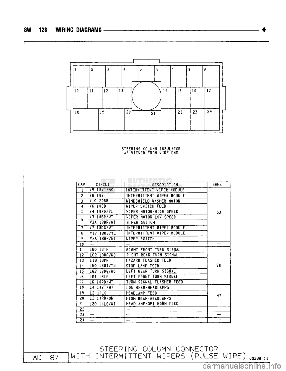
STEERING
COLUMN INSULATOR
AS
VIEWED FROM WIRE END
CAV
CIRCUIT
DESCRIPTION SHEET
1
V9
18WT/BK
INTERMITTENT WIPER MODULE
2 V8 18VT
INTERMITTENT WIPER MODULE
3 V10 20BR
WINDSHIELD WASHER MOTOR
4 V6 18DB
WIPER SWITCH FEED
5 V4 18RD/YL
WIPER MOTOR-HIGH SPEED
53
6 V3 18BR/WT
WIPER MOTOR-LOW SPEED
6
V3A 18BR/WT WIPER SWITCH
7 V7
18DG/WT
INTERMITTENT WIPER MODULE
8
V17 18DG/YL INTERMITTENT WIPER MODULE
9 V3A 18BR/WT
WIPER SWITCH
10 —
— —
11 L60 18TN
RIGHT FRONT TURN SIGNAL
12 L62 18BR/RD RIGHT REAR TURN SIGNAL
13 L19 18PK HAZARD FLASHER FEED
14 L50
18WT/TN
STOP LAMP FEED 56
15 L63 18DG/RD LEFT REAR TURN SIGNAL
16 L61 18LG LEFT FRONT TURN SIGNAL
17 L6
18RD/WT
TURN SIGNAL FLASHER FEED
18 L4
14VT/WT
LOW BEAM-HEADLAMPS
19 L2 14LG HEADLAMP FEED
47
20 L3
14RD/0R
HIGH BEAM-HEADLAMPS 47
21 L20
14LG/WT
HEADLAMP-OPT HORN FEED
22 —
— —
23 —
—
24 — —-
—
AD
87
STEERING
COLUMN CONNECTOR
WITH
INTERMITTENT WIPERS (PULSE WIPE)
J938W.n
Page 604 of 1502
•
WIRING DIAGRAMS 8W - 129 1
1
2 3
4 5
6
7
8 9
1
2 3
(
\ ) 7
8 9
10 11 12 13
(
\ ) 14
15 16 17
18 19
20 ^-— -
21 22
23 24
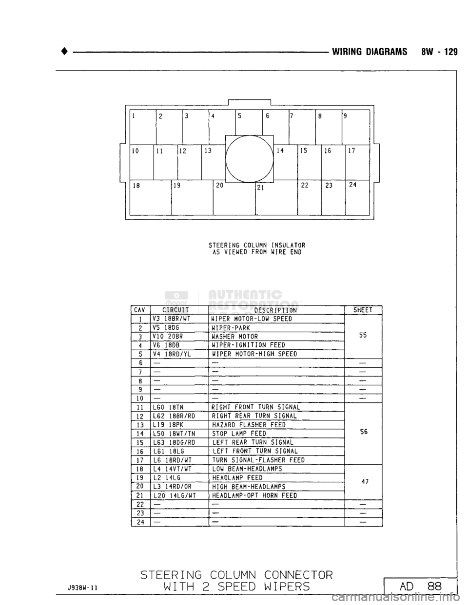
STEERING COLUMN INSULATOR
AS
VIEWED FROM WIRE END
CAV CIRCUIT
DESCRIPTION SHEET
1
V3
18BR/WT
WIPER MOTOR-LOW SPEED
55
2
V5 18DG
WIPER-PARK
55
3 V10
20BR
WASHER MOTOR 55
4 V6 18DB
WIPER-IGNITION FEED 55
5 V4
18RD/YL
WIPER MOTOR-HIGH SPEED 55
6 —
— —
7 —
— —
8 —
— —
9 —
— —
10 —
— —
11 L60 18TN
RIGHT FRONT TURN SIGNAL
56
12
L62 18BR/RD
RIGHT REAR TURN SIGNAL
56
13
L19 18PK
HAZARD FLASHER FEED
56
14 L50
18WT/TN
STOP LAMP FEED 56
15 L63 18DG/RD
LEFT REAR TURN SIGNAL 56
16 L61 18LG
LEFT FRONT TURN SIGNAL 56
17 L6
18RD/WT
TURN SIGNAL-FLASHER FEED 56
18 L4
14VT/WT
LOW BEAM-HEADLAMPS
47
19
L2 14LG HEADLAMP FEED
47
20 L3 14RD/OR
HIGH BEAM-HEADLAMPS 47
21 L20
14LG/WT
HEADLAMP-OPT HORN FEED 47
22 —
— —
23 —
— —
24 —
—
—
J938H-11
STEERING
COLUMN CONNECTOR
WITH 2
SPEED
WIPERS
AD 88
Page 605 of 1502
8W - 130
WIRING
DIAGRAMS
•
1 2 3
A 4
5 6
7
8
/
9
10
11
/
12 13
14
15 16
/
17
18
19
20
21
u
22
23
24
25 26
u
27
28 29
30
31
u
32 33
34
u
35 36
37
38 39
u
40
41 42
u
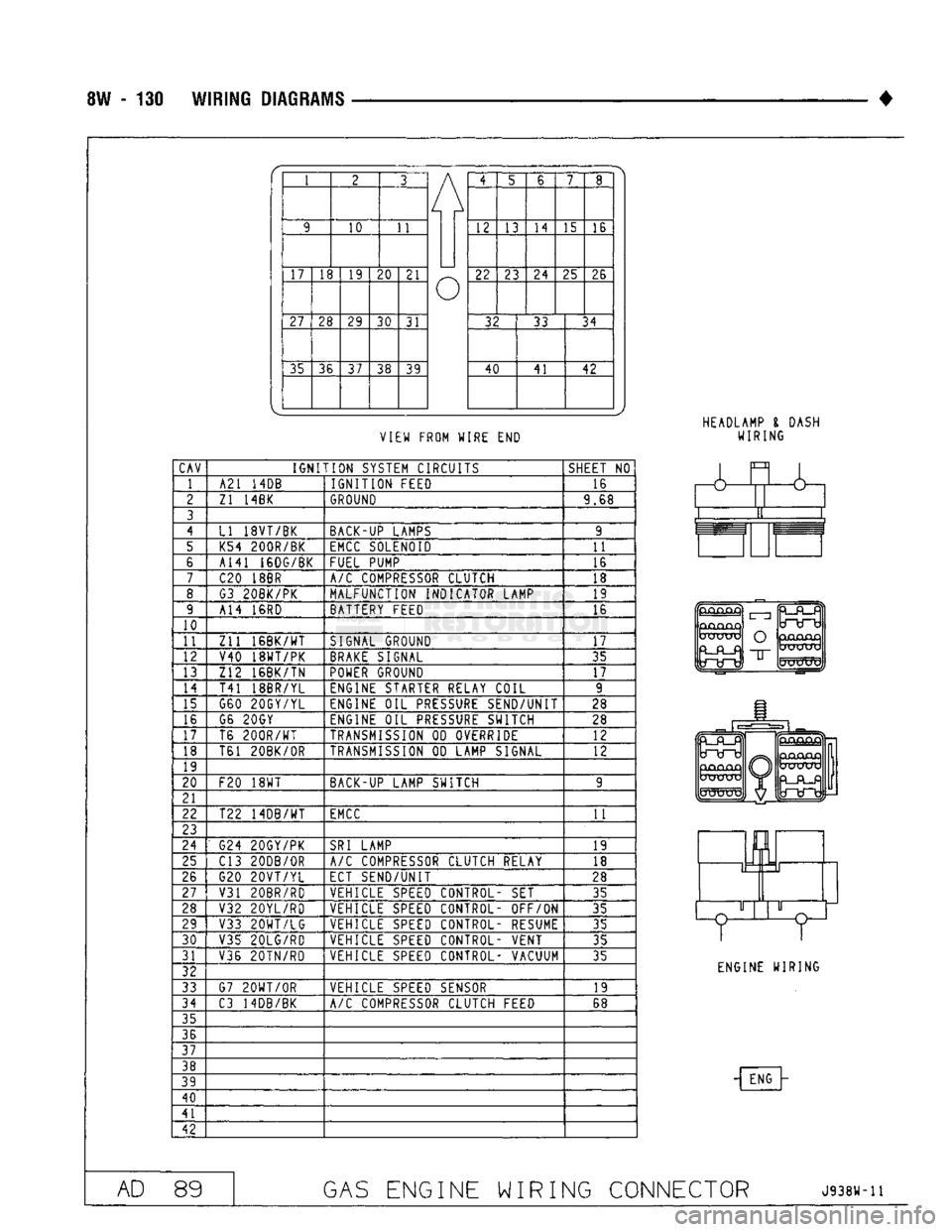
VIEW FROM WIRE
END
HEADLAMP
I
DASH
WIRING
CAV
IGNITION
SYSTEM CIRCUITS
SHEET
NO
1 A21
14DB
IGNITION
FEED 16
2
Zl 14BK
GROUND
9.68
3
4
LI 18VT/BK BACK-UP LAMPS 9
5 K54 200R/BK
EMCC
SOLENOID
11
6 A141 16DG/BK
FUEL PUMP 16
7
C20
18BR
A/C
COMPRESSOR CLUTCH 18
8 G3 20BK/PK MALFUNCTION INDICATOR LAMP 19
9 A14
16RD
BATTERY FEED 16
10
11
Zll
16BK/WT
SIGNAL GROUND
17
12 V40 18WT/PK
BRAKE
SIGNAL 35
13 Z12 16BK/TN
POWER
GROUND
17
14
T41 18BR/YL ENGINE STARTER RELAY COIL 9
15 G60 20GY/YL ENGINE
OIL
PRESSURE
SEND/UNIT 28
16 G6 20GY
ENGINE
OIL
PRESSURE
SWITCH 28
17 T6
200R/WT
TRANSMISSION
OD
OVERRIDE 12
18 T61 20BK/0R
TRANSMISSION
OD
LAMP SIGNAL
12
19
20
F20
18WT
BACK-UP LAMP SWITCH 9
21
22 T22 14DB/WT
EMCC
11
23
24
G24 20GY/PK
SRI
LAMP
19
25 C13 20DB/0R
A/C
COMPRESSOR CLUTCH RELAY
18
26 G20
20VT/YL
ECT SEND/UNIT
28
27
V31 20BR/RD VEHICLE
SPEED
CONTROL-
SET
35
28 V32 20YL/RD VEHICLE
SPEED
CONTROL- OFF/ON
35
29 V33
20WT/LG
VEHICLE
SPEED
CONTROL- RESUME 35
30
V35 20LG/RD VEHICLE
SPEED
CONTROL- VENT
35
31 V36 20TN/RD VEHICLE
SPEED
CONTROL- VACUUM
35
32
33 G7
20WT/0R
VEHICLE
SPEED
SENSOR 19
34
C3 14DB/BK
A/C
COMPRESSOR CLUTCH FEED 68
35
36
37
38
39
40
41
42
&
GjCUQjQ
UXJUXj
O
"IT
mJKXTV
ENGINE WIRING
- ENG
AD
89
GAS
ENGINE WIRING CONNECTOR
J938W-11
Page 790 of 1502
•
FRAME
AND
BUMPERS
13 - 3
SNOW
PLOW
NDEX
page
Power
Angling Cylinder Service
16
Power
Unit
. . 13
Service
Information
3
Snow
Plow Control Module
17
Snow
Plow Frame
16
SERVICE
INFORMATION
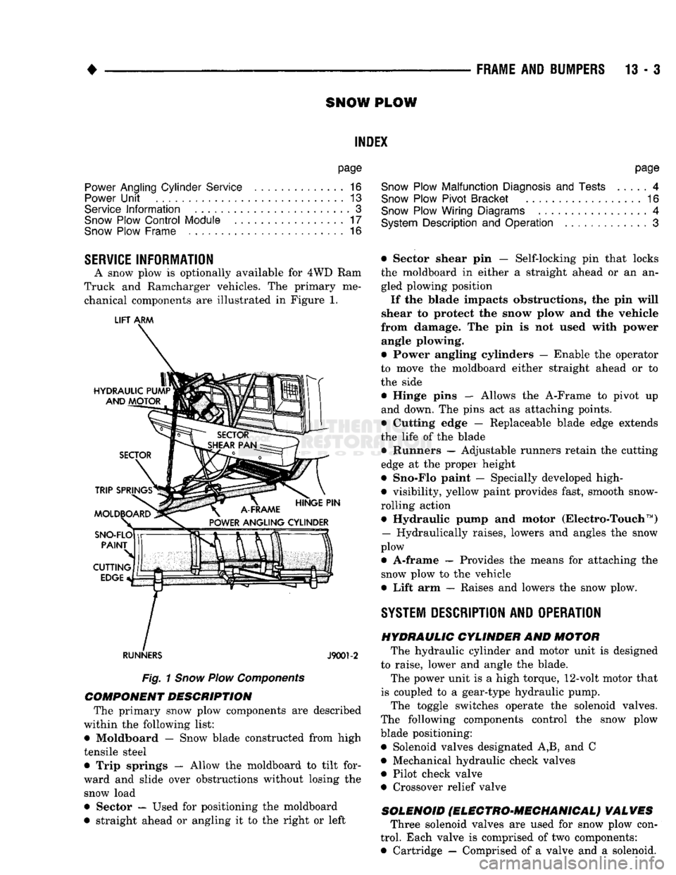
A snow plow is optionally available for 4WD Ram
Truck and Ramcharger vehicles. The primary me chanical components are illustrated in Figure 1.
LIFT
ARM
RUNNERS
J9001-2
Fig.
1
Snow
Plow
Components
COMPONENT DESCRIPTION
The primary snow plow components are described
within the following list:
• Moldboard — Snow blade constructed from high
tensile steel
• Trip springs — Allow the moldboard to tilt for
ward and slide over obstructions without losing the snow load
• Sector — Used for positioning the moldboard
• straight ahead or angling it to the right or left
page
Snow
Plow Malfunction
Diagnosis
and
Tests
4
Snow
Plow Pivot Bracket
16
Snow
Plow Wiring Diagrams
4
System
Description
and
Operation
3
• Sector shear pin — Self-locking pin that locks the moldboard in either a straight ahead or an an
gled plowing position
If the blade impacts obstructions, the pin will
shear to protect the snow plow and the vehicle
from damage. The pin is not used with power angle plowing.
• Power angling cylinders — Enable the operator
to move the moldboard either straight ahead or to
the side
• Hinge pins — Allows the A-Frame to pivot up
and down. The pins act as attaching points.
• Cutting edge — Replaceable blade edge extends
the life of the blade • Runners — Adjustable runners retain the cutting
edge at the proper height
• Sno-Flo paint — Specially developed high-
• visibility, yellow paint provides fast, smooth snow-
rolling action • Hydraulic pump and motor (Electro-Touch ™)
— Hydraulically raises, lowers and angles the snow
plow
• A-frame — Provides the means for attaching the snow plow to the vehicle
• Lift arm — Raises and lowers the snow plow.
SYSTEM
DESCRIPTION
AND OPERATION HYDRAULIC CYLINDER
AND
MOTOR
The hydraulic cylinder and motor unit is designed
to raise, lower and angle the blade. The power unit is a high torque, 12-volt motor that
is coupled to a gear-type hydraulic pump. The toggle switches operate the solenoid valves.
The following components control the snow plow blade positioning: • Solenoid valves designated A,B, and C
• Mechanical hydraulic check valves
• Pilot check valve
• Crossover relief valve
SOLENOID
fELEGTRO'MEGHANIGALj VALVES
Three solenoid valves are used for snow plow con
trol. Each valve is comprised of two components:
• Cartridge — Comprised of a valve and a solenoid.
Page 791 of 1502
13 - 4
FRAME
AND
BUMPERS
• • Coil — The electrical component that retracts the
cartridge solenoid.
With power applied, the solenoid retracts and pulls
the poppet valve into the OPEN position.
When power is turned off, the spring forces the so
lenoid back to its normal, CLOSED position.
SOLENOID
VALVE
A The solenoid valve A cartridge contains a poppet
valve. This valve is normally de-energized in the CLOSED position. When closed, the valve retains
pressure in the lift cylinder. When it is energized (valve opened), it allows the fluid to flow from the
lift cylinder back to the reservoir. This enables the
plow blade to lower via gravity.
Solenoid valve A is designed to remain energized
(valve open) during plowing to provide a floating
blade position. This ensures that the plow blade is guided up-down by the surface deviations.
SOLENOID
VALVE
B The solenoid valve B cartridge contains a spool
valve. This valve is normally in the de-energized CLOSED position. This allows the fluid to flow to the
C solenoid. In the energized OPEN position, the fluid
is diverted to the lift cylinder. This causes the plow
blade to be raised.
SOLENOID
VALVE
C The solenoid valve C cartridge contains a spool
valve that is normally in the de-energized CLOSED
position. This allows the fluid to flow to the right- side power angling cylinder. This angles the blade to
the left. At the same time, it allows the fluid from
the retracting left-side power angling cylinder to re
turn to the pump reservoir. Energizing the solenoid valve will route fluid to
the left side angling cylinder. This angles the plow
blade to the right. Also, the fluid is forced from the
retracting right side cylinder. It flows through the C cartridge valve and returns to the pump reservoir.
MECHANICAL HYDRAULIC VALVES The mechanical hydraulic valves all have the same
function: they control the direction of the hydraulic
fluid flow.
CHECK
VALVES
Check valves allow fluid to flow freely in one direc
tion while preventing fluid from flowing in the oppo site direction.
A pump check valve is used to prevent fluid from
leaking back through the pump to the reservoir.
Two additional check valves are necessary because
solenoid valves B and C have some leakage.
One check valve is located between solenoid valve
B and the lift cylinder. It prevents fluid in the lift cylinder from leaking back through solenoid valve B.
If fluid leaks back, it could angle the blade to the
left. This would force fluid through solenoid valve C into the right side cylinder.
The other check valve is located between valve B
and valve C. It prevents fluid from being forced
through solenoid valve B.
PILOT CHECK VALVE
A pilot check valve has a piston in addition to a
ball seat and spring. A pilot check valve is located
between solenoid valve C and the reservoir. It has two functions:
• Prevents the hydraulic fluid in either angling cylinder from leaking back to the reservoir.
• Allows the hydraulic fluid from a retracting an
gling cylinder to return to the reservoir. The valve action is done by fluid moving the pis
ton, which forces the check ball off its seat.
CROSSOVER
RELIEF VALVE
This valve protects against damage by a sudden
impact against the end of the blade. This will cause
high hydraulic pressure to accumulate in one of the angling cylinders. The hydraulic pressure increases enough to open
the crossover relief valve. The valve allows the
highly pressurized hydraulic fluid to flow to the other cylinder. This cushions the impact and changes
the position of the blade.
SYSTEM OPERATION Refer to Figures 2 through 5 for voltage application
and hydraulic fluid flow for each snow plow function.
Each figure shows the components that are actuated
for each function.
SNOW
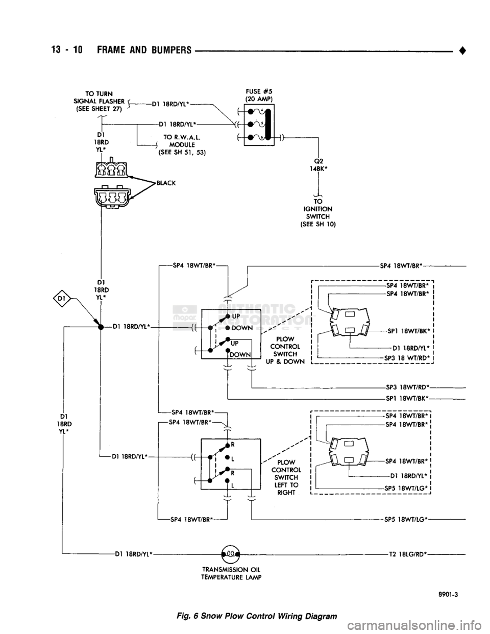
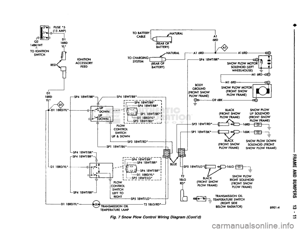
PLOW WIRING DIAGRAMS
Refer to Figures 6, 7 and 8 for wiring diagrams.
Refer to Specifications chart at the end of this
group.
SNOW PLOW MALFUNCTION DIAGNOSIS
AND
TESTS
Refer to the charts and illustrations for proper di
agnosis.
SOLENOID VALVE COIL FUNCTIONAL TEST Test the coils for proper operation, according to the
following procedure. (1) Hold a screwdriver blade about 1/8 inch above
the nut on the coil to be tested. (2) Have a helper operate the control switch that
energizes the applicable coil.
CAUTION:
Do not connect an ohmmeter to a coil
when it is
applied.
This
can
cause
internal
damage
to the ohmmeter.
(3) If the coil is working, the electromagnetic ac
tion will pull the screwdriver down to the retaining nut. If this does not occur, use an ohmmeter to check
the coil for continuity.
Page 797 of 1502
13
- 10
FRAME
AND
BUMPERS
TO TURN
SIGNAL
FLASHER
<
(SEE
SHEET
27) y -Dl 18RD/YL*
FUSE
#5
(20 AMP) Dl
18RD
YL*
-Dl 18RD/YL*
-Dl 18RD/YL*- Dl 18RD/YL*
TO R.W.A.L.
j MODULE
(SEE
SH
51, 53)
BLACK
TO
IGNITION
SWITCH
(SEE
SH
10)
-SP4
18WT/BR*
PLOW
CONTROL
SWITCH
UP
& DOWN L.
-SP4
18WT/BR*-
-SP4
18WT/BR*-
PLOW
CONTROL
SWITCH
LEFT
TO
RIGHT
-SP4
18WT/BR* -Dl 18RD/YL*-
TRANSMISSION
OIL
TEMPERATURE
LAMP
-SP4
18WT/BR*-
-SP4
18WT/BR*
-SP4
18WT/BR*
-SP1
18WT/BK* I Dl 18RD/YL*
-SP3
18 WT/RD*
-SP3
18WT/RD*-
-SP1
18WT/BK*-
SP4
18WT/BR* I
SP4
18WT/BR* !
-SP4
18WT/BR* j
—Dl 18RD/YL*
-SP5
18WT/LG* I
-SP5
18WT/LG*-
-T2 18LG/RD*-
8901-3
Fig. 6 Snow Plow
Control
Wiring
Diagram
Page 798 of 1502
SNOW PLOW DOWN
SOLENOID
(FRONT
SNOW
PLOW
FRAME)
SNOW PLOW
RIGHT SOLENOID
(FRONT
SNOW PLOW FRAME)
TRANSMISSION
OIL
TEMPERATURE LAMP TRANSMISSION
OIL
TEMPERATURE SWITCH
(RIGHT
SIDE
BELOW RADIATOR)
8901-4
Fig.
7
Snow
Plow Control Wiring Diagram (Cont'd)