1993 CHEVROLET PLYMOUTH ACCLAIM battery replacement
[x] Cancel search: battery replacementPage 719 of 2438
ity 9 and pin 7 of the control module 25-way connec-
tor. The vehicle speed sensor signal can be tested
with a volt/ohmmeter at pin 7 of the control module
25-way connector. Turn on the vehicle ignition and
check fo r a 5 volt signal as the vehicle is moved
about 3 to 5 feet. If not repair open wiring, terminal
push out, bad crimp, drive in vehicle speed sensor,
etc., as necessary to correct condition. Ensure that
the 25-way connector is plugged into the control
module securely. Road test vehicle after repairs have
been made to ensure that no recalls can occur while
moving.
CONDITION: INSTRUMENT CLUSTER SPEEDOMETER STAYS AT 0 MPH/ (0 KM/H)WHILE VEHICLE IS MOVING, BODYCOMPUTER DOES NOT LOCK DOORS AT 15MPH (24 KM/H), AND THE SPEED CONTROLWILL NOT ACCEPT A SPEED SET.
PROCEDURE
(1) Remove driver's seat anchor bolts and nuts. Ad-
just the driver's seat to a safe driving position. Dis-
connect the 25-way connector from the memory seat
control module. Replace the driver's seat anchor bolts
and nuts. Road test the vehicle to complete this diag-
nosis. If the doors lock, the cruise control accepts a
set, and the speedometer now works, replace the
Memory Seat control module. (2) After replacing the Memory Seat control mod-
ule, perform the memory seat diagnostic self tests.
This teaches the new module it's soft limits and now
re-road test the vehicle before returning it to the cus-
tomer.
CONDITION: NO SEAT MOVEMENT IN THE RECALL MODE, SEAT WILL MOVE BYMANUAL SWITCH ACTUATION IN ALLDIRECTIONS WITHOUT STALL DETECTION.
PROCEDURE
(1) Check for 5 volts at pin 10 of the control mod-
ule 25-way connector. This is the 5 volt feed from the
control module to the seat track position sensing po-
tentiometer. (2) Check for ground at pin 8 of the control module
25-way connector. To test for ground, one lead of the
voltmeter must be connected to either the 5 volt sup-
ply for the control module or the battery positive. If
the sense voltage and ground are NOT present at the
above pins of the 21-way control module connector.
When the seat switch is pressed, replace the control
module. An inadvertent application of battery volt-
age to the circuit could damaged the control module.
If the voltage and ground circuits are present then
continue this procedure. (3) Check for 5 volts at pin 5 of the natural 5-way
connector plugged into the power seat adjuster mo-
tors end-bell. (4) Check for ground at pin 4 of the natural 5-way
connector plugged into the power seat adjuster mo-
tors end-bell. If the power seat adjuster still has no
movement in the recall mode, then continue this pro-
cedure. (5) Disconnect the natural 5-way connector from
the power seat adjuster motors end-bell. (6) Check with an ohmmeter for a resistance read-
ing that may be from 2600 to 4000 ohms between
pins 4 and 5 of the motors end-bell connector. If
there is an open circuit reading or the reading ob-
tained falls outside this range, then replace the seat
motor package assembly. After replacement of the
seat motor package, reconnect all wiring connectors
and reinstall seat assembly in vehicle. Operate the
switches manually to cause maximum seat move-
ment in all directions. Perform the memory seat di-
agnostic self check so the control module will learn
the new soft limits of the assembly.
CONDITION: NO SEAT TRACK FORWARD OR REARWARD MOVEMENT IN THE RECALLMODE, SEAT TRACK WILL MOVE FORWARDOR REARWARD BY MANUAL SWITCHACTUATION WITHOUT STALL DETECTION.
PROCEDURE
(1) Check for a voltage at pin 12 of the control
module 21-way connector. Less than 5 volts for the
seat track fully forward and more than 0 volts when
fully rearward. This voltage should vary correspond-
ing to the position. (2) Check for a voltage at pin 1 of the natural
5-way connector, Same as in step (1) above. The
ground lead connected to pin 4 of the 5-way connec-
tor. If the voltage reading is at 0 volts, disconnect
the 5-way natural connector and check for a short to
ground in the harness. If no short is found, reconnect
the connector and continue the procedure. (3) Check for the voltage to vary as noted above, if
it does not vary as the seat track is moved forward
and rearward, the sensing potentiometer is defective.
Replace the seat motor package assembly. After re-
placement of the seat motor package, reconnect all
wiring connectors and reinstall seat assembly in ve-
hicle. Operate the switches manually to cause maxi-
mum seat movement in all directions. Perform the
memory seat diagnostic self check so the control
module will learn the new soft limits of the assem-
bly.
Ä POWER SEATS 8R - 13
Page 721 of 2438

(3) Use an ohmmeter to test the wiring between
the door switch and the control module in the driv-
er's seat. The circuits should be disconnected from
their components at each end. Repair the wiring as
required for open circuits, terminal push outs, or bad
crimps. If the circuits are good to the control module
but the function is still missing, replace the control
module.
CONDITION: NO MOVEMENT OF THE SEAT, RELAYS CAN BE HEARD CLICKING WHENTHE SEAT SWITCH IS ACTIVATED.
PROCEDURE
(1) Check for battery voltage and ground at the ap-
propriate pins of the control module 10-way connec-
tor (Fig. 23). If the proper results are not obtained,
replace the control module. If the circuits are correct,
then continue the procedure.
(2) Check for continuity of the motor circuits from
the control module 10-way connector to the left
power seat motor package (Fig. 24). (3) Repair the wiring as required for open circuits,
terminal push outs, or bad crimps. If the circuits are
good but the seat movement direction is still missing,
replace the seat motor package assembly. After re-
placement of the seat motor package, reconnect all wiring connectors and reinstall seat assembly in ve-
hicle. Operate the switches manually to cause maxi-
mum seat movement in all directions. Perform the
memory seat diagnostic self check so the control
module will learn the new soft limits of the assem-
bly.
CONDITION: NO MOVEMENT OF THE MEMORY MIRRORS WHEN THE POWERMIRROR SWITCH IS ACTUATED, MEMORYMIRRORS MOVE DURING RECALL ONLY.
PROCEDURE
(1) Check for battery voltage at pin 1 of the mem-
ory mirror switch 8-way connector in the driver's
door. This battery feed is through a diode package
that is located in the left cowl side area. A grounded
wire on the switch side of the diode would most
likely cause the diode package to open. Solder and
tape the connections if replacement is necessary. The
fuse is in cavity 13 of the fuse block. (2) Check for ground at pin 5 of the memory mir-
ror switch 8-way connector. Repair as needed. (3) Check for continuity of the memory mirror
switch. Refer to the Group 8T, Mirror Switch Test
Procedure and the Continuity.
Fig. 23 Control Module 10-Way Connector Voltage and Ground Test
Fig. 24 Control Module 10-Way Connector to PowerSeat Motor Connector Continuity
Ä POWER SEATS 8R - 15
Page 727 of 2438
POWER WINDOWS
CONTENTS
page page
BENCH REPAIR OF REGULATOR AND MOTOR CONVENTIONAL REGULATORS .......... 5
GEAR AND PINION REPLACEMENT AND LUBRICATION ....................... 3
GENERAL INFORMATION .................. 1
MOTOR REPLACEMENT ................... 7
MOTOR REPLACEMENT CONVENTIONAL REGULATORS ....................... 3
MOTOR REPLACEMENTÐFLEX DRIVE REGULATORS ......................... 5 POWER WINDOW CABLE HOUSING/MOTOR RE-
PLACEMENTÐAC and AY BODIES ........ 7
QUARTER WINDOW MOTOR REPLACEMENTÐ AJ BODY ............................. 9
QUARTER WINDOW REPLACEMENTÐ AJ BODY ............................. 8
WINDOW LIFT MOTOR TEST .............. 1
WINDOW LIFT SWITCH TEST .............. 1
WIRING VOLTAGE TEST .................. 1
GENERAL INFORMATION
Front and rear door window lift motors are of the
permanent magnet type. A positive and negative bat-
tery connection to either of the two motor terminals
will cause the motor to rotate in one direction. Re-
versing current through these same two connections
will cause the motor to rotate in the opposite direc-
tion. Each individual motor is grounded through the
master switch by a black wire attached to the left
cowl panel. It is necessary that the window be free to slide up
and down in the glass channels or tubes and tracks.
If the window is not free to move up and down, the
window lift motor will not be able to move the glass. To determine if the glass is free is to disconnect the
regulator from the glass lift plate, and slide the win-
dow up and down by hand. For conventional arm-sec-
tor regulators, after the lift plate is detached from
the glass, it will slide off the regulator drive arm.
Flex-drive regulators may be detached the same way
or by removing one screw holding the flex rack to the
lift plate drive arm.
WIRING VOLTAGE TEST
The following wiring test determines whether or
not voltage is continuous through the body harness
to switch. After removing switch for testing purposes, care-
fully separate multiple terminal block on wiring har-
ness from switch body. With ignition switch ON
connect one lead of test light to black (or gray) wire
terminal and touch other test light lead to tan wire
terminal. If the test light comes on, the wiring cir-
cuit between the battery and switch is functional. If
light does not come on, check 30 amp main fuse (cir- cuit breaker) or for a broken wire. For wiring, spe-
cific connector type and location, refer to Group 8W,
Wiring Diagrams.
WINDOW LIFT SWITCH TEST
For switch testing, remove the switch from its
mounting. Using an ohmmeter, refer to Window
Switch Continuity Charts to determine if continuity
is correct. If the results are not obtained, replace the
switch. AC and AY Bodies are equipped with an Auto-
Down feature. This feature allows the operator to
lower the driver's window without having to hold the
switch in the down position. The Auto-Down feature
can be activated by pressing the down switch past
the first detent (Stop). To test the auto-down feature, operate the window
in the normal up and down mode. If the window
works correctly in the normal mode, but not in the
auto-down mode, replace the switch. To test the window switch (other than Auto-Down
mode), install a known good switch.
WINDOW LIFT MOTOR TEST
(1) Connect positive (+) lead from a test battery to
either of the two motor terminals. (2) Connect negative (-) lead from test battery to
remaining motor terminal. (3) The motor should now rotate in one direction to
either move window up or down. (a) If window happens to already be in full UP
position and motor is connected so as to rotate in
UP direction no movement will be observed. (b) Likewise, motor connected to DOWN direc-
tion rotation, no movement will be observed if win-
dow is already in full DOWN position.
Ä POWER WINDOWS 8S - 1
Page 729 of 2438
(4) Reverse battery leads (steps 1 and 2 above) and
window should now move. If window does not move,
remove motor. See below for motor removal from ve-
hicle. (5) If window moved completely up or down, motor
should be reversed one more time (reverse leads from
step 4) to complete a full window travel inspection.
GEAR AND PINION REPLACEMENT AND
LUBRICATION
The window glass and mechanism have been found
to move freely. The window motor works. But the
glass does not move up or down. The motor gear and
pinion will need to be replaced (Fig. 1).
When gear and pinion assembly is replaced in gear
box, lubrication of gear box, gear pinion and seal is
necessary. In the event there is no lubricant in gear box, fill
with MOPAR multi-mileage lubricant or equivalent.
Apply a liberal amount of lubricant to inside area of
seal marked A as illustrated in Fig. 1 and sealing
surface at center area of gear and pinion coupling.
Also lubricate center gear box shaft and worm gear.
MOTOR REPLACEMENT CONVENTIONAL
REGULATORS
The following procedure describes replacement of a
defective motor without removing window regulator
or detaching any window system components. This
method of motor replacement is not acceptable if any
of window system parts are loosened or removed from
door such as:
² Lift channels
² Up stops
² Tracks and pivot brackets
² Are already loose by deficiency
² Are to be loosened or removed from the door.
Then use method of repair where entire regulator
is removed from door (Fig. 2 through 9).
REMOVAL
(1) Raise window to full UP position and keep it
there at all times while replacing motor. If window is in
any position other than full UP and motor is separated
from spring loaded regulator, then regulator counterbal-
ance spring will tend to propel window upwards.
WARNING:PLACE A WINDOW BLOCK IN DOOR
THAT WILL POSITIVELY PREVENT WINDOW FROM
GOING DOWN. THIS ACTION WILL PREVENT IN-
JURY THAT COULD BE CAUSED BY INCORRECT
INSTALLATION OF COUNTERBALANCE SPRING
OR UPWARD MOVEMENT OF THE WINDOW.
(2) Disconnect wiring connector from motor which
is located about eleven inches from motor. (3) Remove three mounting screws that hold motor
gearbox to regulator. Remove third screw that se-
cures motor tie-down bracket to inner panel if so
equipped. There are three holes in inner panel which
provide access to three mounting screws that secure
gearbox to regulator (Fig. 2).
Fig. 1 Motor Lubrication
Fig. 2 Electric Motor MountingÐConventional Regulators
Fig. 3 Front Door Power WindowÐAA Body
Ä POWER WINDOWS 8S - 3
Page 733 of 2438
(b) Manually lift the window upward with the
unriveted flex drive electric regulator still attached
until the screw can be removed. If more access is
needed, remove the two screws that hold the
T-track to the motor gearbox. This will allow re-
moval of the motor from the T-track.
(5) Remove two screws that fasten the motor gear-
box to the metal T-track. (6) Perform bench test.
BENCH TEST
(1) Connect positive (+) lead from test battery to
either of the two motor terminals. (2) Connect negative (-) lead from test battery to
remaining motor terminal. (3) The motor will now rotate in one direction.
(4) Reverse the battery leads and the motor should
now rotate in the opposite direction. (5) If the motor does not rotate in both directions,
replace the motor.
INSTALLATION
(1) Install new motor on T-track using No. 8-32 X
1/2 screws tighten to 4 N Im (40 in. lbs.) torque.
(2) Feed top of T- track into access hole and point
and rotate it towards the hinge pillar until regulator
motor is approximately horizontal. Then rotate regu-
lator in the opposite direction about a 1/4 turn and
line up bracket tab to inner panel slot. (3) Fasten regulator with the rivet sequence shown
in (Figs. 10 and 11). (4) Actuate the motor until the flex rack is visible
within the access slot. Attach the window and drive arm assembly to the flex rack with the screws.
Tighten screws to 4 N Im (40 in. lbs.) torque.
POWER WINDOW CABLE HOUSING/MOTOR
REPLACEMENTÐAC and AY Bodies
WARNING: REMOVAL OF THE WINDOW LIFT MO-
TOR FROM THE REGULATOR WILL CAUSE THE
ASSIST SPRING TO UNWIND RAPIDLY WITH THE
POTENTIAL OF CAUSING PHYSICAL INJURY. IF
THE WINDOW LIFT MOTOR REQUIRES REPLACE-
MENT, SEE REGULATOR REPLACE CABLE AND
DRUM IN THIS GROUP OF THIS MANUAL.
(1) Remove front door trim panel. Refer to group
23, Body. (2) Disconnect window lift plate from glass (Fig.
15).
(3) Disconnect window track from door.
(4) Disconnect window lift motor and drive cables.
(5) Disconnect electrical connections.
(6) Carefully remove window track, cables and lift
motor assembly from door. (7) For installation reverse above procedures.
MOTOR REPLACEMENT
(1) Refer to Front Door Window Regulator for re-
moval. (2) The door glass must be in the down position.
(3) Tape glass to door frame to hold glass in the up
position. (4) If the window is not in the full up position, re-
move only the motor from the door. (5) Remove nuts from motor and cable housing
(Fig. 16). (6) Make sure motor is facing you before separat-
ing motor from housing. (7) Using a flat tool slowly separate motor from
housing, making sure the cable drum under the mo-
tor stays in cable housing. When motor is fully sep-
arated the assist spring will be completely unwound
(Fig. 17). (8) Remove assist spring by releasing the tabs on
the opposite sides of the spring, do not remove spring
from its case (Fig. 18).
Fig. 14 Rear Door Power WindowÐAP Body
ART: 928s-3; SIZE (1) = 1-3/4h x 3-1/2w
Fig. 15 Cable and Housing/Motor
Ä POWER WINDOWS 8S - 7
Page 737 of 2438
POWER MIRRORS
CONTENTS
page page
AUTOMATIC DAY/NIGHT INSIDE MIRROR .... 7
AUTOMATIC DAY/NIGHT INSIDE MIRROR WITH ULTRALIGHT HEADLAMP CONTROL ....... 7
GENERAL INFORMATION .................. 1
HEATED MIRROR ........................ 2
INSIDE MIRROR/READING LAMPS BULB/LENS REPLACEMENT ........................ 6
INSIDE MIRROR/READING LAMPS REPLACEMENT ........................ 6
MIRROR ASSEMBLY REPLACEMENTÐAA BODY.5
MIRROR ASSEMBLY REPLACEMENTÐ AC AND AY BODIES .................... 5
MIRROR ASSEMBLY REPLACEMENTÐAG BODY.5
MIRROR ASSEMBLY REPLACEMENTÐAJ BODY.5
MIRROR ASSEMBLY REPLACEMENTÐAP BODY.5
MIRROR MOTOR TEST PROCEDURE ........ 2
MIRROR SWITCH REPLACEMENTÐAA BODY . 3
MIRROR SWITCH REPLACEMENTÐAC AND AY BODIES .............................. 4
MIRROR SWITCH REPLACEMENTÐAG AND AJ BODIES .............................. 3
MIRROR SWITCH REPLACEMENTÐAP BODY . 4
MIRROR SWITCH TEST PROCEDURE ....... 2
TEST PROCEDURES ...................... 2
GENERAL INFORMATION
Electrically operated power mirrors are available
on all car lines. The mirrors are controlled by a sin-
gle switch assembly located either on the driver's
door trim panel or on the center console. There are three types of switches currently used,
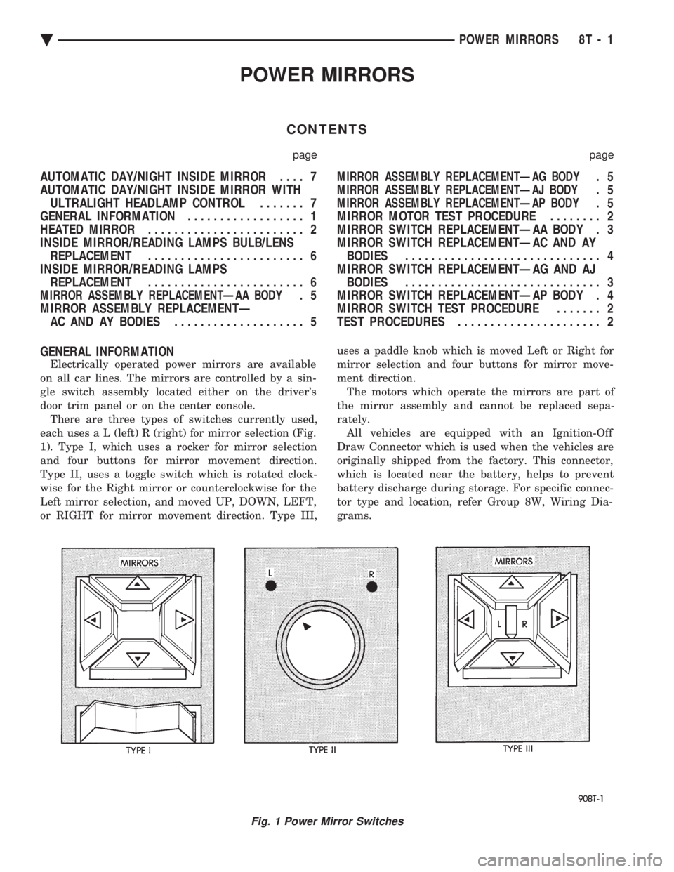
each use s a L (left) R (right) for mirror selection (Fig.
1). Type I, which uses a rocker for mirror selection
and four buttons for mirror movement direction.
Type II, uses a toggle switch which is rotated clock-
wise for the Right mirror or counterclockwise for the
Left mirror selection, and moved UP, DOWN, LEFT,
or RIGHT for mirror movement direction. Type III, uses a paddle knob which is moved Left or Right for
mirror selection and four buttons for mirror move-
ment direction.
The motors which operate the mirrors are part of
the mirror assembly and cannot be replaced sepa-
rately. All vehicles are equipped with an Ignition-Off
Draw Connector which is used when the vehicles are
originally shipped from the factory. This connector,
which is located near the battery, helps to prevent
battery discharge during storage. For specific connec-
tor type and location, refer Group 8W, Wiring Dia-
grams.
Fig. 1 Power Mirror Switches
Ä POWER MIRRORS 8T - 1
Page 749 of 2438

CONDITION: NO TONE WHEN HEADLAMPS ARE ON AND DRIVER'S DOOR IS OPEN, ANDIGNITION IS OFF
PROCEDURE
(1) Check left door jamb switch for good ground
when driver's door is open. This may be checked at
terminal 1 of 25-way body controller connector. (2) Check for battery feed at terminal 16 of 25-way
body controller connector. (3) Check headlamp switch.
CONDITION: NO TONE WHEN KEY IS LEFT INIGNITION AND DRIVER'S DOOR IS OPEN
PROCEDURE
(1) Check left door jamb switch for good ground
when driver's door is open. This may be checked at
terminal 1 of 25-way body controller connector. (2) Check for battery feed at terminal 16 of 25-way
body controller connector. (3) Check key-in switch.
CONDITION: CHIMES CONTINUE WHENHEADLAMPS ARE TURNED OFF AND/OR KEYIS REMOVED FROM IGNITION
PROCEDURE
Check wiring for a grounded condition between
headlamp switch, key-in switch, and body controller.
SERVICE PROCEDURES
CHIME MODULE REPLACEMENT AA and AP
BODIES
(1) Open glove box door and disconnect check strap.
(2) Disconnect glove box light switch.
(3) Remove screws from glove box assembly and
remove. (4) Remove two screws from chime module mount-
ing bracket (Figs. 9 and 10). (5) Disconnect chime module wiring and remove
module. (6) For installation reverse above procedures.
BODY CONTROLLER REPLACEMENT
Refer to Group 8E, Instrument Panel and Gauges.
SEAT BELT BUCKLE REPLACEMENT
Refer to Group 23, Body of this service manual.
HEADLAMP SWITCH REPLACEMENT
Refer to Group 8E, Instrument Panel and Gauges.
KEY-IN SWITCH REPLACEMENT
The Key-in switch is built into the ignition switch as-
sembly. Should the Key-in switch require service, the
ignition switch assembly must be replaced. Refer to
Group 8D Ignition System of this service manual (Fig.
11).
Fig. 9 Chime Module LocationÐAA Body
Fig. 10 Chime Module Location
Fig. 11 Halo Lamp and Key-In Warning Switch Continuity
Ä CHIME WARNING/REMINDER SYSTEM 8U - 5
Page 755 of 2438
When a fusible link blows it is important to find
out what the problem is. They are placed in the sys-
tem for protection against shorts. Which can be
caused by a component failure or wiring failures. Do
not just replace the fusible link to correct the
problem. When diagnosing a faulty fusible link it is impor-
tant to check the wire carefully. In some instances
the link may be blown and it will not show through
the insulation, the wire should be checked over its
entire length for internal breaks. (1) Disconnect battery negative cable.
(2) Cut out the blown portion of the fusible link.
(3) Strip 1 inch of insulation from each end of the
existing fusible link. (4) Place a piece of heat shrink tubing over one
side of the fusible link. Make sure the tubing will be
long enough to cover and seal the entire repair area. (5) Cut a replacement piece of fusible link approx-
imately two inches longer than the piece removed. (6) Remove one inch of insulation from each end of
the replacement fusible link. (7) Spread the strands of wire apart on each of the
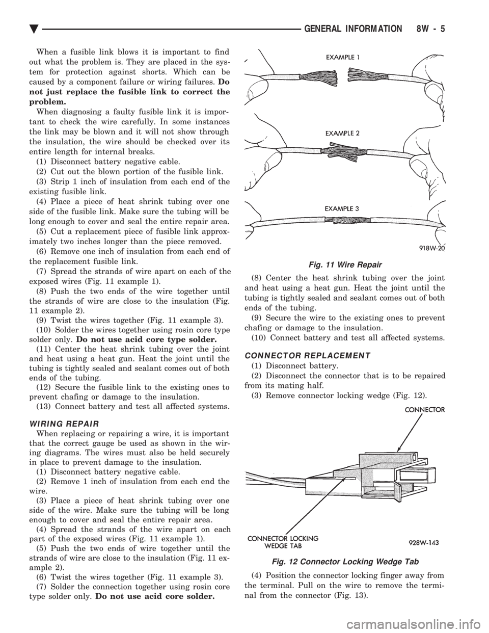
exposed wires (Fig. 11 example 1). (8) Push the two ends of the wire together until
the strands of wire are close to the insulation (Fig.
11 example 2). (9) Twist the wires together (Fig. 11 example 3).
(10) Solder the wires together using rosin core type
solder only. Do not use acid core type solder.
(11) Center the heat shrink tubing over the joint
and heat using a heat gun. Heat the joint until the
tubing is tightly sealed and sealant comes out of both
ends of the tubing. (12) Secure the fusible link to the existing ones to
prevent chafing or damage to the insulation. (13) Connect battery and test all affected systems.
WIRING REPAIR
When replacing or repairing a wire, it is important
that the correct gauge be used as shown in the wir-
ing diagrams. The wires must also be held securely
in place to prevent damage to the insulation. (1) Disconnect battery negative cable.
(2) Remove 1 inch of insulation from each end the
wire. (3) Place a piece of heat shrink tubing over one
side of the wire. Make sure the tubing will be long
enough to cover and seal the entire repair area. (4) Spread the strands of the wire apart on each
part of the exposed wires (Fig. 11 example 1). (5) Push the two ends of wire together until the
strands of wire are close to the insulation (Fig. 11 ex-
ample 2). (6) Twist the wires together (Fig. 11 example 3).
(7) Solder the connection together using rosin core
type solder only. Do not use acid core solder. (8) Center the heat shrink tubing over the joint
and heat using a heat gun. Heat the joint until the
tubing is tightly sealed and sealant comes out of both
ends of the tubing. (9) Secure the wire to the existing ones to prevent
chafing or damage to the insulation. (10) Connect battery and test all affected systems.
CONNECTOR REPLACEMENT
(1) Disconnect battery.
(2) Disconnect the connector that is to be repaired
from its mating half. (3) Remove connector locking wedge (Fig. 12).
(4) Position the connector locking finger away from
the terminal. Pull on the wire to remove the termi-
nal from the connector (Fig. 13).
Fig. 11 Wire Repair
Fig. 12 Connector Locking Wedge Tab
Ä GENERAL INFORMATION 8W - 5