1993 CHEVROLET PLYMOUTH ACCLAIM engine oil
[x] Cancel search: engine oilPage 356 of 2438

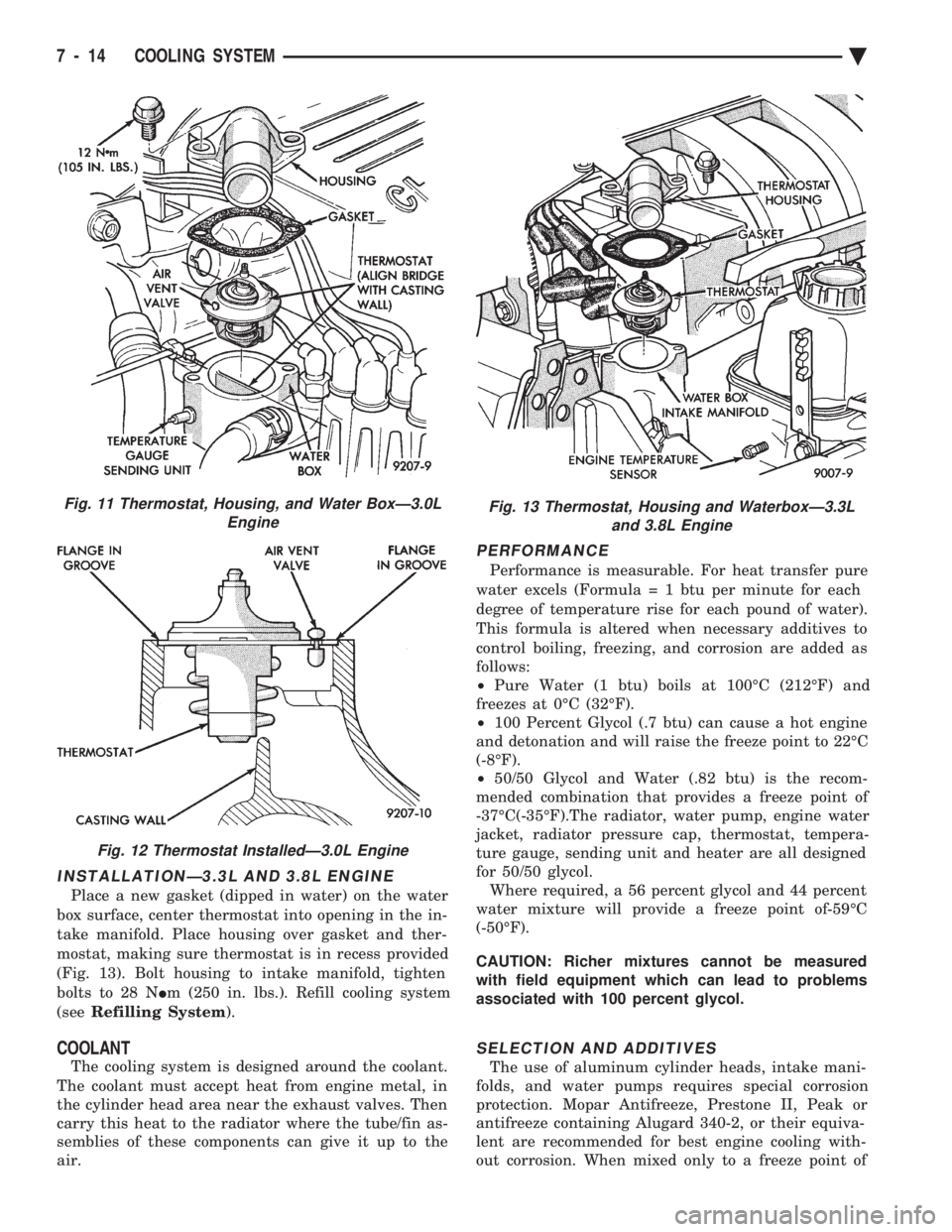
INSTALLATIONÐ3.3L AND 3.8L ENGINE
Place a new gasket (dipped in water) on the water
box surface, center thermostat into opening in the in-
take manifold. Place housing over gasket and ther-
mostat, making sure thermostat is in recess provided
(Fig. 13). Bolt housing to intake manifold, tighten
bolts to 28 N Im (250 in. lbs.). Refill cooling system
(see Refilling System ).
COOLANT
The cooling system is designed around the coolant.
The coolant must accept heat from engine metal, in
the cylinder head area near the exhaust valves. Then
carry this heat to the radiator where the tube/fin as-
semblies of these components can give it up to the
air.
PERFORMANCE
Performance is measurable. For heat transfer pure
water excels (Formul a = 1 btu per minute for each
degree of temperature rise for each pound of water).
This formula is altered when necessary additives to
control boiling, freezing, and corrosion are added as
follows:
² Pure Water (1 btu) boils at 100ÉC (212ÉF) and
freezes at 0ÉC (32ÉF).
² 100 Percent Glycol (.7 btu) can cause a hot engine
and detonation and will raise the freeze point to 22ÉC
(-8ÉF).
² 50/50 Glycol and Water (.82 btu) is the recom-
mended combination that provides a freeze point of
-37ÉC(-35ÉF).The radiator, water pump, engine water
jacket, radiator pressure cap, thermostat, tempera-
ture gauge, sending unit and heater are all designed
for 50/50 glycol. Where required, a 56 percent glycol and 44 percent
water mixture will provide a freeze point of-59ÉC
(-50ÉF).
CAUTION: Richer mixtures cannot be measured
with field equipment which can lead to problems
associated with 100 percent glycol.
SELECTION AND ADDITIVES
The use of aluminum cylinder heads, intake mani-
folds, and water pumps requires special corrosion
protection. Mopar Antifreeze, Prestone II, Peak or
antifreeze containing Alugard 340-2, or their equiva-
lent are recommended for best engine cooling with-
out corrosion. When mixed only to a freeze point of
Fig. 11 Thermostat, Housing, and Water BoxÐ3.0L Engine
Fig. 12 Thermostat InstalledÐ3.0L Engine
Fig. 13 Thermostat, Housing and WaterboxÐ3.3Land 3.8L Engine
7 - 14 COOLING SYSTEM Ä
Page 357 of 2438

-37ÉC (-35ÉF) to -59ÉC (-50ÉF). If it looses color or
becomes contaminated, drain, flush, and replace with
fresh properly mixed solution.
SERVICE
Coolant should be changed at 52,500 miles or three
years, whichever occurs first, then every two years or
30,000 miles.
ROUTINE LEVEL CHECK
Do not remove radiator cap for routine coolant
level inspections. The coolant reserve system provides a quick visual
method for determining the coolant level without re-
moving the radiator cap. Simply observe, with the
engine idling and warmed up to normal operating
temperature, that the level of the coolant in the reserve
tank (Figs. 5 and 6) is between the minimum and
maximum marks.
ADDING ADDITIONAL COOLANT
The radiator cap should not be removed. When
additional coolant is needed to maintain this level, it
should be added to the coolant reserve tank. Use only
50/50 concentration of ethylene glycol type antifreeze
and water.
SERVICE COOLANT LEVEL
The cooling system is closed and designed to main-
tain coolant level to the top of the radiator. When servicing requires a coolant level check in the
radiator, the engine must be offand notunder pres-
sure. Drain several ounces of coolant from the radiator
drain cock while observing the Coolant Recovery Sys-
tem (CRS) Tank. Coolant level in the CRS tank should
drop slightly. Then remove the radiator cap. The radia-
tor should be full to the top. If not, and the coolant level
in the CRS tank is at the MIN mark there is a air leak
in the CRS system. Check hose or hose connections to
the CRS tank, radiator filler neck or the pressure cap
seal to the radiator filler neck for leaks.
LOW COOLANT LEVEL AERATION
Low coolant level in a cross flow radiator will equal-
ize in both tanks with engine off. With engine at
running operating temperature the high pressure inlet
tank runs full and the low pressure outlet tank drops.
If this level drops below the top of the transmission oil
cooler, air will be sucked into the water pump:
² Transmission oil will become hotter.
² High reading shown on the temperature gauge.
² Air in the coolant will also cause loss of flow through
the heater.
² Exhaust gas leaks into the coolant can also cause the
same problems.
DEAERATION
Air can only be removed from the system by gather-
ing under the pressure cap. On the next heat up it will
be pushed past the pressure cap into the CRS tank by
thermal expansion of the coolant. It then escapes to the
atmosphere in the CRS tank and is replaced with solid
coolant on cool down.
COOLING SYSTEM DRAIN, CLEAN, FLUSH AND
REFILL
Drain, flush, and fill the cooling system at the
mileage or time intervals specified in the Maintenance
Schedule in this Group. If the solution is dirty or rusty
or contains a considerable amount of sediment, clean
and flush with a reliable cooling system cleaner. Care
should be taken in disposing of the used engine coolant
from your vehicle. Check governmental regulations for
disposal of used engine coolant.
DRAINING
To drain cooling system move temperature selector
for heater to full heat with engine running (to provide
vacuum for actuation). Without removing radiator
pressure cap and with system not under pres-
sure, Shut engine off and open draincock. The coolant
reserve tank (Fig. 5) should empty first, then remove
radiator pressure cap. (if not, see Testing Cooling
System for leaks). To vent 2.2/2.5L engines remove the
plug above thermostat housing (Fig. 1). For Turbo III
engines remove coolant temperature sensor in the
thermostat housing (Fig. 2). For 3.3L /3.8L engine
remove the engine temperature sending unit (Fig. 3).
Removal of a plug or other component is required
because the thermostat has no air vent and prevents
air flow through it. This allows the coolant to drain
from the engine block.
Fig. 1 Thermostat Housing Drain/Fill PlugÐ2.2/2.5L Engines
Ä COOLING SYSTEM 7 - 15
Page 359 of 2438

TESTING SYSTEM FOR LEAKS
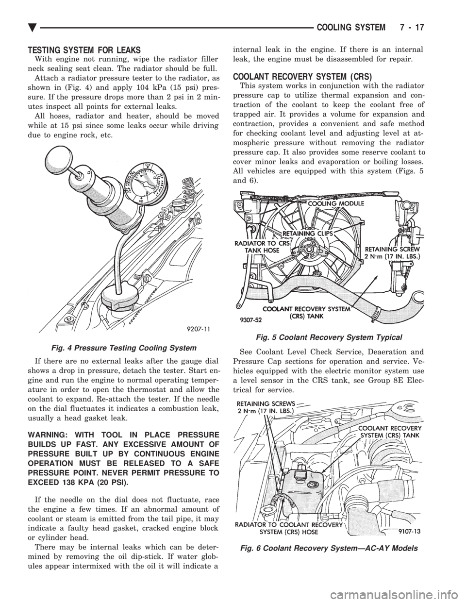
With engine not running, wipe the radiator filler
neck sealing seat clean. The radiator should be full. Attach a radiator pressure tester to the radiator, as
shown in (Fig. 4) and apply 104 kPa (15 psi) pres-
sure. If the pressure drops more than 2 psi in 2 min-
utes inspect all points for external leaks. All hoses, radiator and heater, should be moved
while at 15 psi since some leaks occur while driving
due to engine rock, etc.
If there are no external leaks after the gauge dial
shows a drop in pressure, detach the tester. Start en-
gine and run the engine to normal operating temper-
ature in order to open the thermostat and allow the
coolant to expand. Re-attach the tester. If the needle
on the dial fluctuates it indicates a combustion leak,
usually a head gasket leak.
WARNING: WITH TOOL IN PLACE PRESSURE
BUILDS UP FAST. ANY EXCESSIVE AMOUNT OF
PRESSURE BUILT UP BY CONTINUOUS ENGINE
OPERATION MUST BE RELEASED TO A SAFE
PRESSURE POINT. NEVER PERMIT PRESSURE TO
EXCEED 138 KPA (20 PSI).
If the needle on the dial does not fluctuate, race
the engine a few times. If an abnormal amount of
coolant or steam is emitted from the tail pipe, it may
indicate a faulty head gasket, cracked engine block
or cylinder head. There may be internal leaks which can be deter-
mined by removing the oil dip-stick. If water glob-
ules appear intermixed with the oil it will indicate a internal leak in the engine. If there is an internal
leak, the engine must be disassembled for repair.
COOLANT RECOVERY SYSTEM (CRS)
This system works in conjunction with the radiator
pressure cap to utilize thermal expansion and con-
traction of the coolant to keep the coolant free of
trapped air. It provides a volume for expansion and
contraction, provides a convenient and safe method
for checking coolant level and adjusting level at at-
mospheric pressure without removing the radiator
pressure cap. It also provides some reserve coolant to
cover minor leaks and evaporation or boiling losses.
All vehicles are equipped with this system (Figs. 5
and 6).
See Coolant Level Check Service, Deaeration and
Pressure Cap sections for operation and service. Ve-
hicles equipped with the electric monitor system use
a level sensor in the CRS tank, see Group 8E Elec-
trical for service.
Fig. 4 Pressure Testing Cooling System
Fig. 5 Coolant Recovery System Typical
Fig. 6 Coolant Recovery SystemÐAC-AY Models
Ä COOLING SYSTEM 7 - 17
Page 360 of 2438

RADIATOR PRESSURE CAP
Radiators are equipped with a pressure cap which
releases pressure at some point within a range of
97-124 kPa (14-18 psi) (Fig. 7). The system will operate at higher than atmospheric
pressure which raises the coolant boiling point allow-
ing increased radiator cooling capacity. There is also a vent valve in the center of the cap that
allows a small coolant flow to the CRS tank. If valve is
stuck shut, the radiator hoses will be collapsed
on cool down. Clean the vent valve (Fig. 7) to
ensure proper sealing when boiling point is
reached.
There is also a gasket in the cap to seal to the top of
the filler neck so that vacuum can be maintained for
drawing coolant back into the radiator from the coolant
reserve system tank.
RADIATOR CAP TO FILLER NECK SEAL PRES- SURE RELIEF CHECK
The pressure cap upper gasket (seal) pressure relief
can be checked by removing the overflow hose at the
radiator filler neck nipple (Fig. 7). Attach the Radiator
Pressure Tool to the filler neck nipple and pump air
into the radiator. Pressure cap upper gasket should
relieve at 69-124 kPa (10-18 psi) and hold pressure at
55 kPa (8 psi) minimum.
WARNING: THE WARNING WORDS DO NOT OPEN
HOT ON THE RADIATOR PRESSURE CAP IS A
SAFETY PRECAUTION. WHEN HOT, PRESSURE
BUILDS UP IN COOLING SYSTEM. TO PREVENT
SCALDING OR INJURY, THE RADIATOR CAP
SHOULD NOT BE REMOVED WHILE THE SYSTEM IS
HOT AND/OR UNDER PRESSURE.
There is no need to remove the radiator cap at any
time except for the following purposes:
(1) Check and adjust antifreeze freeze point.
(2) Refill system with new antifreeze.
(3) Conducting service procedures.
(4) Checking for vacuum leaks.
WARNING: IF VEHICLE HAS BEEN RUN RECENTLY,
WAIT 15 MINUTES BEFORE REMOVING CAP. THEN PLACE A SHOP TOWEL OVER THE CAP AND WITH-
OUT PUSHING DOWN ROTATE IT COUNTER-
CLOCKWISE TO THE FIRST STOP. ALLOW FLUIDS
TO ESCAPE THROUGH THE OVERFLOW TUBE AND
WHEN THE SYSTEM STOPS PUSHING COOLANT
AND STEAM INTO THE CRS TANK AND PRESSURE
DROPS PUSH DOWN AND REMOVE THE CAP COM-
PLETELY. SQUEEZING THE RADIATOR INLET HOSE
WITH A SHOP TOWEL (TO CHECK PRESSURE) BE-
FORE AND AFTER TURNING TO THE FIRST STOP IS
RECOMMENDED.
PRESSURE TESTING RADIATOR CAPS
Dip the pressure cap in water, clean any deposits off
the vent valve or its seat and apply cap to end of
Radiator Pressure Tool. Working the plunger, bring the
pressure to 104 kPa (15 psi) on the gauge. If the
pressure cap fails to hold pressure of at least 97 kPa
(14 psi) replace cap. See CAUTION
If the pressure cap tests properly while positioned on
Radiator Pressure Tool, but will not hold pressure or
vacuum when positioned on the radiator. Inspect the
radiator filler neck and cap top gasket for irregularities
that may prevent the cap from sealing properly.
CAUTION: Radiator Pressure Tool is very sensitive to
small air leaks which will not cause cooling system
problems. A pressure cap that does not have a
history of coolant loss should not be replaced just
because it leaks slowly when tested with this tool.
Add water to the tool. Turn tool upside down and
recheck pressure cap to confirm that cap is bad.
INSPECTION
Hold the cap in hand, right side up(Fig. 7). The
vent valve at the bottom of the cap should open. If the
rubber gasket has swollen and prevents the valve from
opening, replace the cap. Hold the cleaned cap in hand upside down.If any
light can be seen between vent valve and rubber
gasket, replace cap. Do not use a replacement cap
that has a spring to hold the vent shut. Replacement cap must be of the type designed for
coolant reserve systems. This design assures coolant
return to radiator.
RADIATORS
The radiators are crossflow types (horizontal tubes)
with design features that provide greater strength as
well as sufficient heat transfer capabilities to keep the
engine satisfactorily cooled.
CAUTION: Plastic tanks, while stronger then brass
are subject to damage by impact, such as wrenches.
Fig. 7 Radiator Pressure Cap Filler Neck
7 - 18 COOLING SYSTEM Ä
Page 365 of 2438

FAN SHROUD
All vehicles have fan shrouds to improve fan air
flow efficiency. These fan shrouds cover less than full
radiator frontal area to prevent the shroud from re-
stricting air flow at high speeds. The shroud supports the electric fan motor and fan.
For removal and installation see Radiator Section.
AUTOMATIC TRANSMISSION OIL COOLERS
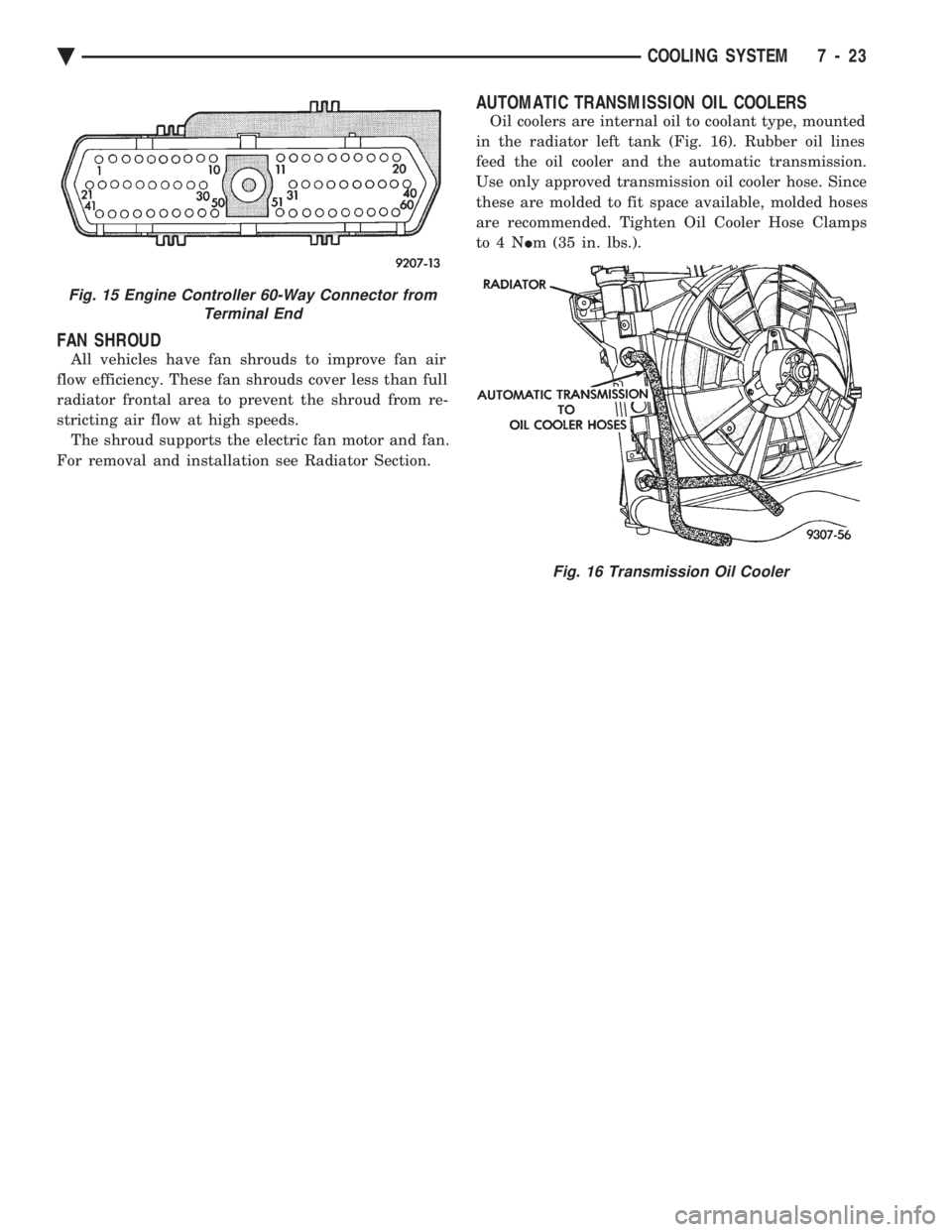
Oil coolers are internal oil to coolant type, mounted
in the radiator left tank (Fig. 16). Rubber oil lines
feed the oil cooler and the automatic transmission.
Use only approved transmission oil cooler hose. Since
these are molded to fit space available, molded hoses
are recommended. Tighten Oil Cooler Hose Clamps
to4N Im (35 in. lbs.).
Fig. 15 Engine Controller 60-Way Connector from
Terminal End
Fig. 16 Transmission Oil Cooler
Ä COOLING SYSTEM 7 - 23
Page 383 of 2438

STARTER TEST PROCEDURES ON VEHICLE INDEX
page page
Diagnostic Preparation ..................... 11
General Information ....................... 11 Starter Control Circuit Tests
................ 15
Starter Feed Circuit Tests .................. 11
GENERAL INFORMATION
The starting system (Fig. 1) has:
² Ignition switch
² Starter relay (Fig. 2)
² Neutral starting and back-up switch with auto-
matic transmissions
² Clutch pedal mounted starter interlock switch
with manual transmissions
² Wiring harness
² Battery
² Starter motor with an integral solenoid
These components form two separate circuits. A
high amperage circuit that feeds the starter motor up
to 300+ amps, and a control circuit that operates on
less than 20 amps.
DIAGNOSTIC PREPARATION
Before going on with starting system diagnostics,
verify: (1) The battery top, posts, and terminals are clean.
(2) The generator drive belt tension and condition
is correct. (3) The battery state-of-charge is correct.
(4) The battery will pass load test.
(5) The battery cable connections at the starter
and engine block are clean and free from corrosion. (6) The wiring harness connectors and terminals
are clean and free from corrosion. (7) Proper circuit grounding.
(8) Refer to Starter System Diagnostics (Fig. 3).
STARTER FEED CIRCUIT TESTS
The following procedure will require a suitable
volt/ampere tester (Fig. 4).
CAUTION: Ignition system also must be disabled to
prevent engine start while performing the following
tests.
(1) Connect a volt-ampere tester (Fig. 4) to the bat-
tery terminals (Fig. 5). Refer to the operating in-
structions provided with the tester being used. (2) Disable ignition system as follows:
² VEHICLES WITH CONVENTIONAL DISTRIBU-
TORS: Disconnect the ignition coil cable from the
distributor cap. Connect a suitable jumper wire be-
tween the coil cable end-terminal and a good body
ground (Fig. 6).
Fig. 1 Starting Components/Wiring
Fig. 2 Starter Relay
Ä BATTERY/STARTING/CHARGING SYSTEMS DIAGNOSTICS 8A - 11
Page 386 of 2438

STARTER FEED CIRCUIT RESISTANCE TEST
Before going on with this operation, review Diag-
nostic Preparation and Starter Feed Circuit Tests.
The following operation will require a voltmeter, ac-
curate to 1/10 of a volt.
CAUTION: Ignition system also must be disabled to
prevent engine start while performing the following
tests.
(1) Disable ignition system as follows:
² VEHICLES WITH CONVENTIONAL DISTRIBU-
TORS: Disconnect the ignition coil cable from the
distributor cap. Connect a suitable jumper wire be-
tween the coil cable end-terminal and a good body
ground (Fig. 6).
² VEHICLES WITH DIRECT IGNITION SYSTEM:
Disconnect the ignition coils electrical connector (Fig.
7). (2) With all wiring harnesses and components
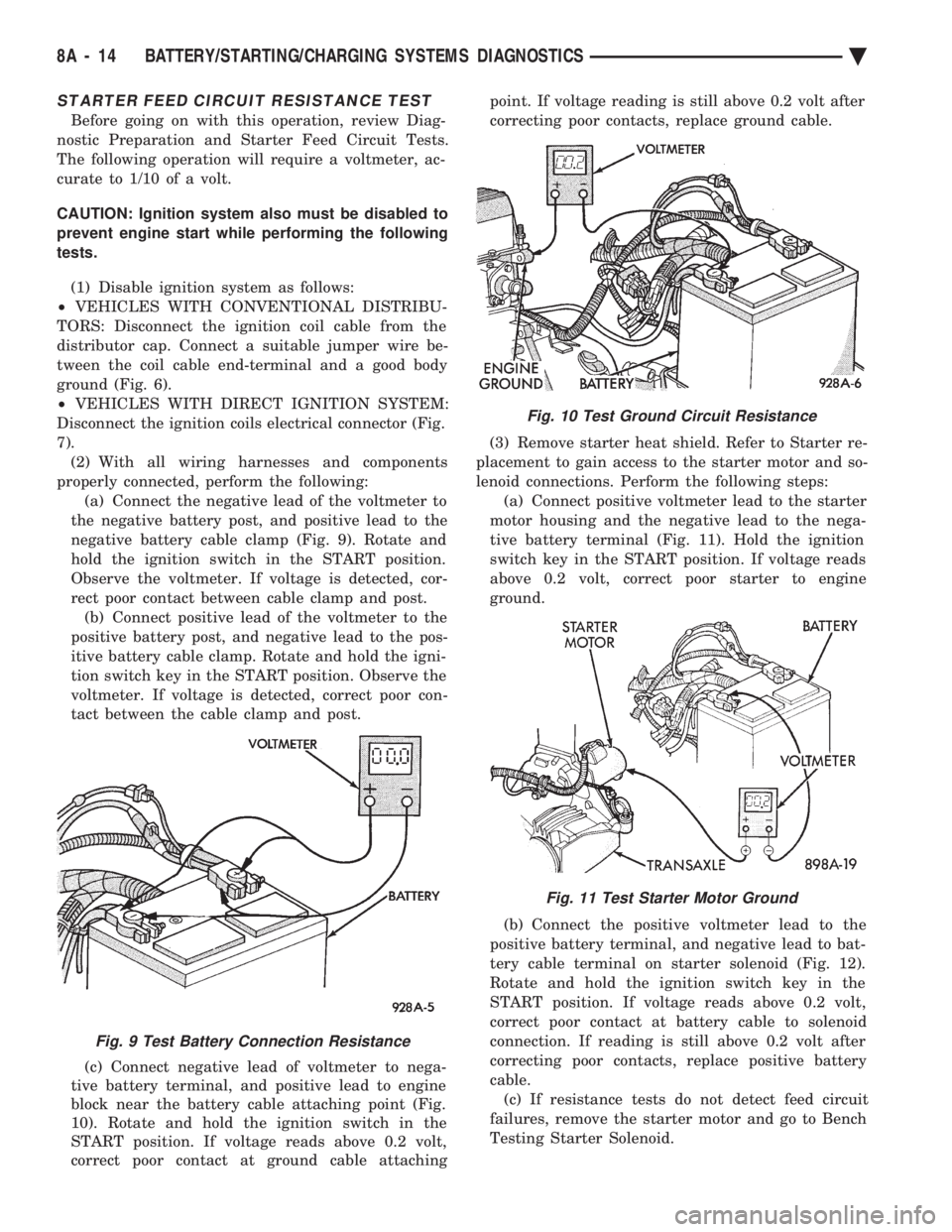
properly connected, perform the following: (a) Connect the negative lead of the voltmeter to
the negative battery post, and positive lead to the
negative battery cable clamp (Fig. 9). Rotate and
hold the ignition switch in the START position.
Observe the voltmeter. If voltage is detected, cor-
rect poor contact between cable clamp and post. (b) Connect positive lead of the voltmeter to the
positive battery post, and negative lead to the pos-
itive battery cable clamp. Rotate and hold the igni-
tion switch key in the START position. Observe the
voltmeter. If voltage is detected, correct poor con-
tact between the cable clamp and post.
(c) Connect negative lead of voltmeter to nega-
tive battery terminal, and positive lead to engine
block near the battery cable attaching point (Fig.
10). Rotate and hold the ignition switch in the
START position. If voltage reads above 0.2 volt,
correct poor contact at ground cable attaching point. If voltage reading is still above 0.2 volt after
correcting poor contacts, replace ground cable.
(3) Remove starter heat shield. Refer to Starter re-
placement to gain access to the starter motor and so-
lenoid connections. Perform the following steps: (a) Connect positive voltmeter lead to the starter
motor housing and the negative lead to the nega-
tive battery terminal (Fig. 11). Hold the ignition
switch key in the START position. If voltage reads
above 0.2 volt, correct poor starter to engine
ground.
(b) Connect the positive voltmeter lead to the
positive battery terminal, and negative lead to bat-
tery cable terminal on starter solenoid (Fig. 12).
Rotate and hold the ignition switch key in the
START position. If voltage reads above 0.2 volt,
correct poor contact at battery cable to solenoid
connection. If reading is still above 0.2 volt after
correcting poor contacts, replace positive battery
cable. (c) If resistance tests do not detect feed circuit
failures, remove the starter motor and go to Bench
Testing Starter Solenoid.
Fig. 9 Test Battery Connection Resistance
Fig. 10 Test Ground Circuit Resistance
Fig. 11 Test Starter Motor Ground
8A - 14 BATTERY/STARTING/CHARGING SYSTEMS DIAGNOSTICS Ä
Page 387 of 2438

STARTER CONTROL CIRCUIT TESTS
The starter control circuit has:
² Starter solenoid
² Starter relay (Fig. 2)
² Neutral starting and back-up switch with auto-
matic transmissions
² Clutch pedal mounted starter interlock switch
with manual transmissions
² Ignition switch
² Battery
² All related wiring and connections
CAUTION: Before performing any starter tests, the
ignition system must be disabled.
² VEHICLES EQUIPPED WITH A CONVEN-
TIONAL DISTRIBUTOR: Disconnect coil wire from
distributor cap center tower. Secure wire to a good
ground to prevent engine from starting (Fig. 6).
² VEHICLES EQUIPPED WITH DIRECT IGNI-
TION SYSTEM: Unplug the coils electrical connector
(Fig. 7).
STARTER SOLENOID TEST
WARNING: CHECK TO ENSURE THAT THE TRANS-
MISSION IS IN PARK OR NEUTRAL WITH THE
PARKING BRAKE APPLIED
(1) Verify battery condition. Battery must be in
good condition with a full charge before performing
any starter tests. Refer to Battery Tests. (2) Perform this starter solenoid test BEFORE per-
forming the starter relay test. (3) Raise the vehicle.
(4) Perform a visual inspection of the starter/
starter solenoid for corrosion, loose connections or
faulty wiring. (5) Lower the vehicle.
(6) Locate the starter relay as follows:
² On AC, AG, AJ and AY Bodies the relay is located
in the Power Distribution Center. This Center is mounted near the front of the left front strut tower
(Fig. 13). The position of the starter relay within this
Center will be shown on the Center cover.
² On AA/AP Bodies the relay is located on the front
of the left front strut tower (Fig. 14).
(7) Remove the starter relay from the connector.
(8) Connect a remote starter switch or a jumper
wire between the battery positive post and terminal
87 on the starter relay connector. To decide the
starter relay terminal numbers, refer to the Starter
Relay Tests.
² If engine now cranks, starter/starter solenoid is
good. Go to the starter relay test.
² If engine does not crank with this test, or solenoid
chatters, check wiring and connectors from starter
Fig. 12 Test Positive Battery Cable Resistance
Fig. 13 Starter Relay LocationÐAC, AG, AJ, and AY Bodies
Fig. 14 Starter Relay LocationÐAA/AP Body
Ä BATTERY/STARTING/CHARGING SYSTEMS DIAGNOSTICS 8A - 15