1993 CHEVROLET PLYMOUTH ACCLAIM airbag
[x] Cancel search: airbagPage 1470 of 2438

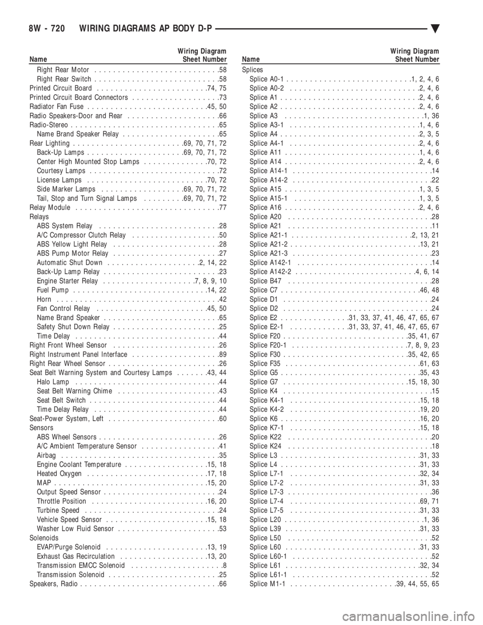
Wiring Diagram
Name Sheet Number
Right Rear Motor ...........................58
Right Rear Switch ...........................58
Printed Circuit Board ....................... .74, 75
Printed Circuit Board Connectors ...................73
Radiator Fan Fuse ......................... .45, 50
Radio Speakers-Door and Rear ....................66
Radio-Stereo ................................65
Name Brand Speaker Relay .....................65
Rear Lighting ....................... .69, 70, 71, 72
Back-Up Lamps .................... .69, 70, 71, 72
Center High Mounted Stop Lamps ..............70, 72
Courtesy Lamps ............................72
License Lamps ......................... .70, 72
Side Marker Lamps ................. .69, 70, 71, 72
Tail, Stop and Turn Signal Lamps .........69, 70, 71, 72
Relay Module ...............................77
Relays ABS System Relay ..........................28
A/C Compressor Clutch Relay ...................50
ABS Yellow Light Relay .......................28
ABS Pump Motor Relay .......................27
Automatic Shut Down ....................2,14,22
Back-Up Lamp Relay .........................23
Engine Starter Relay ....................7,8,9,10
Fuel Pump ............................ .14, 22
Horn ...................................42
Fan Control Relay ....................... .45, 50
Name Brand Speaker .........................65
Safety Shut Down Relay .......................25
Time Delay ...............................44
Right Front Wheel Sensor .......................26
Right Instrument Panel Interface ...................89
Right Rear Wheel Sensor ........................26
Seat Belt Warning System and Courtesy Lamps .......43, 44
Halo Lamp ...............................44
Seat Belt Warning Chime ......................43
Seat Belt Switch ............................44
Time Delay Relay ...........................44
Seat-Power System, Left ........................60
Sensors ABS Wheel Sensors ..........................26
A/C Ambient Temperature Sensor .................41
Airbag ..................................35
Engine Coolant Temperature ..................15, 18
Heated Oxygen ......................... .17, 18
MAP ................................ .15, 20
Output Speed Sensor .........................24
Throttle Position ........................ .16, 20
Turbine Speed .............................24
Vehicle Speed Sensor ..................... .15, 18
Washer Low Fluid Sensor ......................53
Solenoids EVAP/Purge Solenoid ..................... .13, 19
Exhaust Gas Recirculation .................. .13, 20
Transmission EMCC Solenoid ....................8
Transmission Solenoid ........................25
Speakers, Radio ..............................66Wiring Diagram
Name Sheet Number
Splices Splice A0-1 ...........................1,2,4,6
Splice A0-2 ............................2,4,6
Splice A1 ..............................2,4,6
Splice A2 ..............................2,4,6
Splice A3 ..............................1,36
Splice A3-1 ............................1,4,6
Splice A4 ..............................2,3,5
Splice A4-1 ............................2,4,6
Splice A11 .............................1,4,6
Splice A14 .............................2,4,6
Splice A14-1 ..............................14
Splice A14-2 ..............................22
Splice A15 .............................1,3,5
Splice A15-1 ...........................1,3,5
Splice A16 .............................2,4,6
Splice A20 ...............................28
Splice A21 ...............................11
Splice A21-1 ..........................2,13,21
Splice A21-2 ........................... .13, 21
Splice A21-3 ..............................23
Splice A142-1 .............................14
Splice A142-2 ..........................4,6,14
Splice B47 ...............................28
Splice C7 ............................. .46, 48
Splice D1 ................................24
Splice D2 ................................24
Splice E2 .............. .31, 33, 37, 41, 46, 47, 65, 67
Splice E2-1 ............ .31, 33, 37, 41, 46, 47, 65, 67
Splice F20 .......................... .35, 41, 67
Splice F20-1 .........................7,8,9,23
Splice F30 .......................... .35, 42, 65
Splice F35 ............................ .61, 63
Splice G5 ............................. .35, 43
Splice G7 .......................... .15, 18, 30
Splice K4 ................................15
Splice K4-1 ........................... .15, 18
Splice K4-2 ........................... .19, 20
Splice K6 ............................. .16, 20
Splice K7-1 ........................... .15, 18
Splice K22 ...............................20
Splice K24 ...............................18
Splice L3 ............................. .31, 33
Splice L4 ............................. .31, 33
Splice L7-1 ........................... .32, 34
Splice L7-2 ........................... .31, 33
Splice L7-3 ...............................36
Splice L7-4 ........................... .69, 71
Splice L7-5 ........................... .31, 33
Splice L20 ..............................1,36
Splice L39 ............................ .31, 33
Splice L50 ...............................52
Splice L60 ............................ .31, 33
Splice L60-1 ..............................52
Splice L61 ............................ .32, 34
Splice L61-1 ..............................52
Splice M1-1 ...................... .39, 44, 55, 65
8W - 720 WIRING DIAGRAMS AP BODY D-P Ä
Page 2157 of 2438

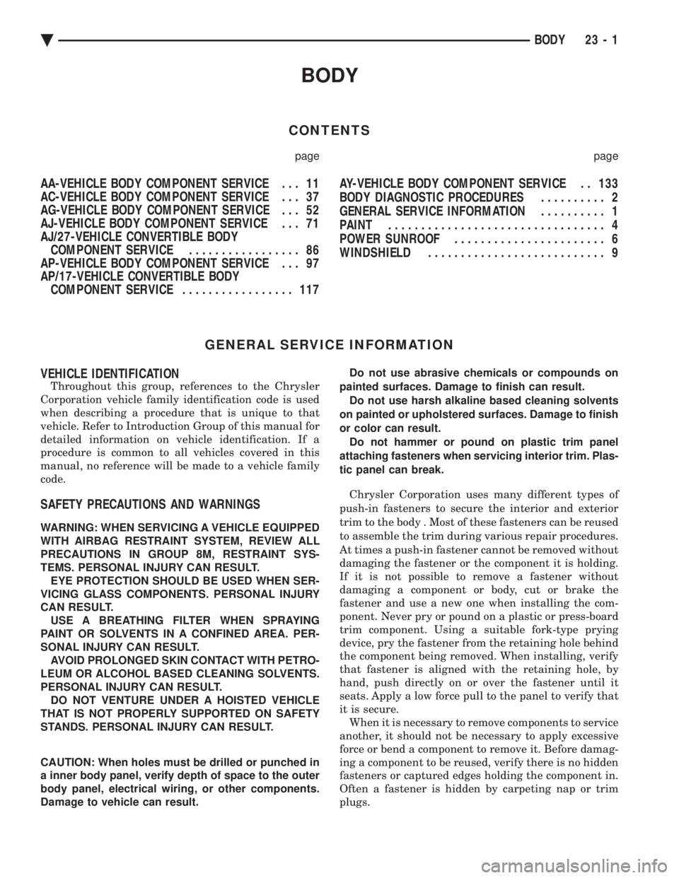
BODY
CONTENTS
page page
AA-VEHICLE BODY COMPONENT SERVICE . . . 11
AC-VEHICLE BODY COMPONENT SERVICE . . . 37
AG-VEHICLE BODY COMPONENT SERVICE . . . 52
AJ-VEHICLE BODY COMPONENT SERVICE . . . 71
AJ/27-VEHICLE CONVERTIBLE BODYCOMPONENT SERVICE ................. 86
AP-VEHICLE BODY COMPONENT SERVICE . . . 97
AP/17-VEHICLE CONVERTIBLE BODY COMPONENT SERVICE ................. 117 AY-VEHICLE BODY COMPONENT SERVICE . . 133
BODY DIAGNOSTIC PROCEDURES .......... 2
GENERAL SERVICE INFORMATION .......... 1
PAINT ................................. 4
POWER SUNROOF ....................... 6
WINDSHIELD ........................... 9
GENERAL SERVICE INFORMATION
VEHICLE IDENTIFICATION
Throughout this group, references to the Chrysler
Corporation vehicle family identification code is used
when describing a procedure that is unique to that
vehicle. Refer to Introduction Group of this manual for
detailed information on vehicle identification. If a
procedure is common to all vehicles covered in this
manual, no reference will be made to a vehicle family
code.
SAFETY PRECAUTIONS AND WARNINGS
WARNING: WHEN SERVICING A VEHICLE EQUIPPED
WITH AIRBAG RESTRAINT SYSTEM, REVIEW ALL
PRECAUTIONS IN GROUP 8M, RESTRAINT SYS-
TEMS. PERSONAL INJURY CAN RESULT. EYE PROTECTION SHOULD BE USED WHEN SER-
VICING GLASS COMPONENTS. PERSONAL INJURY
CAN RESULT. USE A BREATHING FILTER WHEN SPRAYING
PAINT OR SOLVENTS IN A CONFINED AREA. PER-
SONAL INJURY CAN RESULT. AVOID PROLONGED SKIN CONTACT WITH PETRO-
LEUM OR ALCOHOL BASED CLEANING SOLVENTS.
PERSONAL INJURY CAN RESULT. DO NOT VENTURE UNDER A HOISTED VEHICLE
THAT IS NOT PROPERLY SUPPORTED ON SAFETY
STANDS. PERSONAL INJURY CAN RESULT.
CAUTION: When holes must be drilled or punched in
a inner body panel, verify depth of space to the outer
body panel, electrical wiring, or other components.
Damage to vehicle can result. Do not use abrasive chemicals or compounds on
painted surfaces. Damage to finish can result. Do not use harsh alkaline based cleaning solvents
on painted or upholstered surfaces. Damage to finish
or color can result. Do not hammer or pound on plastic trim panel
attaching fasteners when servicing interior trim. Plas-
tic panel can break.
Chrysler Corporation uses many different types of
push-in fasteners to secure the interior and exterior
trim to the body . Most of these fasteners can be reused
to assemble the trim during various repair procedures.
At times a push-in fastener cannot be removed without
damaging the fastener or the component it is holding.
If it is not possible to remove a fastener without
damaging a component or body, cut or brake the
fastener and use a new one when installing the com-
ponent. Never pry or pound on a plastic or press-board
trim component. Using a suitable fork-type prying
device, pry the fastener from the retaining hole behind
the component being removed. When installing, verify
that fastener is aligned with the retaining hole, by
hand, push directly on or over the fastener until it
seats. Apply a low force pull to the panel to verify that
it is secure. When it is necessary to remove components to service
another, it should not be necessary to apply excessive
force or bend a component to remove it. Before damag-
ing a component to be reused, verify there is no hidden
fasteners or captured edges holding the component in.
Often a fastener is hidden by carpeting nap or trim
plugs.
Ä BODY 23 - 1