1993 CHEVROLET PLYMOUTH ACCLAIM wheel size
[x] Cancel search: wheel sizePage 1952 of 2438

(16) Connect the battery ground (negative) cable.
Test the operation of the lights and horns. If applica-
ble, reset the clock and radio.
STEERING COLUMN COMPONENT SERVICE
The Acustar tilt and standard steering columns
(Fig.1) have been designed to be serviced as an as-
sembly; less wiring, switches, shrouds, steering
wheel, etc. Also most steering column components
can be serviced without removing the steering col-
umn from the vehicle. For additional information on
electrical components refer to Group 8H Electrical.
GEAR SHIFT LEVER
The gear shift lever (if equipped) is a serviceable
component of the Acustar steering column assembly.
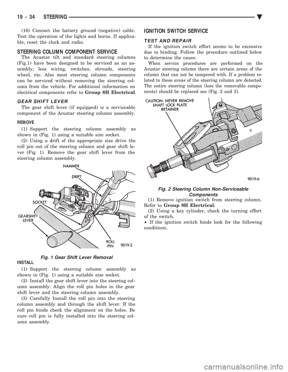
REMOVE (1) Support the steering column assembly as
shown in (Fig. 1) using a suitable size socket. (2) Using a drift of the appropriate size drive the
roll pin out of the steering column and gear shift le-
ver (Fig. 1). Remove the gear shift lever from the
steering column assembly.
INSTALL (1) Support the steering column assembly as
shown in (Fig. 1) using a suitable size socket. (2) Install the gear shift lever into the steering col-
umn assembly. Align the roll pin holes in the gear
shift lever and the steering column assembly. (3) Carefully Install the roll pin into the steering
column assembly and through the shift lever. If the
roll pin binds check the alignment on the holes. Be
sure roll pin is fully installed into the steering col-
umn assembly.
IGNITION SWITCH SERVICE
TEST AND REPAIR
If the ignition switch effort seems to be excessive
due to binding. Follow the procedure outlined below
to determine the cause.
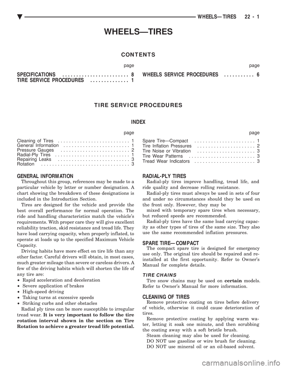
When service procedures are performed on the
Acustar steering column there are certain areas of the
column that can not be tampered with. If a problem re-
lated to these areas of the steering column are detected.
The entire steering column (less the removable compo-
nents) should be replaced see (Fig. 2 and 3).
(1) Remove ignition switch from steering column.
Refer to Group 8H Electrical.
(2) Using a key cylinder, check the turning effort
of the switch.
² If the ignition switch binds look for the following
conditions.
Fig. 1 Gear Shift Lever Removal
Fig. 2 Steering Column Non-Serviceable Components
19 - 34 STEERING Ä
Page 2149 of 2438

WHEELSÐTIRES
CONTENTS
page page
SPECIFICATIONS ........................ 8
TIRE SERVICE PROCEDURES .............. 1 WHEELS SERVICE PROCEDURES
........... 6
TIRE SERVICE PROCEDURES INDEX
page page
Cleaning of Tires .......................... 1
General Information ........................ 1
Pressure Gauges ......................... 2
Radial-Ply Tires ........................... 1
Repairing Leaks .......................... 3
Rotation ................................ 3 Spare TireÐCompact
...................... 1
Tire Inflation Pressures ..................... 2
Tire Noise or Vibration ..................... 3
Tire Wear Patterns ........................ 3
Tread Wear Indicators ...................... 3
GENERAL INFORMATION
Throughout this group, references may be made to a
particular vehicle by letter or number designation. A
chart showing the breakdown of these designations is
included in the Introduction Section. Tires are designed for the vehicle and provide the
best overall performance for normal operation. The
ride and handling characteristics match the vehicle's
requirements. With proper care they will give excellent
reliability traction, skid resistance and tread life. They
have load carrying capacity, when properly inflated, to
operate at loads up to the specified Maximum Vehicle
Capacity. Driving habits have more effect on tire life than any
other factor. Careful drivers will obtain, in most cases,
much greater mileage than severe or careless drivers. A
few of the driving habits which will shorten the life of
any tire are:
² Rapid acceleration and deceleration
² Severe application of brakes
² High-speed driving
² Taking turns at excessive speeds
² Striking curbs and other obstacles
Radial ply tires can be more susceptible to irregular
tread wear. It is very important to follow the tire
rotation interval shown in the section on Tire
Rotation to achieve a greater tread life potential.
RADIAL-PLY TIRES
Radial-ply tires improve handling, tread life, and
ride quality and decrease rolling resistance. Radial-ply tires must always be used in sets of four
and under no circumstances should they be used on
the front only. However, they may be mixed with temporary spare tires when necessary,
but reduced speeds are recommended. Radial-ply tires have the same load carrying capac-
ity as other types of tires of the same size. They also
use the same recommended inflation pressures.
SPARE TIREÐCOMPACT
The compact spare tire is designed for emergency
use only. The original tire should be repaired and re-
installed at the first opportunity. Refer to Owner's
Manual for complete details.
TIRE CHAINS
Tire snow chains may be used on certainmodels.
Refer to Owner's Manual for more information.
CLEANING OF TIRES
Remove protective coating on tires before delivery
of vehicle, otherwise it could cause deterioration of
tires. Remove protective coating by applying warm wa-
ter, letting it soak one minute, and then scrubbing
the coating away with a soft bristle brush. Steam cleaning may also be used for cleaning.
DO NOT use gasoline or wire brush for cleaning.
DO NOT use mineral oil or an oil-based solvent.
Ä WHEELSÐTIRES 22 - 1
Page 2150 of 2438

PRESSURE GAUGES
High quality dial type air pressure gauges are rec-
ommended. After checking pressure with the gauge,
replace valve caps and tighten finger tight.
TIRE INFLATION PRESSURES
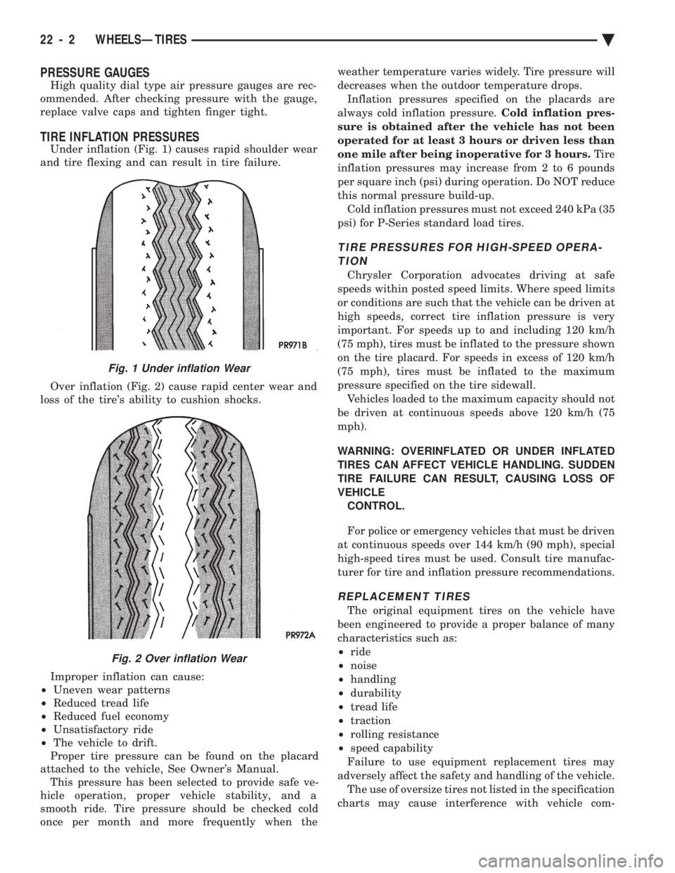
Under inflation (Fig. 1) causes rapid shoulder wear
and tire flexing and can result in tire failure.
Over inflation (Fig. 2) cause rapid center wear and
loss of the tire's ability to cushion shocks.
Improper inflation can cause:
² Uneven wear patterns
² Reduced tread life
² Reduced fuel economy
² Unsatisfactory ride
² The vehicle to drift.
Proper tire pressure can be found on the placard
attached to the vehicle, See Owner's Manual. This pressure has been selected to provide safe ve-
hicle operation, proper vehicle stability, and a
smooth ride. Tire pressure should be checked cold
once per month and more frequently when the weather temperature varies widely. Tire pressure will
decreases when the outdoor temperature drops.
Inflation pressures specified on the placards are
always cold inflation pressure. Cold inflation pres-
sure is obtained after the vehicle has not been
operated for at least 3 hours or driven less than
one mile after being inoperative for 3 hours. Tire
inflation pressures may increase from 2 to 6 pounds
per square inch (psi) during operation. Do NOT reduce
this normal pressure build-up. Cold inflation pressures must not exceed 240 kPa (35
psi) for P-Series standard load tires.
TIRE PRESSURES FOR HIGH-SPEED OPERA- TION
Chrysler Corporation advocates driving at safe
speeds within posted speed limits. Where speed limits
or conditions are such that the vehicle can be driven at
high speeds, correct tire inflation pressure is very
important. For speeds up to and including 120 km/h
(75 mph), tires must be inflated to the pressure shown
on the tire placard. For speeds in excess of 120 km/h
(75 mph), tires must be inflated to the maximum
pressure specified on the tire sidewall. Vehicles loaded to the maximum capacity should not
be driven at continuous speeds above 120 km/h (75
mph).
WARNING: OVERINFLATED OR UNDER INFLATED
TIRES CAN AFFECT VEHICLE HANDLING. SUDDEN
TIRE FAILURE CAN RESULT, CAUSING LOSS OF
VEHICLE CONTROL.
For police or emergency vehicles that must be driven
at continuous speeds over 144 km/h (90 mph), special
high-speed tires must be used. Consult tire manufac-
turer for tire and inflation pressure recommendations.
REPLACEMENT TIRES
The original equipment tires on the vehicle have
been engineered to provide a proper balance of many
characteristics such as:
² ride
² noise
² handling
² durability
² tread life
² traction
² rolling resistance
² speed capability
Failure to use equipment replacement tires may
adversely affect the safety and handling of the vehicle. The use of oversize tires not listed in the specification
charts may cause interference with vehicle com-
Fig. 1 Under inflation Wear
Fig. 2 Over inflation Wear
22 - 2 WHEELSÐTIRES Ä