1993 CHEVROLET PLYMOUTH ACCLAIM steering wheel adjustment
[x] Cancel search: steering wheel adjustmentPage 1635 of 2438

LEFT SIDE MOUNT
(1) Raise vehicle on hoist and remove left front
wheel. (2) Remove inter splash shield.
(3) Support the transmission with a transmission
jack. (4) Remove the insulator thru bolt from the mount.
(5) Remove the transmission mount fasteners and
remove mount. (6) Reverse removal procedure for installation. En-
sure that the slide tube is seated into the rail
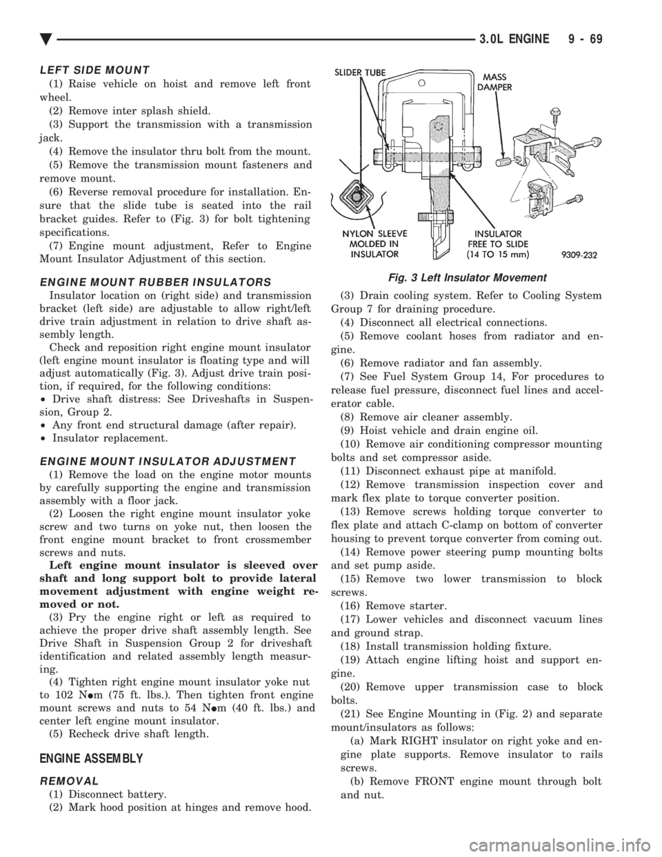
bracket guides. Refer to (Fig. 3) for bolt tightening
specifications. (7) Engine mount adjustment, Refer to Engine
Mount Insulator Adjustment of this section.
ENGINE MOUNT RUBBER INSULATORS
Insulator location on (right side) and transmission
bracket (left side) are adjustable to allow right/left
drive train adjustment in relation to drive shaft as-
sembly length. Check and reposition right engine mount insulator
(left engine mount insulator is floating type and will
adjust automatically (Fig. 3). Adjust drive train posi-
tion, if required, for the following conditions:
² Drive shaft distress: See Driveshafts in Suspen-
sion, Group 2.
² Any front end structural damage (after repair).
² Insulator replacement.
ENGINE MOUNT INSULATOR ADJUSTMENT
(1) Remove the load on the engine motor mounts
by carefully supporting the engine and transmission
assembly with a floor jack. (2) Loosen the right engine mount insulator yoke
screw and two turns on yoke nut, then loosen the
front engine mount bracket to front crossmember
screws and nuts. Left engine mount insulator is sleeved over
shaft and long support bolt to provide lateral
movement adjustment with engine weight re-
moved or not. (3) Pry the engine right or left as required to
achieve the proper drive shaft assembly length. See
Drive Shaft in Suspension Group 2 for driveshaft
identification and related assembly length measur-
ing. (4) Tighten right engine mount insulator yoke nut
to 102 N Im (75 ft. lbs.). Then tighten front engine
mount screws and nuts to 54 N Im (40 ft. lbs.) and
center left engine mount insulator. (5) Recheck drive shaft length.
ENGINE ASSEMBLY
REMOVAL
(1) Disconnect battery.
(2) Mark hood position at hinges and remove hood. (3) Drain cooling system. Refer to Cooling System
Group 7 for draining procedure. (4) Disconnect all electrical connections.
(5) Remove coolant hoses from radiator and en-
gine. (6) Remove radiator and fan assembly.
(7) See Fuel System Group 14, For procedures to
release fuel pressure, disconnect fuel lines and accel-
erator cable. (8) Remove air cleaner assembly.
(9) Hoist vehicle and drain engine oil.
(10) Remove air conditioning compressor mounting
bolts and set compressor aside. (11) Disconnect exhaust pipe at manifold.
(12) Remove transmission inspection cover and
mark flex plate to torque converter position. (13) Remove screws holding torque converter to
flex plate and attach C-clamp on bottom of converter
housing to prevent torque converter from coming out. (14) Remove power steering pump mounting bolts
and set pump aside. (15) Remove two lower transmission to block
screws. (16) Remove starter.
(17) Lower vehicles and disconnect vacuum lines
and ground strap. (18) Install transmission holding fixture.
(19) Attach engine lifting hoist and support en-
gine. (20) Remove upper transmission case to block
bolts. (21) See Engine Mounting in (Fig. 2) and separate
mount/insulators as follows: (a) Mark RIGHT insulator on right yoke and en-
gine plate supports. Remove insulator to rails
screws. (b) Remove FRONT engine mount through bolt
and nut.
Fig. 3 Left Insulator Movement
Ä 3.0L ENGINE 9 - 69
Page 1667 of 2438

(2) Loosen the right engine mount insulator yoke
screw and 2 turns on yoke nut, then loosen the front
engine mount bracket to front crossmember screws and
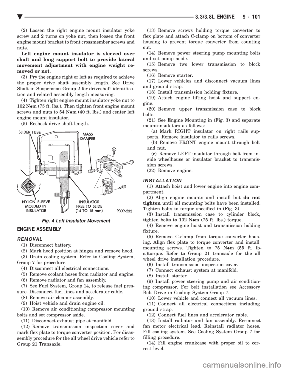
nuts. Left engine mount insulator is sleeved over
shaft and long support bolt to provide lateral
movement adjustment with engine weight re-
moved or not. (3) Pry the engine right or left as required to achieve
the proper drive shaft assembly length. See Drive
Shaft in Suspension Group 2 for driveshaft identifica-
tion and related assembly length measuring. (4) Tighten right engine mount insulator yoke nut to
102 N Im (75 ft. lbs.). Then tighten front engine mount
screws and nuts to 54 N Im (40 ft. lbs.) and center left
engine mount insulator. (5) Recheck drive shaft length.
ENGINE ASSEMBLY
REMOVAL
(1) Disconnect battery.
(2) Mark hood position at hinges and remove hood.
(3) Drain cooling system. Refer to Cooling System,
Group 7 for procedure. (4) Disconnect all electrical connections.
(5) Remove coolant hoses from radiator and engine.
(6) Remove radiator and fan assembly.
(7) See Fuel System, Group 14, to release fuel pres-
sure. Disconnect fuel lines and accelerator cable. (8) Remove air cleaner assembly.
(9) Hoist vehicle and drain engine oil.
(10) Remove air conditioning compressor mounting
bolts and set compressor aside. (11) Disconnect exhaust pipe at manifold.
(12) Remove transmission inspection cover and
mark flex plate to torque converter position. For disas-
sembly procedure for the all wheel drive vehicle refer to
Group 21 Transaxle. (13) Remove screws holding torque converter to
flex plate and attach C-clamp on bottom of converter
housing to prevent torque converter from counting
out. (14) Remove power steering pump mounting bolts
and set pump aside. (15) Remove two lower transmission to block
screws. (16) Remove starter.
(17) Lower vehicles and disconnect vacuum lines
and ground strap. (18) Install transmission holding fixture.
(19) Attach engine lifting hoist and support en-
gine. (20) Remove upper transmission case to block
bolts. (21) See Engine Mounting in (Fig. 3) and separate
mount/insulators as follows: (a) Mark RIGHT insulator on right rails sup-
ports. Remove insulator to rails screws. (b) Remove FRONT engine mount through bolt
and nut. (c) Remove LEFT insulator through bolt from in-
side wheelhouse or insulator bracket to transmis-
sion screws.
(22) Remove engine.
INSTALLATION
(1) Attach hoist and lower engine into engine com-
partment. (2) Align engine mounts and install but do not
tighten until all mounting bolts have been installed.
Tighten bolts to torque specified in (Fig. 3). (3) Install transmission case to cylinder block,
tighten bolts to 102 N Im (75 ft. lbs.) torque.
(4) Remove engine hoist and transmission holding
fixture. (5) Remove C-clamp from torque converter hous-
ing. Align flex plate to torque converter and install
mounting screws. Tighten to 75 N Im (55 ft. lb-
s.)torque. Refer to Group 21 transaxle for the all
wheel drive installation procedure. (6) Install transmission inspection cover.
(7) Connect exhaust system at manifold.
(8) Install starter.
(9) Install power steering pump and air condition-
ing compressor. For belt installation see Accessory
Belt Drive in Cooling System Group 7. (10) Lower vehicle and connect all vacuum lines.
(11) Connect all electrical connections including
ground strap. (12) Connect fuel lines and accelerator cable.
(13) Install radiator and fan assembly. Reconnect
fan motor electrical lead. Reinstall radiator hoses.
Fill cooling system. See Cooling System Group 7 for
filling procedure. (14) Fill engine crankcase with proper oil to cor-
rect level.
Fig. 4 Left Insulator Movement
Ä 3.3/3.8L ENGINE 9 - 101
Page 1945 of 2438

bolts and nut on locating stud (Fig. 2). The right rear
crossmember stud is a pilot that correctly locates
the crossmember. Tighten down this bolt first,
then torque all 4 crossmember fasteners to 122
N Im (90 ft. lbs.).
CAUTION: Proper torque on the crossmember to
frame rail mounting bolts is very important.
(3) Torque the 4 bolts (Fig. 3) attaching the steering
gear assembly to front crossmember, to 68 N Im (50 ft.
lbs.). To ensure proper alignment of the steering
gear tighten left front bolt first. (4) Attach the engine damper strut from the engine
to the crossmember (if so equipped). (5) Attach the fluid tubes (Fig. 3) from the power
steering pump to the fittings on the steering gear.
Torque the fluid pressure line to steering gear tube nut
to 31 N Im (275 in. lbs.).
(6) Mount the outer tie rod ends to the steering
knuckles. Install the tie rod end to steering knuckle
attaching nuts. Torque the tie rod end to steering
knuckle nuts to 52 N Im (38 ft. lbs.). Install cotter pin
in tie rod end. (7) Install the front tire and wheel assemblies on
vehicle. Install the wheel lug nuts and torque to 129
N Im (95 ft. lbs.).
(8) Lower vehicle.
CAUTION: Do not use automatic transmission fluid. (9) Fill power steering pump fluid reservoir to the
(Full-Cold) proper level. (10) Start the engine and let run for a few seconds.
Then turn the engine off.
(11) Add fluid if necessary.
(12) Raise front wheels of vehicle off the ground.
(13) Start engine and turn steering wheel several
times from stop to stop to bleed air from fluid in
system. Stop engine, check fluid level, and inspect
system for leaks. Fill pump reservoir to correct
level with Mopar t, Power Steering Fluid, or
equivalent. See Checking Fluid Level.
(14) Lower front wheels of vehicle back on the
ground. (15) Adjust toe (Refer to Group 2 Suspension).
OUTER TIE ROD
REMOVAL
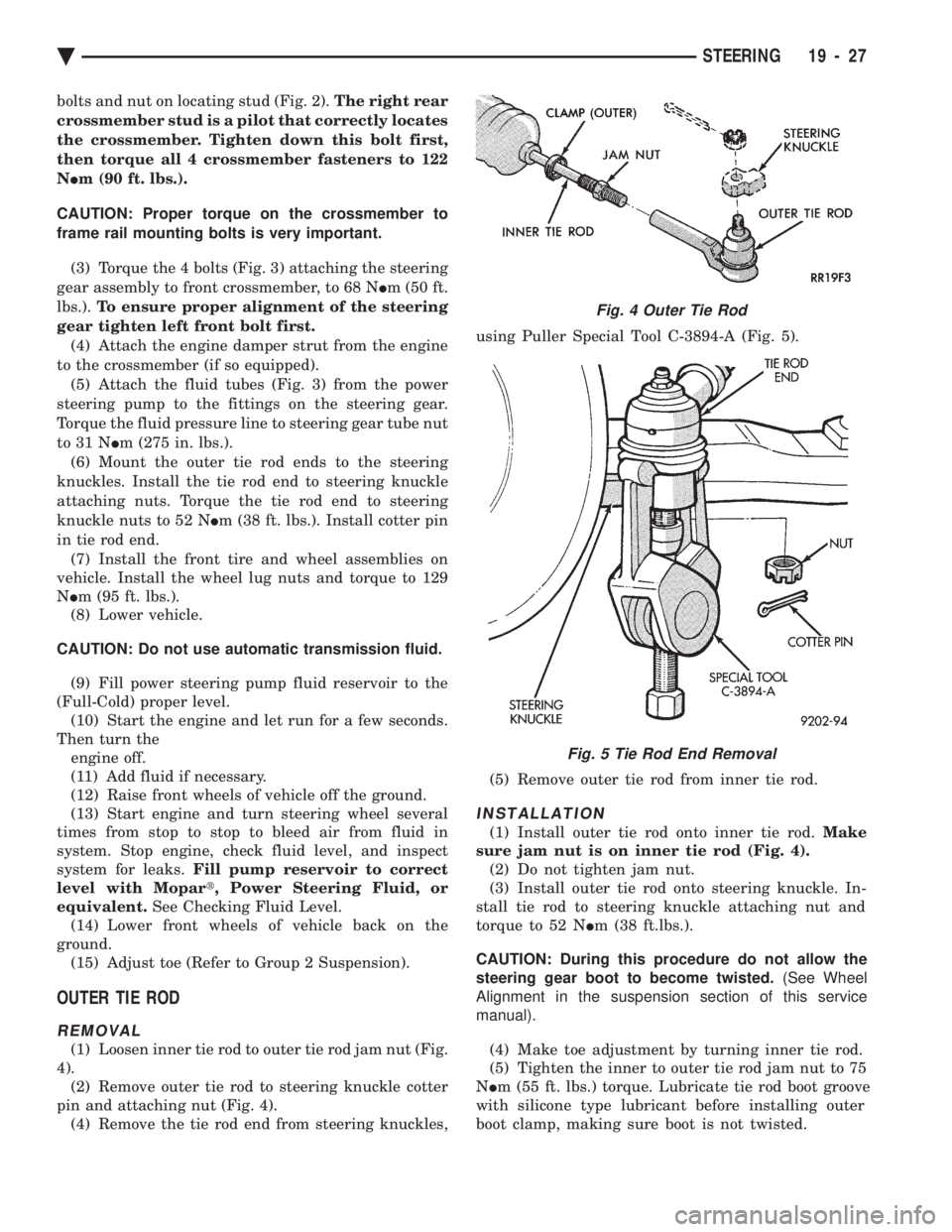
(1) Loosen inner tie rod to outer tie rod jam nut (Fig.
4). (2) Remove outer tie rod to steering knuckle cotter
pin and attaching nut (Fig. 4). (4) Remove the tie rod end from steering knuckles, using Puller Special Tool C-3894-A (Fig. 5).
(5) Remove outer tie rod from inner tie rod.
INSTALLATION
(1) Install outer tie rod onto inner tie rod. Make
sure jam nut is on inner tie rod (Fig. 4). (2) Do not tighten jam nut.
(3) Install outer tie rod onto steering knuckle. In-
stall tie rod to steering knuckle attaching nut and
torque to 52 N Im (38 ft.lbs.).
CAUTION: During this procedure do not allow the
steering gear boot to become twisted. (See Wheel
Alignment in the suspension section of this service
manual).
(4) Make toe adjustment by turning inner tie rod.
(5) Tighten the inner to outer tie rod jam nut to 75
N Im (55 ft. lbs.) torque. Lubricate tie rod boot groove
with silicone type lubricant before installing outer
boot clamp, making sure boot is not twisted.
Fig. 4 Outer Tie Rod
Fig. 5 Tie Rod End Removal
Ä STEERING 19 - 27
Page 1951 of 2438

(3) Position the steering column assembly in the
vehicle. Align the steering column assembly mounting
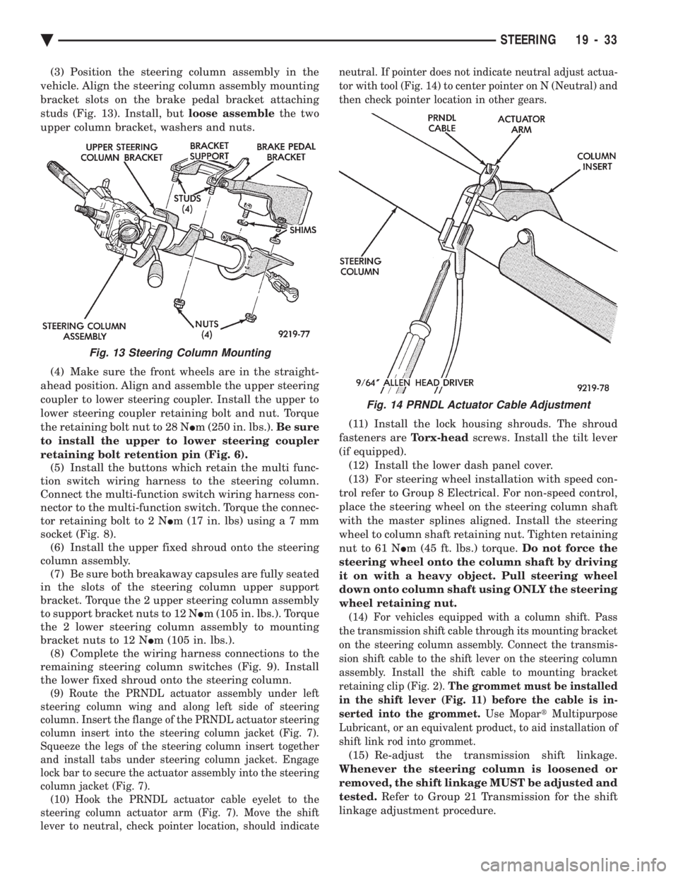
bracket slots on the brake pedal bracket attaching
studs (Fig. 13). Install, but loose assemblethe two
upper column bracket, washers and nuts.
(4) Make sure the front wheels are in the straight-
ahead position. Align and assemble the upper steering
coupler to lower steering coupler. Install the upper to
lower steering coupler retaining bolt and nut. Torque
the retaining bolt nut to 28 N Im (250 in. lbs.). Be sure
to install the upper to lower steering coupler
retaining bolt retention pin (Fig. 6). (5) Install the buttons which retain the multi func-
tion switch wiring harness to the steering column.
Connect the multi-function switch wiring harness con-
nector to the multi-function switch. Torque the connec-
tor retaining bolt to 2 N Im (17 in. lbs) usin ga7mm
socket (Fig. 8). (6) Install the upper fixed shroud onto the steering
column assembly. (7) Be sure both breakaway capsules are fully seated
in the slots of the steering column upper support
bracket. Torque the 2 upper steering column assembly
to support bracket nuts to 12 N Im (105 in. lbs.). Torque
the 2 lower steering column assembly to mounting
bracket nuts to 12 N Im (105 in. lbs.).
(8) Complete the wiring harness connections to the
remaining steering column switches (Fig. 9). Install
the lower fixed shroud onto the steering column.
(9) Route the PRNDL actuator assembly under left
steering column wing and along left side of steering
column. Insert the flange of the PRNDL actuator steering
column insert into the steering column jacket (Fig. 7).
Squeeze the legs of the steering column insert together
and install tabs under steering column jacket. Engage
lock bar to secure the actuator assembly into the steering
column jacket (Fig. 7). (10) Hook the PRNDL actuator cable eyelet to the
steering column actuator arm (Fig. 7). Move the shift
lever to neutral, check pointer location, should indicate neutral. If pointer does not indicate neutral adjust actua-
tor with tool (Fig. 14) to center pointer on N (Neutral) and
then check pointer location in other gears.
(11) Install the lock housing shrouds. The shroud
fasteners are Torx-headscrews. Install the tilt lever
(if equipped). (12) Install the lower dash panel cover.
(13) For steering wheel installation with speed con-
trol refer to Group 8 Electrical. For non-speed control,
place the steering wheel on the steering column shaft
with the master splines aligned. Install the steering
wheel to column shaft retaining nut. Tighten retaining
nut to 61 N Im (45 ft. lbs.) torque. Do not force the
steering wheel onto the column shaft by driving
it on with a heavy object. Pull steering wheel
down onto column shaft using ONLY the steering
wheel retaining nut.
(14) For vehicles equipped with a column shift. Pass
the transmission shift cable through its mounting bracket
on the steering column assembly. Connect the transmis-
sion shift cable to the shift lever on the steering column
assembly. Install the shift cable to mounting bracket
retaining clip (Fig. 2). The grommet must be installed
in the shift lever (Fig. 11) before the cable is in-
serted into the grommet. Use MopartMultipurpose
Lubricant, or an equivalent product, to aid installation of
shift link rod into grommet.
(15) Re-adjust the transmission shift linkage.
Whenever the steering column is loosened or
removed, the shift linkage MUST be adjusted and
tested. Refer to Group 21 Transmission for the shift
linkage adjustment procedure.
Fig. 13 Steering Column Mounting
Fig. 14 PRNDL Actuator Cable Adjustment
Ä STEERING 19 - 33