1993 CHEVROLET PLYMOUTH ACCLAIM oil dipstick
[x] Cancel search: oil dipstickPage 1674 of 2438
(15) Install rocker arm covers tighten screws to 14
N Im (120 in. lbs.) and connector to ignition coils.
(16) Install Intake Manifold; Refer to Intake Mani-
fold Installation 3.3/3.8L Engine, Group 11 Exhaust
System and Intake Manifold.
HYDRAULIC TAPPETS
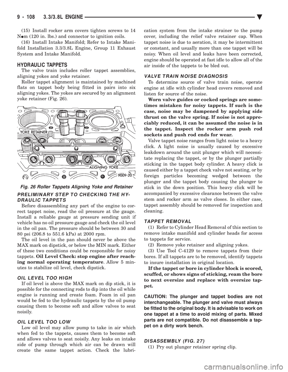
The valve train includes roller tappet assemblies,
aligning yokes and yoke retainer. Roller tappet alignment is maintained by machined
flats on tappet body being fitted in pairs into six
aligning yokes. The yokes are secured by an alignment
yoke retainer (Fig. 26).
PRELIMINARY STEP TO CHECKING THE HY- DRAULIC TAPPETS
Before disassembling any part of the engine to cor-
rect tappet noise, read the oil pressure at the gauge.
Install a reliable gauge at pressure sending unit if
vehicle has no oil pressure gauge and check the oil level
in the oil pan. The pressure should be between 30 and
80 psi (206.8 to 551.6 kPa) at 2000 rpm. The oil level in the pan should never be above the
MAX mark on dipstick, or below the MIN mark. Either
of these two conditions could be responsible for noisy
tappets. Oil Level Check: stop engine after reach-
ing normal operating temperature . Allow 5 min-
utes to stabilize oil level, check dipstick.
OIL LEVEL TOO HIGH
If oil level is above the MAX mark on dip stick, it is
possible for the connecting rods to dip into the oil while
engine is running and create foam. Foam in oil pan
would be fed to the hydraulic tappets by the oil pump
causing them to become soft and allow valves to seat
noisily.
OIL LEVEL TOO LOW
Low oil level may allow pump to take in air which
when fed to the tappets, causes them to become soft
and allows valves to seat noisily. Any leaks on intake
side of pump through which air can be drawn will
create the same tappet action. Check the lubri- cation system from the intake strainer to the pump
cover, including the relief valve retainer cap. When
tappet noise is due to aeration, it may be intermittent
or constant, and usually more than one tappet will be
noisy. When oil level and leaks have been corrected,
engine should be operated at fast idle to allow all of the
air inside of the tappets to be bled out.
VALVE TRAIN NOISE DIAGNOSIS
To determine source of valve train noise, operate
engine at idle with cylinder head covers removed and
listen for source of the noise. Worn valve guides or cocked springs are some-
times mistaken for noisy tappets. If such is the
case, noise may be dampened by applying side
thrust on the valve spring. If noise is not appre-
ciably reduced, it can be assumed the noise is in
the tappet. Inspect the rocker arm push rod
sockets and push rod ends for wear. Valve tappet noise ranges from light noise to a heavy
click. A light noise is usually caused by excessive
leakdown around the unit plunger which will necessi-
tate replacing the tappet, or by the plunger partially
sticking in the tappet body cylinder. A heavy click is
caused either by a tappet check valve not seating, or by
foreign particles becoming wedged between the
plunger and the tappet body causing the plunger to
stick in the down position. This heavy click will be
accompanied by excessive clearance between the valve
stem and rocker arm as valve closes. In either case,
tappet assembly should be removed for inspection and
cleaning.
TAPPET REMOVAL
(1) Refer to Cylinder Head Removal of this section to
remove intake manifold and cylinder heads for access
to tappets for service. (2) Remove yoke retainer and aligning yokes.
(3) Use Tool C-4129 to remove tappets from their
bores. If all tappets are to be removed, identify tappets
to insure installation in original location. If the tappet or bore in cylinder block is scored,
scuffed, or shows signs of sticking, ream the bore
to next oversize and replace with oversize tap-
pet.
CAUTION: The plunger and tappet bodies are not
interchangeable. The plunger and valve must always
be fitted to the original body. It is advisable to work on
one tappet at a time to avoid mixing of parts. Mixed
parts are not compatible. Do not disassemble a tap-
pet on a dirty work bench.
DISASSEMBLY (FIG. 27)
(1) Pry out plunger retainer spring clip.
Fig. 26 Roller Tappets Aligning Yoke and Retainer
9 - 108 3.3/3.8L ENGINE Ä
Page 1688 of 2438
ENGINE LUBRICATION SYSTEM
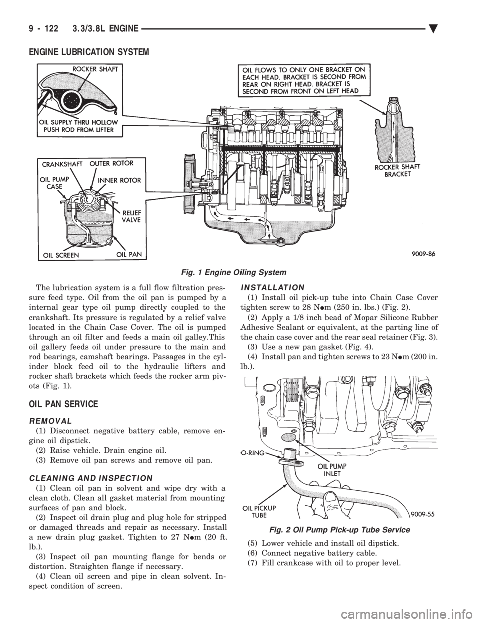
The lubrication system is a full flow filtration pres-
sure feed type. Oil from the oil pan is pumped by a
internal gear type oil pump directly coupled to the
crankshaft. Its pressure is regulated by a relief valve
located in the Chain Case Cover. The oil is pumped
through an oil filter and feeds a main oil galley.This
oil gallery feeds oil under pressure to the main and
rod bearings, camshaft bearings. Passages in the cyl-
inder block feed oil to the hydraulic lifters and
rocker shaft brackets which feeds the rocker arm piv-
ots (Fig. 1).
OIL PAN SERVICE
REMOVAL
(1) Disconnect negative battery cable, remove en-
gine oil dipstick. (2) Raise vehicle. Drain engine oil.
(3) Remove oil pan screws and remove oil pan.
CLEANING AND INSPECTION
(1) Clean oil pan in solvent and wipe dry with a
clean cloth. Clean all gasket material from mounting
surfaces of pan and block. (2) Inspect oil drain plug and plug hole for stripped
or damaged threads and repair as necessary. Install
a new drain plug gasket. Tighten to 27 N Im (20 ft.
lb.). (3) Inspect oil pan mounting flange for bends or
distortion. Straighten flange if necessary. (4) Clean oil screen and pipe in clean solvent. In-
spect condition of screen.
INSTALLATION
(1) Install oil pick-up tube into Chain Case Cover
tighten screw to 28 N Im (250 in. lbs.) (Fig. 2).
(2) Apply a 1/8 inch bead of Mopar Silicone Rubber
Adhesive Sealant or equivalent, at the parting line of
the chain case cover and the rear seal retainer (Fig. 3). (3) Use a new pan gasket (Fig. 4).
(4) Install pan and tighten screws to 23 N Im (200 in.
lb.).
(5) Lower vehicle and install oil dipstick.
(6) Connect negative battery cable.
(7) Fill crankcase with oil to proper level.
Fig. 1 Engine Oiling System
Fig. 2 Oil Pump Pick-up Tube Service
9 - 122 3.3/3.8L ENGINE Ä
Page 1920 of 2438
cle and or engine application the Saginaw T/C style
power steering pump is used on, it will be equipped
with a plastic integral or remote mounted power
steering fluid reservoir. Drive tangs on the power steering gear pinion, mate
loosely with the stub shaft of the steering gear. This
will allow manual steering control to be maintained, if
the drive belt on the power steering pump should
break. However, under these conditions, steering effort
will significantly increase.
STEERING COMPONENTS SERVICE DIAGNOSIS
POWER STEERING PUMP SERVICE
The service procedures for the Saginaw power steer-
ing pump are limited to the areas and components
listed below. No repair procedures are to be done
on internal components of the Saginaw power
steering pumps.
² Repair of power steering fluid leaks from areas of
the power steering pump sealed by O-rings is allowed
(See Pump Leak Diagnosis). However power steering
pump shaft seal leakage will require replacement of
the pump.
² Power steering fluid reservoirs, related components
and attaching hardware.
² Power steering fluid reservoir filler cap/dipstick as-
semblies. Because of unique shaft bearings, flow control levels
or pump displacements, power steering pumps may be
used only on specific vehicle applications. Be sure that
all power steering pumps are only replaced with a
pump that is the correct replacement for that specific
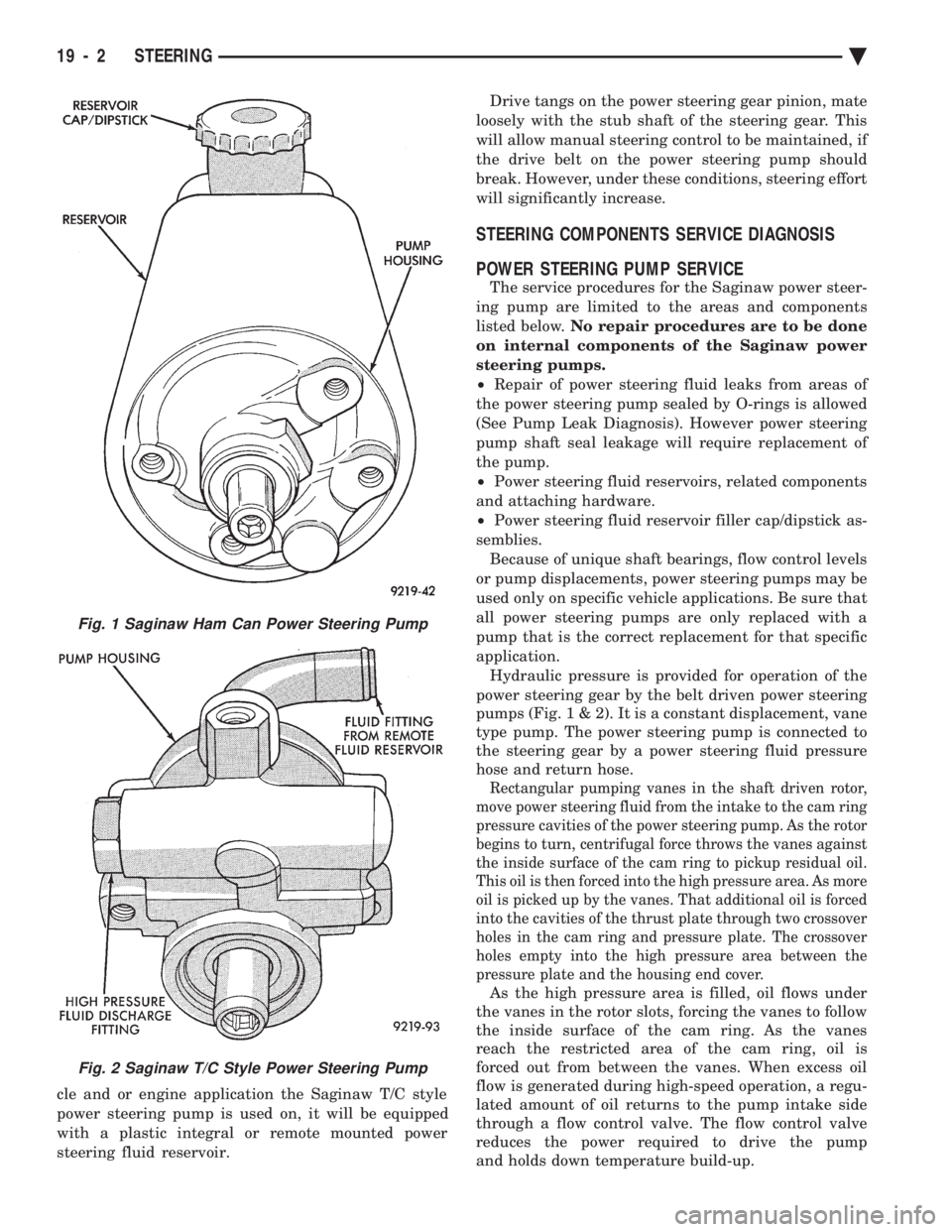
application. Hydraulic pressure is provided for operation of the
power steering gear by the belt driven power steering
pumps (Fig . 1 & 2). It is a constant displacement, vane
type pump. The power steering pump is connected to
the steering gear by a power steering fluid pressure
hose and return hose.
Rectangular pumping vanes in the shaft driven rotor,
move power steering fluid from the intake to the cam ring
pressure cavities of the power steering pump. As the rotor
begins to turn, centrifugal force throws the vanes against
the inside surface of the cam ring to pickup residual oil.
This oil is then forced into the high pressure area. As more
oil is picked up by the vanes. That additional oil is forced
into the cavities of the thrust plate through two crossover
holes in the cam ring and pressure plate. The crossover
holes empty into the high pressure area between the
pressure plate and the housing end cover.
As the high pressure area is filled, oil flows under
the vanes in the rotor slots, forcing the vanes to follow
the inside surface of the cam ring. As the vanes
reach the restricted area of the cam ring, oil is
forced out from between the vanes. When excess oil
flow is generated during high-speed operation, a regu-
lated amount of oil returns to the pump intake side
through a flow control valve. The flow control valve
reduces the power required to drive the pump
and holds down temperature build-up.
Fig. 1 Saginaw Ham Can Power Steering Pump
Fig. 2 Saginaw T/C Style Power Steering Pump
19 - 2 STEERING Ä
Page 1927 of 2438
When steering conditions exceed maximum pres-
sure requirements, such as when the wheels are
turned against the stops. The pressure built up in
the steering gear exerts pressure on the spring end of
the flow control valve. The high pressure lifts the re-
lief valve ball from its seat and allows oil to flow
through a trigger orifice located in the outlet fitting.
This reduces pressure on the spring end of the flow
control valve which then opens and allows the oil to
return to the intake side of the pump. This action
limits maximum pressure output of the pump to a
safe level. Under normal power steering pump operating con-
ditions, pressure requirements of the pump are below
maximum, causing the pressure relief valve to re-
main closed.
CHECKING POWER STEERING FLUID LEVEL
WARNING: FLUID LEVEL SHOULD BE CHECKED
WITH ENGINE OFF TO PREVENT INJURY FROM
MOVING PARTS. DO NOT USE AUTOMATIC TRANS-
MISSION FLUID IN THE POWER STEERING SYS-
TEM. DO NOT OVERFILL THE POWER STEERING
SYSTEM.
Wipe reservoir filler cap free of dirt, before check-
ing power steering fluid level. The dipstick should in- dicate FULL COLD when fluid is at normal ambient
temperature, approximately 21ÉC to 27ÉC (70ÉF to
80ÉF). In all pumps add fluid as necessary to obtain
proper level, using only MopartPower Steering
Fluid, or equivalent. DO NOT USE ANY TYPE
OF AUTOMATIC TRANSMISSION FLUID.
POWER STEERING PUMP PRESSURE TEST
The following procedure can be used to test the op-
eration of the power steering system on the vehicle. (1) Check power steering pump drive belt tension
and adjust as necessary. (2) Disconnect power steering fluid pressure hose,
at steering gear or power steering pump. Use a con-
tainer for dripping fluid. (3) Connect Pressure Gauge, Special Tool C-3309-E
(Fig. 1) to both hoses using adapter fittings. Connect
spare pressure hose to gear or pump. (4) Completely open valve on Special Tool
C-3309-E (Fig. 1). (5) Start engine and let idle.
(6) Check power steering fluid level, and add fluid
as necessary. (7) Gauge should read below 862 kPa (125 psi), if
above, inspect the hoses for restrictions and repair as
necessary. The initial pressure should be in the
range of 345-552 kPa (50-80 psi).
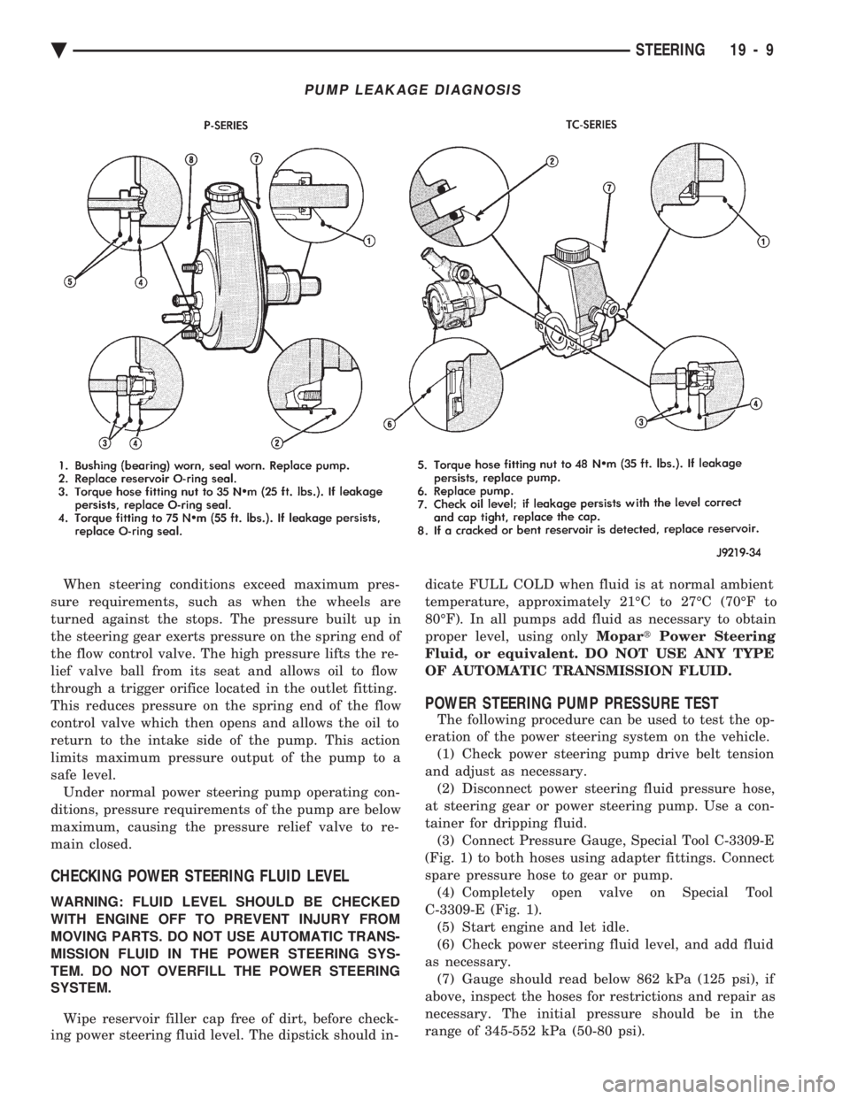
PUMP LEAKAGE DIAGNOSIS
Ä STEERING 19 - 9
Page 1932 of 2438
(10) Connect negative cable back on negative post
of battery. (11) Start engine and turn steering wheel several
times from stop to stop to bleed air from fluid in sys-
tem. Stop engine, check fluid level, and inspect sys-
tem for leaks. See Checking Fluid Level.
3.0 LITER
REMOVE
(1) REMOVE THE (-) NEGATIVE BATTERY CA-
BLE FROM THE BATTERY AND ISOLATE CA-
BLE. (2) Remove the serpentine accessory drive belt
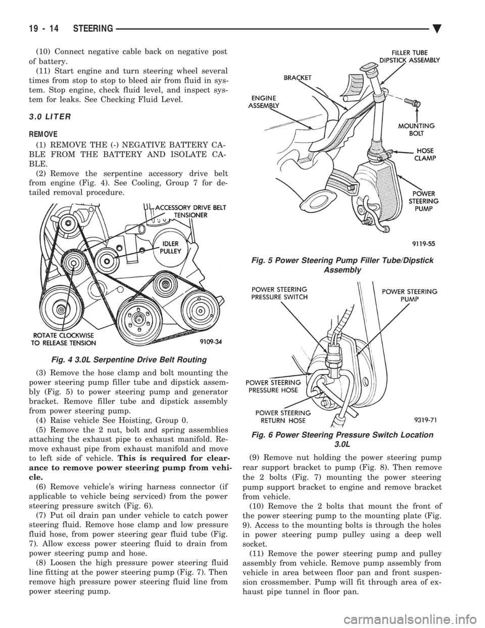
from engine (Fig. 4). See Cooling, Group 7 for de-
tailed removal procedure.
(3) Remove the hose clamp and bolt mounting the
power steering pump filler tube and dipstick assem-
bly (Fig. 5) to power steering pump and generator
bracket. Remove filler tube and dipstick assembly
from power steering pump. (4) Raise vehicle See Hoisting, Group 0.
(5) Remove the 2 nut, bolt and spring assemblies
attaching the exhaust pipe to exhaust manifold. Re-
move exhaust pipe from exhaust manifold and move
to left side of vehicle. This is required for clear-
ance to remove power steering pump from vehi-
cle. (6) Remove vehicle's wiring harness connector (if
applicable to vehicle being serviced) from the power
steering pressure switch (Fig. 6). (7) Put oil drain pan under vehicle to catch power
steering fluid. Remove hose clamp and low pressure
fluid hose, from power steering gear fluid tube (Fig.
7). Allow excess power steering fluid to drain from
power steering pump and hose. (8) Loosen the high pressure power steering fluid
line fitting at the power steering pump (Fig. 7). Then
remove high pressure power steering fluid line from
power steering pump. (9) Remove nut holding the power steering pump
rear support bracket to pump (Fig. 8). Then remove
the 2 bolts (Fig. 7) mounting the power steering
pump support bracket to engine and remove bracket
from vehicle. (10) Remove the 2 bolts that mount the front of
the power steering pump to the mounting plate (Fig.
9). Access to the mounting bolts is through the holes
in power steering pump pulley using a deep well
socket. (11) Remove the power steering pump and pulley
assembly from vehicle. Remove pump assembly from
vehicle in area between floor pan and front suspen-
sion crossmember. Pump will fit through area of ex-
haust pipe tunnel in floor pan.
Fig. 4 3.0L Serpentine Drive Belt Routing
Fig. 5 Power Steering Pump Filler Tube/Dipstick Assembly
Fig. 6 Power Steering Pressure Switch Location 3.0L
19 - 14 STEERING Ä
Page 1995 of 2438
THREE SPEED TORQUEFLITE AUTOMATIC TRANSAXLE INDEX
page page
Accumulator-Recondition ................... 67
Aluminum Thread Repair ................... 48
Assembly Subassembly Installation ........... 57
Band Adjustment ......................... 47
Bearing Adjustment Procedures .............. 81
Clutch and Servo Air Pressure Tests .......... 43
Differential Repair ........................ 76
Disassembly Subassembly Removal .......... 50
Fluid and Filter Change .................... 40
Fluid Drain and Refill ..................... 40
Fluid Leakage-Transaxle Torque Converter Housing Area .......................... 44
Fluid Level and Condition .................. 40
Front Clutch-Recondition ................... 62
Front Planetary & Annulus Gear-Recondition .... 65
Gearshift Linkage Adjustment ............... 46
General Information ....................... 35
Governor ............................... 48
Hydraulic Control Pressure Adjustments ....... 47
Hydraulic Pressure Tests ................... 42
Kickdown Servo (Controlled Load)-Recondition . . 67 Low/Reverse Servo-Recondition
.............. 66
Oil Cooler Flow Check .................... 48
Oil Coolers and Tubes Reverse Flushing ...... 48
Oil Pump-Recondition ..................... 62
Output Shaft Repair ...................... 71
Park/Neutral Position and Back-Up Lamp Switch . 47
Parking Pawl ............................ 71
Pump Oil Seal-Replacement ................ 61
Rear Clutch-Recondition ................... 64
Road Test .............................. 40
Selection of Lubricant ..................... 40
Special Additives ......................... 40
Three Speed Torqueflite General Diagnosis ..... 36
Throttle Pressure Linkage Adjustment ......... 46
Torque Converter Clutch Solenoid Wiring Connector ............................ 40
Transaxle and Torque Converter Removal ...... 48
Transfer Shaft Repair ..................... 68
Valve Body-Recondition .................... 57
Vehicle Speed Sensor Pinion Gear ........... 47
GENERAL INFORMATION
Safety goggles should be worn at all times
when working on these transaxles. This transaxle combines a fully automatic 3 speed
transmission, final drive gearing, and differential into
a front wheel drive system. The unit is a Metric
design. The identification markings and usage of the
transaxle are charted in Diagnosis and Tests. Transaxle operation requirements are differ-
ent for each vehicle and engine combination and
some internal parts will be different to provide
for this. Therefore, when replacing parts, refer to
the seven digit part number stamped on rear of
the transaxle oil pan flange. Within this transaxle, there are 3 primary areas:
(1) Main center line plus valve body.
(2) Transfer shaft center line (includes governor and
parking sprag). (3) Differential center line. Center distances be-
tween the main rotating parts in these 3 areas are held
precise. This maintains a low noise level through
smooth accurate mesh of the gears. The torque converter, transaxle area, and differential
are housed in an integral aluminum die casting. The
differential oil sump is common with thetransaxle
sump. Separate filling of the differential is NOT nec-
essary. The torque converter is attached to the crankshaft
through a flexible driving plate. Cooling of the con-
verter is accomplished by circulating the transaxle
fluid through an oil-to-water type cooler located in the
radiator side tank and/or an oil-to air heat ex- changer. The torque converter assembly is a sealed
unit that cannot be disassembled.
The transaxle fluid is filtered by an internal filter
attached to the lower side of the valve body assem-
bly. Engine torque is transmitted to the torque con-
verter then, through the input shaft to multiple-disc
clutches in the transaxle. The power flow depends on
the application of the clutches and bands. Refer to
Elements in Use Chart in Diagnosis and Tests sec-
tion. The transaxle consists of two multiple-disc
clutches, an overrunning clutch, two servos, a hy-
draulic accumulator, two bands, and two planetary
gear sets. They provide three forward ratios and a re-
verse ratio. The common sun gear of the planetary
gear sets is connected to the front clutch by a driving
shell. The drive shell is splined to the sun gear and
to the front clutch retainer. The hydraulic system
consists of an oil pump, and a single valve body
which contains all of the valves except the governor
valves. The transaxle sump and differential sump are
both vented through the dipstick.Output torque
from the main center line is delivered through heli-
cal gears to the transfer shaft.This gear set is a
factor of the final drive (axle) ratio. The shaft also
carries the governor and parking sprag. An integral
helical gear on the transfer shaft drives the differen-
tial ring gear. The final drive gearing is completed
with one of three gear sets producing overall top gear
ratios of 2.78, 3.02, or 3.22 depending on model and
application.
Ä TRANSAXLE 21 - 35
Page 2000 of 2438
FLUID LEVEL AND CONDITION
The transmission and differential sump have a
common oil sump with a communicating opening
between the two. Before removing the dipstick, wipe all dirt off of the
protective disc and the dipstick handle. The torque converter will fill in both the PPark or N
Neutral positions. Place the selector lever in PPark to
check fluid level. Inspect fluid level on dipstick every six months.
Allow the engine to idle for at least one minute
with vehicle on level ground. This will assure
complete oil level stabilization between differen-
tial and transmission. A properly filled transaxle
will read near the addmark when fluid temperature is
21 degrees Celsius (70 degrees Fahrenheit). When the
transaxle reaches operating temperature the fluid
should be in the HOTregion.
Low fluid level can cause a variety of conditions
because it allows the pump to take in air along with the
fluid. As in any hydraulic system, air bubbles make the
fluid spongy, therefore, pressures will be low and build
up slowly. Improper filling can also raise the fluid level too
high. When the transaxle has too much fluid, the gears
churn up foam and cause the same conditions which
occur with a low fluid level. In either case, the air bubbles can cause overheating,
fluid oxidation, and varnishing, which can interfere
with normal valve, clutch, and servo operation. Foam-
ing can also result in fluid escaping from the transaxle
vent (dipstick handle) where it may be mistaken for a
leak. Along with fluid level, it is important to check the
condition of the fluid. When the fluid smells burned,
and is contaminated with metal or friction material
particles, a complete transaxle overhaul is needed. Be
sure to examine the fluid on the dipstick closely. If
there is any doubt about its condition, drain out a
sample for a double check. After the fluid has been checked, seat the dipstick
fully to seal out water and dirt.
SELECTION OF LUBRICANT
It is important that the proper lubricant be used in
these transmissions. MOPAR tATF PLUS (Automatic
Transmission Fluid-Type 7176) should be used to aid in
assuring optimum transmission performance. Fluids of
the type labeled DEXRON II Automatic Transmission
Fluid should be used only if the recommended fluid is
not available. It is important that the transmission
fluid be maintained at the prescribed level using the
recommended fluids.
SPECIAL ADDITIVES
Chrysler Corporation does not recommend the addi-
tion of any fluids to the transmission, other than the
automatic transmission fluid listed above. An ex- ception to this policy is the use of special dyes to aid in
detecting fluid leaks. The use of transmission sealers
should be avoided, since they may adversely affect
seals.
FLUID AND FILTER CHANGE
When the factory fill fluid is changed, only
fluids of the type labeled MOPAR tATF PLUS
(Automatic Transmission fluid) Type 7176 should
be used. A band adjustment and filter change
should be made at the time of the oil change. The
magnet (on the inside of the oil pan) should also
be cleaned with a clean, dry cloth. If the transaxle is disassembled for any reason,
the fluid and filter should be changed, and the
band(s) adjusted.
FLUID DRAIN AND REFILL
(1) Raise vehicle on a hoist (See Lubrication, Group
0). Place a drain container with a large opening, under
transaxle oil pan. (2) Loosen pan bolts and tap the pan at one corner to
break it loose allowing fluid to drain, then remove the
oil pan. (3) Install a new filter and gasket on bottom of the
valve body and tighten retaining screws to 5 N Im (40
in. lbs.). (4) Clean the oil pan and magnet. Reinstall pan
using new MOPAR tAdhesive sealant. Tighten oil pan
bolts to 19 N Im (165 in. lbs.).
(5) Pour four quarts of MOPAR tATF PLUS (Auto-
matic Transmission Fluid) Type 7176 through the
dipstick opening. (6) Start engine and allow to idle for at least one
minute. Then, with parking and service brakes ap-
plied, move selector lever momentarily to each posi-
tion, ending in the park or neutral position. (7) Add sufficient fluid to bring level to 1/8 inch
below the ADD mark. Recheck fluid level after transaxle is at normal
operating temperature. The level should be in the HOT
region (Fig. 1). To prevent dirt from entering transaxle, make cer-
tain that dipstick is full seated into the dipstick open-
ing.
TORQUE CONVERTER CLUTCH SOLENOID WIRING
CONNECTOR
If wiring connector is unplugged, the torque con-
verter clutch will not operate (Fig. 2).
ROAD TEST
Prior to performing a road test, be certain that the
fluid level and condition, and control cable adjustments
have been checked and approved. During the road test, the transaxle should be oper-
ated in each position to check for slipping and any
variation in shifting.
21 - 40 TRANSAXLE Ä
Page 2004 of 2438
clutch is operating. Hold air pressure on for a few
seconds and inspect system for excessive oil leaks.
REAR CLUTCH
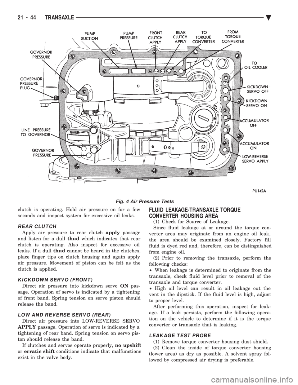
Apply air pressure to rear clutch applypassage
and listen for a dull thudwhich indicates that rear
clutch is operating. Also inspect for excessive oil
leaks. If a dull thudcannot be heard in the clutches,
place finger tips on clutch housing and again apply
air pressure. Movement of piston can be felt as the
clutch is applied.
KICKDOWN SERVO (FRONT)
Direct air pressure into kickdown servo ONpas-
sage. Operation of servo is indicated by a tightening
of front band. Spring tension on servo piston should
release the band.
LOW AND REVERSE SERVO (REAR)
Direct air pressure into LOW-REVERSE SERVO
APPLY passage. Operation of servo is indicated by a
tightening of rear band. Spring tension on servo pis-
ton should release the band. If clutches and servos operate properly, no upshift
or erratic shift conditions indicate that malfunctions
exist in the valve body.
FLUID LEAKAGE-TRANSAXLE TORQUE
CONVERTER HOUSING AREA
(1) Check for Source of Leakage.
Since fluid leakage at or around the torque con-
verter area may originate from an engine oil leak,
the area should be examined closely. Factory fill
fluid is dyed red and, therefore, can be distinguished
from engine oil. (2) Prior to removing the transaxle, perform the
following checks:
² When leakage is determined to originate from the
transaxle, check fluid level prior to removal of the
transaxle and torque converter.
² High oil level can result in oil leakage out the
vent in the dipstick. If the fluid level is high, adjust
to proper level. After performing this operation, inspect for leak-
age. If a leak persists, perform the following opera-
tion on the vehicle to determine if it is the torque
converter or transaxle that is leaking.
LEAKAGE TEST PROBE
(1) Remove torque converter housing dust shield.
(2) Clean the inside of torque converter housing
(lower area) as dry as possible. A solvent spray fol-
lowed by compressed air drying is preferable.
Fig. 4 Air Pressure Tests
21 - 44 TRANSAXLE Ä