1993 CHEVROLET PLYMOUTH ACCLAIM key
[x] Cancel search: keyPage 1467 of 2438
WIRING DIAGRAMS AP BODY D-P
ALPHABETICAL INDEX
Wiring Diagram
Name Sheet Number
ABS Hydraulic Modulator Unit .....................27
ABS Pump Motor Relay .........................27
ABS System Controller ................... .26, 27, 28
ABS System Relay ............................28
ABS Yellow Light Relay .........................28
A/C and Heater System ..................... .47, 48
A/C Cycling Switch ..........................48
A/C High Pressure Switch ......................48
A/C Low Pressure Switch ......................48
Blower Motor ..............................47
Blower Switch .............................47
Defrost Switch .............................47
Illumination Lamp ...........................47
Resistor .................................48
A/C Compressor Clutch Relay .....................50
Airbag Diagnostic Module Connector ................78
Airbag System ...............................35
Clockspring ...............................35
Diagnostic Module ..........................35
Sensors .................................35
Squibb (Airbag Igniter) ........................35
Anti-Lock Braking System ..................26, 27, 28
Data Link Connector .........................27
Hydraulic Modulator Unit ......................27
Pump Motor Relay ..........................27
System Controller ..................... .26, 27, 28
System Relay ..............................28
Wheel Sensors .............................26
Yellow Light Relay ..........................28
Anti-Lock Brake System Controller Connector ...........90
Ash Receiver Lamp ...........................37
Automatic Shut Down Relay 2.2L E.F.I. .............2,14
Automatic Shut Down Relay 2.5L E.F.I. .............2,14
Automatic Shut Down Relay 3.0L .................2,22
Back-Up Lamp Relay ..........................23
Back-Up Lamp Switch .......................7,8,9
Battery .................................1,3,5
Brake Warning Lamp Switch ......................11
Body to Instrument Panel Wiring Left ................87
Cargo Lamp ................................40
Center High Mounted Stop Lamp ................70, 72
Charging System .........................3,4,5,6
Battery .................................3,5
Generator ...............................4,6
Ignition Off Draw Connector ...................3,5
Chime, Key-In, Seat Belt Warning, Headlamp On .........43
Cigar Lighter ................................37
Cigar Lighter Lamp ............................37
Circuit Breakers Headlamp Switch ...........................36
Cavity #8 ..........................2,11,57,58
Cavity #11 ..............................1,60Wiring Diagram
Name Sheet Number
Clockspring .......................... .29, 35, 42
Clutch Pedal Position Jumper ...................8,10
Clutch Pedal Position Switch .....................7,9
Courtesy Lamps .............................72
Data Link Connector ..................... .13, 22, 27
Daytime Running Lamp Jumper ....................30
Daytime Running Lamp Module ....................30
Daytime Running Lights Module Connector ............84
Defrost Switch ..............................47
Dimmer Switch\eadlamp .......................1,36
Dimmer Switch-Optical Horn ....................1,36
Diode 49
Distributor 2.2L, 2.5L ..........................15
Distributor 3.0L ..............................18
Distributor Ignition Coil ..................... .14, 22
Dome Lamp System ....................... .39, 40
Cargo Lamp ..............................40
Dome Lamp ..............................40
Glove Box Lamp ............................39
Glove Box Lamp Switch .......................39
Left Front Door Jamb Switch ....................39
Left Rear Door Jamb Switch ....................40
Liftgate Latch Switch .........................40
Right Front Door Jamb Switch ...................39
Right Rear Door Jamb Switch ...................40
Door and Rear Speakers (Radio) ...................66
Door Jamb Switches ....................... .39, 40
Door Lock System-2 Door .................... .61, 62
Door Lock System-4 Door .................... .63, 64
Engine Coolant Temperature Sending Unit .............12
Engine Coolant Temperature Sensor 2.2L ..............15
Engine Coolant Temperature Sensor 2.5L ..............15
Engine Coolant Temperature Sensor 3.0L ..............18
Engine Oil Pressure Sending Unit/Switch ..............12
Engine Oil Pressure Switch .......................12
Engine Oil Pressure and Temperature System ...........12
Engine to Instrument Panel Wiring ..................86
Engine Starter System ....................7,8,9,10
Engine Starter System (Automatic Transmission) .....2,8,10
Back-Up Lamp Switch .........................8
Clutch Pedal Position Jumper ..................8,10
Engine Starter Motor .......................8,10
Engine Starter Relay ........................8,10
Park/Neutral Position Switch .....................8
Transmission EMCC Solenoid ....................8
Engine Starter System (Manual Transmission) ........2,7,9
Back-Up Lamp Switch .......................7,9
Clutch Pedal Position Switch ...................7,9
Engine Starter Motor ........................7,9
Engine Starter Relay ........................7,9
Squib Igniter (Airbag) ........................35
Exhaust Gas Recirculation Solenoid 2.2L ..............13
Ä WIRING DIAGRAMS AP BODY D-P 8W - 717
Page 1469 of 2438
Wiring Diagram
Name Sheet Number
Horn (Lo-note) .............................42
Horn Relay ...............................42
Horn Switch ..............................42
Idle Air Control Motor ...................... .16, 20
Ignition Coil 2.2L E.F.I. .........................14
Ignition Coil 2.5L E.F.I. .........................14
Ignition Coil 3.0L .............................22
Ignition Off-Draw Connector .....................3,5
Ignition Switch .............................2,11
Brake Warning Lamp Switch ....................11
Park Brake Switch ...........................11
Injector ...................................13
Instrument Panel Illumination Lamps ...........45, 46, 47
Instrument Panel to Left Body Wiring ................88
Instrument Panel to Engine Wiring ..................85
Intermittent Wiper System .................... .53, 54
Control Unit ...............................54
Park Switch ...............................54
Washer Low Fluid Level Sensor ..................53
Washer Pump Motor .........................53
Wiper Motor ..............................54
Wiper Switch ..............................53
Key-In, Seat Belt Warning, Headlamp On, Chime .........43
Lamps Air Conditioning and Heater Switch Lamp ............47
Ash Receiver Lamp ..........................37
Back-Up Lamps .................... .69, 70, 71, 72
Cargo Lamp ..............................40
Center High Mounted Stop Lamp ...............70, 72
Cigar Lighter Lamp ..........................37
Courtesy Lamps ............................72
Dome Lamp ..............................40
Fog Lamp ....................... .31, 32, 33, 34
Glove Box Lamp ............................39
Halo Lamp ...............................44
Headlamp-Aero .................... .31, 32, 33, 34
Heated Rear Window Switch Lamp ................67
Heater Switch Lamp .........................46
Illumination Lamps ....................... .46, 47
License Lamp .......................... .70, 72
Park Lamps-Front .................. .31, 32, 33, 34
Side Marker Lamps-Front ..............31, 32, 33, 34
Side Marker Lamps-Rear ...............69, 70, 71, 72
Stop Lamps ...............................29
Tail/Stop/Turn Signal Lamps-Rear .........69, 70, 71, 72
Transmission Range Lamp .....................37
Turn Signal Lamps-Front ...............31, 32, 33, 34
Underhood Lamp ...........................12
Left Body to Instrument Panel Wiring ................87
Left Front Wheel Sensor ........................26
Left Rear Wheel Sensor .........................26
Liftgate Latch Switch ..........................40
MAP Sensor ............................ .15, 20
Mercury Switch ..............................12
Mirrors-Power ........................... .55, 56
Modules Airbag Diagnostic Module ......................35Wiring Diagram
Name Sheet Number
Daytime Running Lamps Module .................30
Fuse Block Module ..........................76
Powertrain Control Module ...........13, 14, 15, 16, 17,
18, 19, 20, 21, 22, 29
Relay Module ..............................77
Transmission Control Module ...............23, 24, 25
Motors Blower Motor .......................... .46, 47
Engine Starter ........................7,8,9,10
Fuel Pump Motor ...........................68
Idle Air Control Motor ..................... .16, 20
Power Door Locks-2 Door .................. .61, 62
Power Door Locks-4 Door .................. .63, 64
Power Mirror ..............................56
Power Seat ...............................60
Power Window-2 Door ........................57
Power Window-4 Door ........................58
Radiator Fan Motor ...................... .45, 49
Washer Pump Motor .........................53
Wiper ..................................54
Optical Horn ..............................1,36
Overhead Console ............................41
A/C Ambient Temperature Sensor .................41
Power Door Lock System-2 Door ................61, 62
Connector and Door Lock Switch Function .........61, 62
Left Front Door Motor ........................61
Left Front Door Switch ........................61
Right Front Door Motor .......................62
Right Front Door Switch .......................62
Power Door Lock System-4 Door ................63, 64
Left Front Door Motor ........................63
Left Front Door Switch ........................63
Left Rear Door Motor ........................63
Right Front Door Motor .......................64
Right Front Door Switch .......................64
Right Rear Door Motor .......................64
Power Mirrors ........................... .55, 56
Dual Mirror Control Switch .....................55
Left Motors ...............................56
Power Mirror Switch .........................55
Right Motors ..............................56
Switch Function ............................55
Power Seat System-Left Bucket ....................60
Powertrain Control Module ............13, 14, 15, 16, 17,
18, 19, 20, 21, 22
Powertrain Control Module Connector .............79, 80
Power Window Connector and Switch Functions .........59
Power Window System-2 Door ....................57
Console Master Switch ........................57
Left Front Motor ............................57
Right Front Motor ...........................57
Power Window System-4 Door ....................58
Console Master Switch ........................58
Left Front Motor ............................58
Left Rear Motor ............................58
Left Rear Switch ............................58
Right Front Motor ...........................58
Ä WIRING DIAGRAMS AP BODY D-P 8W - 719
Page 1612 of 2438
BALANCE SHAFTS CARRIER ASSEMBLY
REMOVAL The following components will remain intact dur-
ing carrier removal. Gear cover, gears, balance shafts
and the rear cover. (1) Remove chain cover and driven balance shaft
chain sprocket screw. (2) Loosen tensioner pivot and adjusting screws,
move driven balance shaft inboard through driven
chain sprocket. Sprocket will hang in lower chain
loop. (3) Remove carrier to crankcase attaching bolts to
remove carrier. INSTALLATION
Balance shaft and carrier assembly installation is
the reverse of the removal procedure. During instal-
lation crankshaft to balance shaft timing must be
established.
TIMING
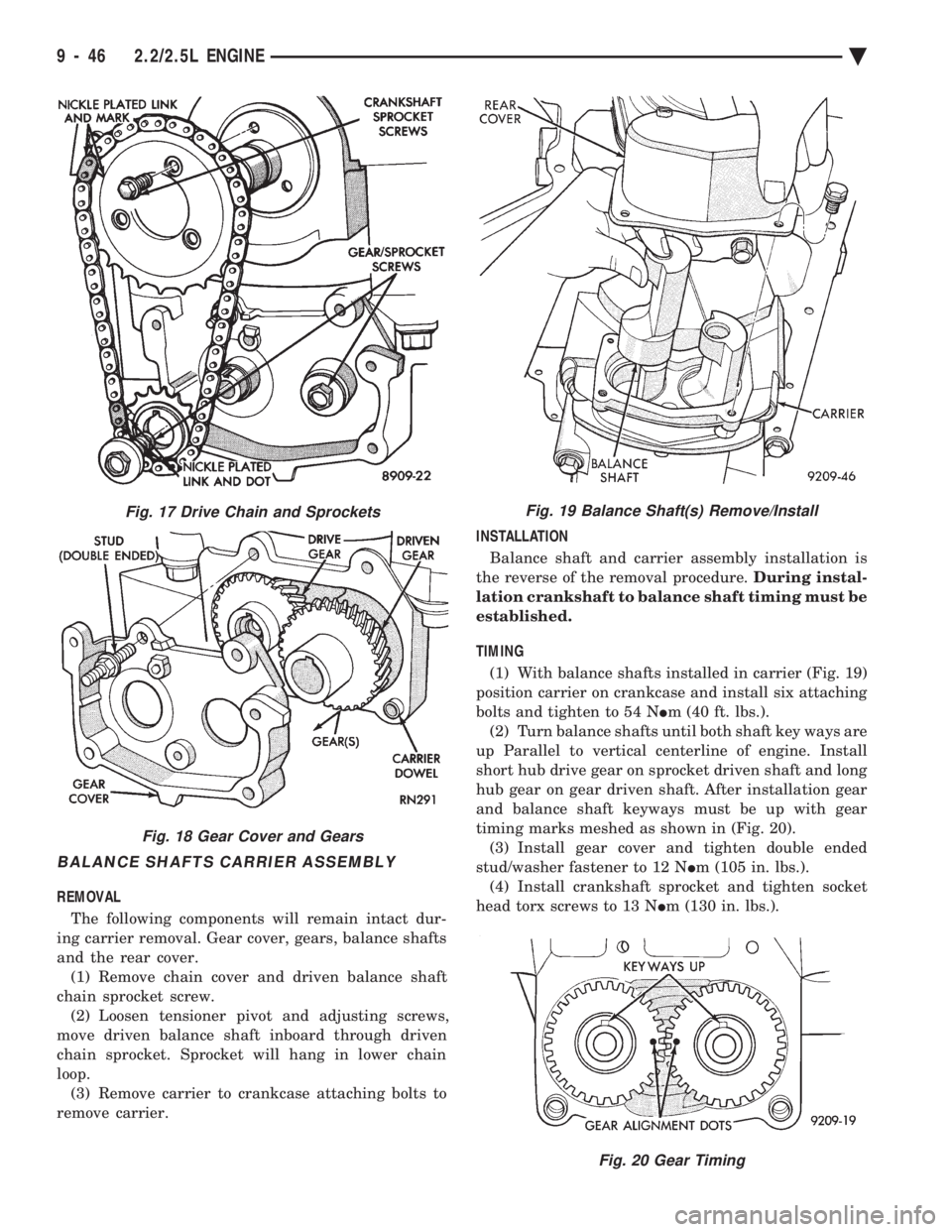
(1) With balance shafts installed in carrier (Fig. 19)
position carrier on crankcase and install six attaching
bolts and tighten to 54 N Im (40 ft. lbs.).
(2) Turn balance shafts until both shaft key ways are
up Parallel to vertical centerline of engine. Install
short hub drive gear on sprocket driven shaft and long
hub gear on gear driven shaft. After installation gear
and balance shaft keyways must be up with gear
timing marks meshed as shown in (Fig. 20). (3) Install gear cover and tighten double ended
stud/washer fastener to 12 N Im (105 in. lbs.).
(4) Install crankshaft sprocket and tighten socket
head torx screws to 13 N Im (130 in. lbs.).
Fig. 20 Gear Timing
Fig. 17 Drive Chain and Sprockets
Fig. 18 Gear Cover and Gears
Fig. 19 Balance Shaft(s) Remove/Install
9 - 46 2.2/2.5L ENGINE Ä
Page 1613 of 2438
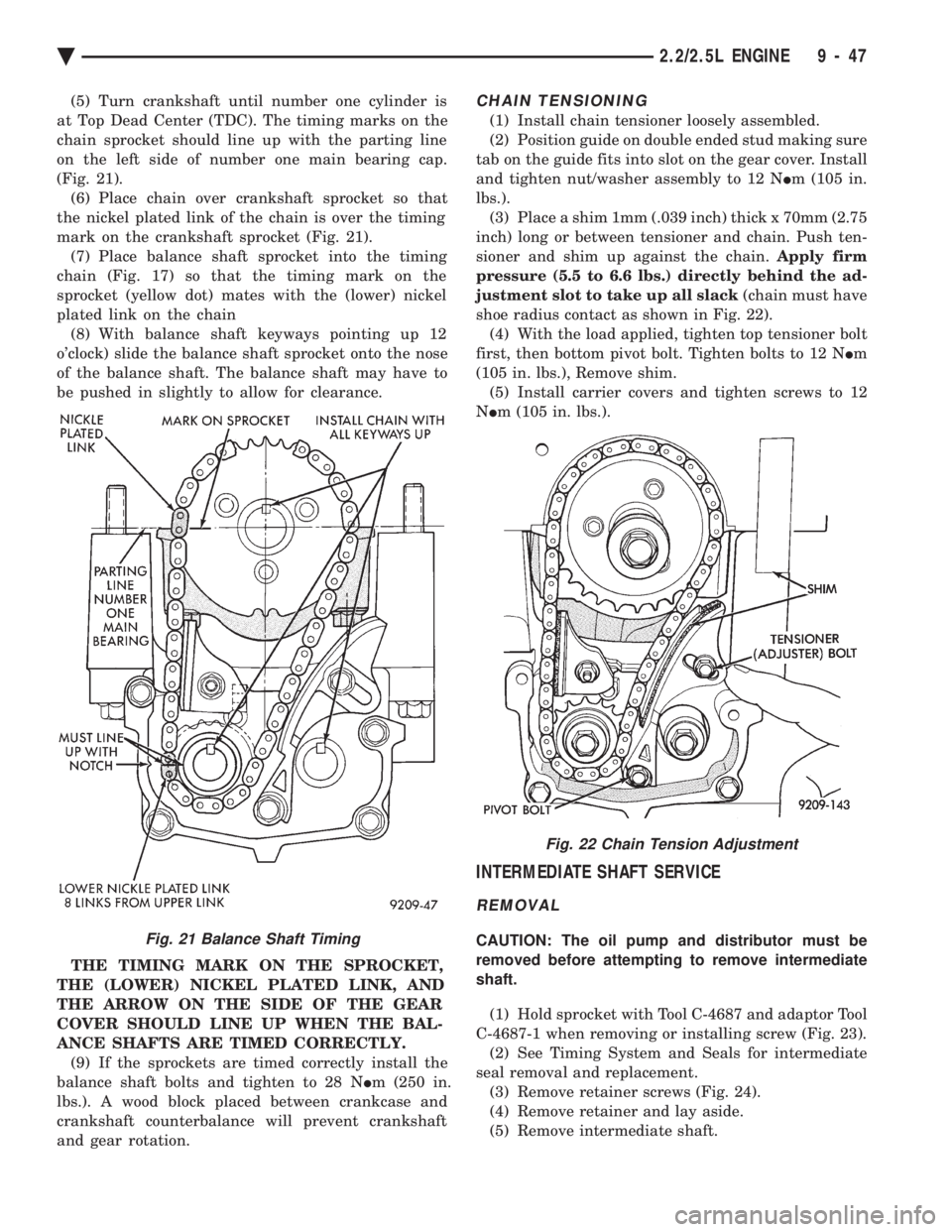
(5) Turn crankshaft until number one cylinder is
at Top Dead Center (TDC). The timing marks on the
chain sprocket should line up with the parting line
on the left side of number one main bearing cap.
(Fig. 21). (6) Place chain over crankshaft sprocket so that
the nickel plated link of the chain is over the timing
mark on the crankshaft sprocket (Fig. 21). (7) Place balance shaft sprocket into the timing
chain (Fig. 17) so that the timing mark on the
sprocket (yellow dot) mates with the (lower) nickel
plated link on the chain (8) With balance shaft keyways pointing up 12
o'clock) slide the balance shaft sprocket onto the nose
of the balance shaft. The balance shaft may have to
be pushed in slightly to allow for clearance.
THE TIMING MARK ON THE SPROCKET,
THE (LOWER) NICKEL PLATED LINK, AND
THE ARROW ON THE SIDE OF THE GEAR
COVER SHOULD LINE UP WHEN THE BAL-
ANCE SHAFTS ARE TIMED CORRECTLY. (9) If the sprockets are timed correctly install the
balance shaft bolts and tighten to 28 N Im (250 in.
lbs.). A wood block placed between crankcase and
crankshaft counterbalance will prevent crankshaft
and gear rotation.CHAIN TENSIONING
(1) Install chain tensioner loosely assembled.
(2) Position guide on double ended stud making sure
tab on the guide fits into slot on the gear cover. Install
and tighten nut/washer assembly to 12 N Im (105 in.
lbs.). (3) Place a shim 1mm (.039 inch) thick x 70mm (2.75
inch) long or between tensioner and chain. Push ten-
sioner and shim up against the chain. Apply firm
pressure (5.5 to 6.6 lbs.) directly behind the ad-
justment slot to take up all slack (chain must have
shoe radius contact as shown in Fig. 22). (4) With the load applied, tighten top tensioner bolt
first, then bottom pivot bolt. Tighten bolts to 12 N Im
(105 in. lbs.), Remove shim. (5) Install carrier covers and tighten screws to 12
N Im (105 in. lbs.).
INTERMEDIATE SHAFT SERVICE
REMOVAL
CAUTION: The oil pump and distributor must be
removed before attempting to remove intermediate
shaft.
(1) Hold sprocket with Tool C-4687 and adaptor Tool
C-4687-1 when removing or installing screw (Fig. 23). (2) See Timing System and Seals for intermediate
seal removal and replacement. (3) Remove retainer screws (Fig. 24).
(4) Remove retainer and lay aside.
(5) Remove intermediate shaft.Fig. 21 Balance Shaft Timing
Fig. 22 Chain Tension Adjustment
Ä 2.2/2.5L ENGINE 9 - 47
Page 1744 of 2438
INSTRUMENT PANEL CLUSTER IDENTIFICATIONÐFLEXIBLE FUEL AA-BODY
Flexible fuel A-Body vehicles use a unique gauge
cluster. To identify the cluster, remove it from the
instrument panel and check the number on the tag
on the top. If the part number matches the number
in the parts book for flexible fuel A-bodies, the vehi-
cle was built with the correct cluster. Refer to Group
8E, Instrument Panel and Gauges, for cluster re-
moval and installation.
METHANOL CONCENTRATION SENSORÐFLEXIBLE
FUEL AA-BODY
The methanol concentration sensor contains a mi-
croprocessor that determines the percentage of gaso-
line and methanol in the fuel system. From the
methanol concentration sensor input, the powertrain
control module (PCM) determines the amount of
methanol in the fuel. The vehicle can operate on a
mixtures up to 85 percent methanol, 15 percent gas-
oline. The methanol concentration sensor output voltages
varies with the percent of methanol in the fuel sys-
tem. The sensor output voltage (input for PCM)
ranges from 0.5 volts for pure gasoline to 4.75 volts
for 85 percent methanol. For two seconds at key ON
when the operator starts the vehicle, the sensor cal-
ibrates the PCM. During the calibration period the
sensor sends 4.45 volts to the PCM as a correction
factor. The methanol concentration sensor has a built-in
shutdown capability. If the sensor shuts down, it de-
faults to the previous learned value (output voltage
based on methanol percentage of fuel). The methanol concentration sensor attaches to a
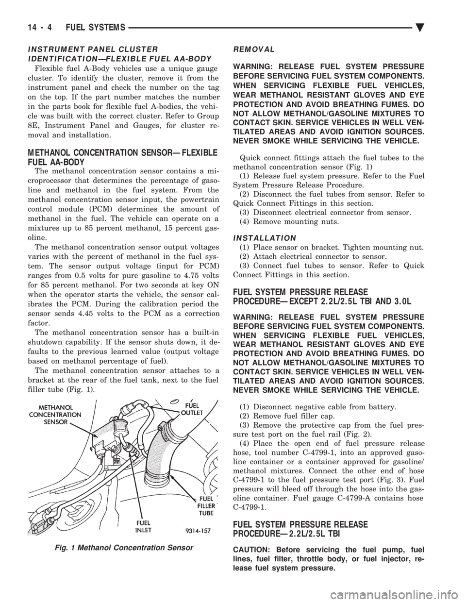
bracket at the rear of the fuel tank, next to the fuel
filler tube (Fig. 1).
REMOVAL
WARNING: RELEASE FUEL SYSTEM PRESSURE
BEFORE SERVICING FUEL SYSTEM COMPONENTS.
WHEN SERVICING FLEXIBLE FUEL VEHICLES,
WEAR METHANOL RESISTANT GLOVES AND EYE
PROTECTION AND AVOID BREATHING FUMES. DO
NOT ALLOW METHANOL/GASOLINE MIXTURES TO
CONTACT SKIN. SERVICE VEHICLES IN WELL VEN-
TILATED AREAS AND AVOID IGNITION SOURCES.
NEVER SMOKE WHILE SERVICING THE VEHICLE.
Quick connect fittings attach the fuel tubes to the
methanol concentration sensor (Fig. 1) (1) Release fuel system pressure. Refer to the Fuel
System Pressure Release Procedure. (2) Disconnect the fuel tubes from sensor. Refer to
Quick Connect Fittings in this section. (3) Disconnect electrical connector from sensor.
(4) Remove mounting nuts.
INSTALLATION
(1) Place sensor on bracket. Tighten mounting nut.
(2) Attach electrical connector to sensor.
(3) Connect fuel tubes to sensor. Refer to Quick
Connect Fittings in this section.
FUEL SYSTEM PRESSURE RELEASE
PROCEDUREÐEXCEPT 2.2L/2.5L TBI AND 3.0L
WARNING: RELEASE FUEL SYSTEM PRESSURE
BEFORE SERVICING FUEL SYSTEM COMPONENTS.
WHEN SERVICING FLEXIBLE FUEL VEHICLES,
WEAR METHANOL RESISTANT GLOVES AND EYE
PROTECTION AND AVOID BREATHING FUMES. DO
NOT ALLOW METHANOL/GASOLINE MIXTURES TO
CONTACT SKIN. SERVICE VEHICLES IN WELL VEN-
TILATED AREAS AND AVOID IGNITION SOURCES.
NEVER SMOKE WHILE SERVICING THE VEHICLE.
(1) Disconnect negative cable from battery.
(2) Remove fuel filler cap.
(3) Remove the protective cap from the fuel pres-
sure test port on the fuel rail (Fig. 2). (4) Place the open end of fuel pressure release
hose, tool number C-4799-1, into an approved gaso-
line container or a container approved for gasoline/
methanol mixtures. Connect the other end of hose
C-4799-1 to the fuel pressure test port (Fig. 3). Fuel
pressure will bleed off through the hose into the gas-
oline container. Fuel gauge C-4799-A contains hose
C-4799-1.
FUEL SYSTEM PRESSURE RELEASE
PROCEDUREÐ2.2L/2.5L TBI
CAUTION: Before servicing the fuel pump, fuel
lines, fuel filter, throttle body, or fuel injector, re-
lease fuel system pressure.Fig. 1 Methanol Concentration Sensor
14 - 4 FUEL SYSTEMS Ä
Page 1746 of 2438
FUEL SYSTEM PRESSURE
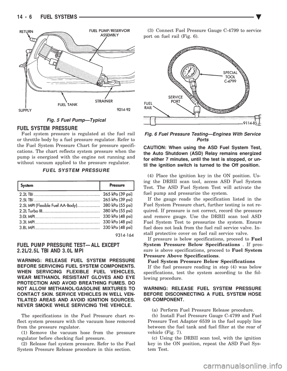
Fuel system pressure is regulated at the fuel rail
or throttle body by a fuel pressure regulator. Refer to
the Fuel System Pressure Chart for pressure specifi-
cations. The chart reflects system pressure when the
pump is energized with the engine not running and
without vacuum applied to the pressure regulator.
FUEL PUMP PRESSURE TESTÐALL EXCEPT
2.2L/2.5L TBI AND 3.0L MPI
WARNING: RELEASE FUEL SYSTEM PRESSURE
BEFORE SERVICING FUEL SYSTEM COMPONENTS.
WHEN SERVICING FLEXIBLE FUEL VEHICLES,
WEAR METHANOL RESISTANT GLOVES AND EYE
PROTECTION AND AVOID BREATHING FUMES. DO
NOT ALLOW METHANOL/GASOLINE MIXTURES TO
CONTACT SKIN. SERVICE VEHICLES IN WELL VEN-
TILATED AREAS AND AVOID IGNITION SOURCES.
NEVER SMOKE WHILE SERVICING THE VEHICLE.
The specifications in the Fuel Pressure chart re-
flect system pressure with the vacuum hose removed
from the pressure regulator. (1) Remove the vacuum hose from the pressure
regulator before checking fuel pressure. (2) Release fuel system pressure. Refer to the Fuel
System Pressure Release procedure in this section. (3) Connect Fuel Pressure Gauge C-4799 to service
port on fuel rail (Fig. 6).
CAUTION: When using the ASD Fuel System Test,
the Auto Shutdown (ASD) Relay remains energized
for either 7 minutes, until the test is stopped, or un-
til the ignition switch is turned to the Off position.
(4) Place the ignition key in the ON position. Us-
ing the DRBII scan tool, access ASD Fuel System
Test. The ASD Fuel System Test will activate the
fuel pump and pressurize the system. If the gauge reads the specification listed in the
Fuel System Pressure chart, further testing is not re-
quired. If pressure is not correct, record the pressure
and remove gauge. Use the DRBII scan tool ASD
Fuel System Test to pressurize the system. Ensure
fuel does not leak from the fuel rail service valve. In-
stall protective cover on fuel rail service valve. If pressure is below specifications, proceed to Fuel
System Pressure Below Specifications . If pres-
sure is above specifications, proceed to Fuel System
Pressure Above Specifications .
Fuel System Pressure Below Specifications
If the fuel pressure reading in step (4) was below
specifications, test the system according to the fol-
lowing procedure.
WARNING: RELEASE FUEL SYSTEM PRESSURE
BEFORE DISCONNECTING A FUEL SYSTEM HOSE
OR COMPONENT.
(a) Perform Fuel Pressure Release procedure.
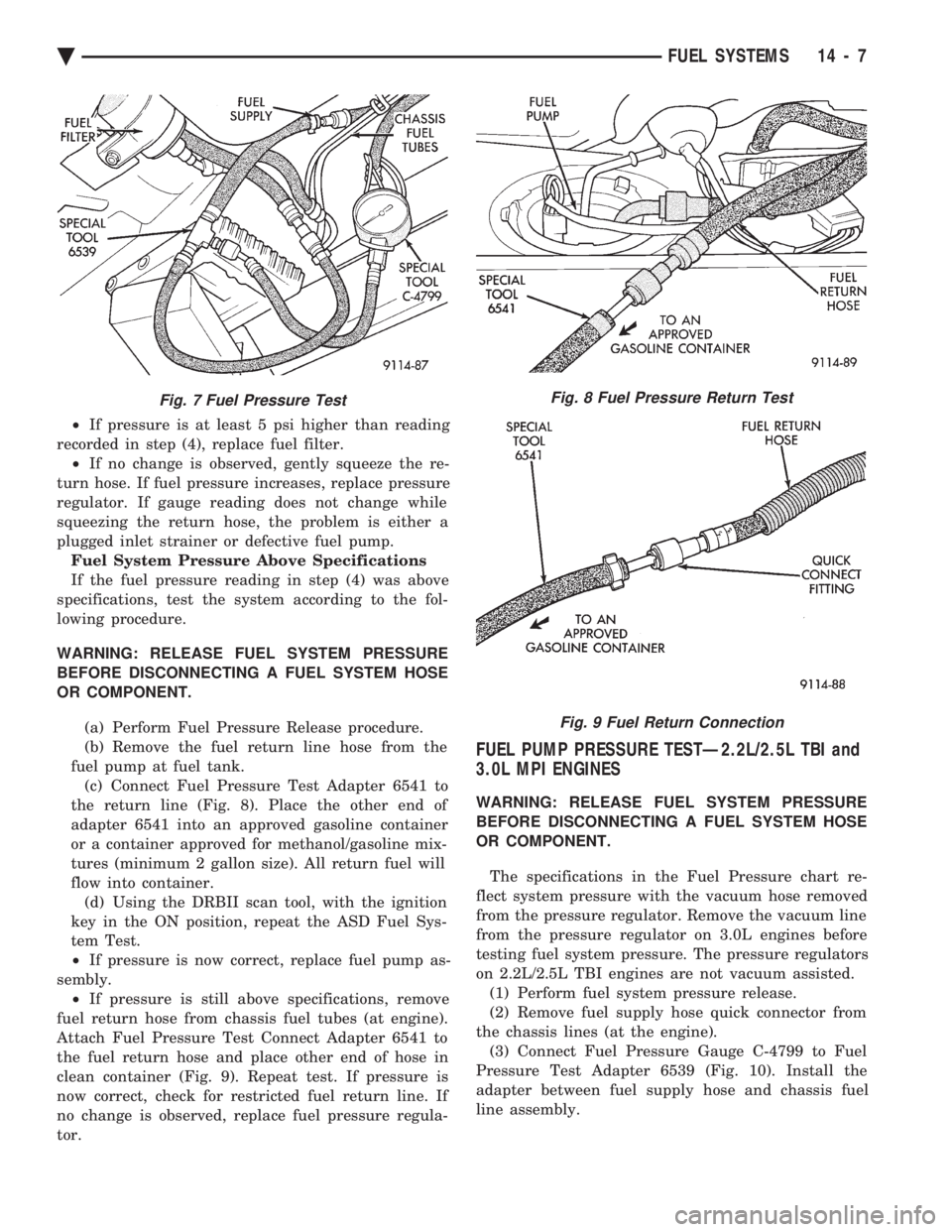
(b) Install Fuel Pressure Gauge C-4799 and Fuel
Pressure Test Adapter 6539 in the fuel supply line
between the fuel tank and fuel filter at the rear of
vehicle (Fig. 7). (c) Using the DRBII scan tool, with the ignition
key in the ON position, repeat the ASD Fuel Sys-
tem Test.
Fig. 5 Fuel PumpÐTypical
FUEL SYSTEM PRESSURE
Fig. 6 Fuel Pressure TestingÐEngines With Service Ports
14 - 6 FUEL SYSTEMS Ä
Page 1747 of 2438
² If pressure is at least 5 psi higher than reading
recorded in step (4), replace fuel filter. ² If no change is observed, gently squeeze the re-
turn hose. If fuel pressure increases, replace pressure
regulator. If gauge reading does not change while
squeezing the return hose, the problem is either a
plugged inlet strainer or defective fuel pump. Fuel System Pressure Above Specifications
If the fuel pressure reading in step (4) was above
specifications, test the system according to the fol-
lowing procedure.
WARNING: RELEASE FUEL SYSTEM PRESSURE
BEFORE DISCONNECTING A FUEL SYSTEM HOSE
OR COMPONENT.
(a) Perform Fuel Pressure Release procedure.
(b) Remove the fuel return line hose from the
fuel pump at fuel tank. (c) Connect Fuel Pressure Test Adapter 6541 to
the return line (Fig. 8). Place the other end of
adapter 6541 into an approved gasoline container
or a container approved for methanol/gasoline mix-
tures (minimum 2 gallon size). All return fuel will
flow into container. (d) Using the DRBII scan tool, with the ignition
key in the ON position, repeat the ASD Fuel Sys-
tem Test.
² If pressure is now correct, replace fuel pump as-
sembly. ² If pressure is still above specifications, remove
fuel return hose from chassis fuel tubes (at engine).
Attach Fuel Pressure Test Connect Adapter 6541 to
the fuel return hose and place other end of hose in
clean container (Fig. 9). Repeat test. If pressure is
now correct, check for restricted fuel return line. If
no change is observed, replace fuel pressure regula-
tor.
FUEL PUMP PRESSURE TESTÐ2.2L/2.5L TBI and
3.0L MPI ENGINES
WARNING: RELEASE FUEL SYSTEM PRESSURE
BEFORE DISCONNECTING A FUEL SYSTEM HOSE
OR COMPONENT.
The specifications in the Fuel Pressure chart re-
flect system pressure with the vacuum hose removed
from the pressure regulator. Remove the vacuum line
from the pressure regulator on 3.0L engines before
testing fuel system pressure. The pressure regulators
on 2.2L/2.5L TBI engines are not vacuum assisted. (1) Perform fuel system pressure release.
(2) Remove fuel supply hose quick connector from
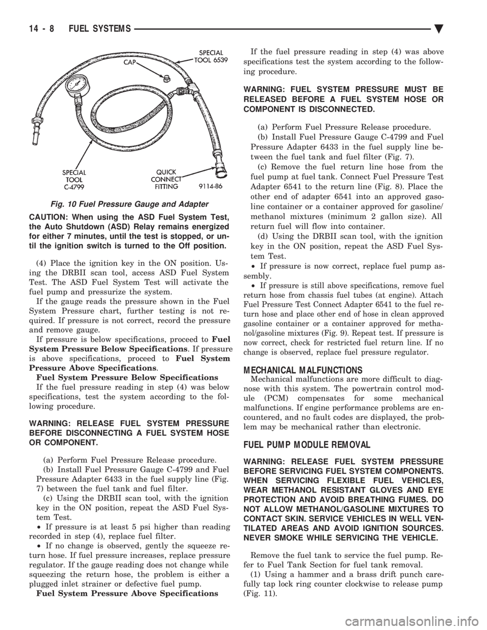
the chassis lines (at the engine). (3) Connect Fuel Pressure Gauge C-4799 to Fuel
Pressure Test Adapter 6539 (Fig. 10). Install the
adapter between fuel supply hose and chassis fuel
line assembly.
Fig. 7 Fuel Pressure TestFig. 8 Fuel Pressure Return Test
Fig. 9 Fuel Return Connection
Ä FUEL SYSTEMS 14 - 7
Page 1748 of 2438
CAUTION: When using the ASD Fuel System Test,
the Auto Shutdown (ASD) Relay remains energized
for either 7 minutes, until the test is stopped, or un-
til the ignition switch is turned to the Off position.
(4) Place the ignition key in the ON position. Us-
ing the DRBII scan tool, access ASD Fuel System
Test. The ASD Fuel System Test will activate the
fuel pump and pressurize the system. If the gauge reads the pressure shown in the Fuel
System Pressure chart, further testing is not re-
quired. If pressure is not correct, record the pressure
and remove gauge. If pressure is below specifications, proceed to Fuel
System Pressure Below Specifications . If pressure
is above specifications, proceed to Fuel System
Pressure Above Specifications .
Fuel System Pressure Below Specifications
If the fuel pressure reading in step (4) was below
specifications, test the system according to the fol-
lowing procedure.
WARNING: RELEASE FUEL SYSTEM PRESSURE
BEFORE DISCONNECTING A FUEL SYSTEM HOSE
OR COMPONENT.
(a) Perform Fuel Pressure Release procedure.
(b) Install Fuel Pressure Gauge C-4799 and Fuel
Pressure Adapter 6433 in the fuel supply line (Fig.
7) between the fuel tank and fuel filter. (c) Using the DRBII scan tool, with the ignition
key in the ON position, repeat the ASD Fuel Sys-
tem Test.
² If pressure is at least 5 psi higher than reading
recorded in step (4), replace fuel filter. ² If no change is observed, gently the squeeze re-
turn hose. If fuel pressure increases, replace pressure
regulator. If the gauge reading does not change while
squeezing the return hose, the problem is either a
plugged inlet strainer or defective fuel pump. Fuel System Pressure Above Specifications If the fuel pressure reading in step (4) was above
specifications test the system according to the follow-
ing procedure.
WARNING: FUEL SYSTEM PRESSURE MUST BE
RELEASED BEFORE A FUEL SYSTEM HOSE OR
COMPONENT IS DISCONNECTED.
(a) Perform Fuel Pressure Release procedure.
(b) Install Fuel Pressure Gauge C-4799 and Fuel
Pressure Adapter 6433 in the fuel supply line be-
tween the fuel tank and fuel filter (Fig. 7). (c) Remove the fuel return line hose from the
fuel pump at fuel tank. Connect Fuel Pressure Test
Adapter 6541 to the return line (Fig. 8). Place the
other end of adapter 6541 into an approved gaso-
line container or a container approved for gasoline/
methanol mixtures (minimum 2 gallon size). All
return fuel will flow into container. (d) Using the DRBII scan tool, with the ignition
key in the ON position, repeat the ASD Fuel Sys-
tem Test.
² If pressure is now correct, replace fuel pump as-
sembly. ²
If pressure is still above specifications, remove fuel
return hose from chassis fuel tubes (at engine). Attach
Fuel Pressure Test Connect Adapter 6541 to the fuel re-
turn hose and place other end of hose in clean approved
gasoline container or a container approved for metha-
nol/gasoline mixtures (Fig. 9). Repeat test. If pressure is
now correct, check for restricted fuel return line. If no
change is observed, replace fuel pressure regulator.
MECHANICAL MALFUNCTIONS
Mechanical malfunctions are more difficult to diag-
nose with this system. The powertrain control mod-
ule (PCM) compensates for some mechanical
malfunctions. If engine performance problems are en-
countered, and no fault codes are displayed, the prob-
lem may be mechanical rather than electronic.
FUEL PUMP MODULE REMOVAL
WARNING: RELEASE FUEL SYSTEM PRESSURE
BEFORE SERVICING FUEL SYSTEM COMPONENTS.
WHEN SERVICING FLEXIBLE FUEL VEHICLES,
WEAR METHANOL RESISTANT GLOVES AND EYE
PROTECTION AND AVOID BREATHING FUMES. DO
NOT ALLOW METHANOL/GASOLINE MIXTURES TO
CONTACT SKIN. SERVICE VEHICLES IN WELL VEN-
TILATED AREAS AND AVOID IGNITION SOURCES.
NEVER SMOKE WHILE SERVICING THE VEHICLE.
Remove the fuel tank to service the fuel pump. Re-
fer to Fuel Tank Section for fuel tank removal. (1) Using a hammer and a brass drift punch care-
fully tap lock ring counter clockwise to release pump
(Fig. 11).
Fig. 10 Fuel Pressure Gauge and Adapter
14 - 8 FUEL SYSTEMS Ä