1993 CHEVROLET PLYMOUTH ACCLAIM display
[x] Cancel search: displayPage 1903 of 2438
line. However, these could result in a rich or lean
condition causing an oxygen sensor fault to be stored in
the PCM. Secondary Ignition Circuit - The PCM cannot
detect an inoperative ignition coil, fouled or worn spark
plugs, ignition cross firing, or open spark plug cables. Engine Timing - The PCM cannot detect an incor-
rectly indexed timing chain, camshaft sprocket and
crankshaft sprocket. However, these could result in a
rich or lean condition causing an oxygen sensor fault to
be stored in the PCM. Cylinder Compression - The PCM cannot detect
uneven, low, or high engine cylinder compression. Exhaust System - The PCM cannot detect a
plugged, restricted or leaking exhaust system. Fuel Injector Malfunctions - The PCM cannot
determine if a fuel injector is clogged, the needle is
sticking or the wrong injector is installed. However,
these could result in a rich or lean condition causing an
oxygen sensor fault to be stored in the PCM. Excessive Oil Consumption - Although the PCM
monitors exhaust stream oxygen content when the
system is in closed loop, it cannot determine excessive
oil consumption. Throttle Body Air Flow - The PCM cannot detect a
clogged or restricted air cleaner inlet or filter element. Evaporative System - The PCM will not detect a
restricted, plugged or loaded evaporative purge canis-
ter. Vacuum Assist - Leaks or restrictions in the
vacuum circuits of vacuum assisted engine control
system devices are not monitored by the PCM. How-
ever, these could result in a MAP sensor fault being
stored in the PCM. PCM System Ground - The PCM cannot determine
a poor system ground. However, a diagnostic trouble
code may be generated as a result of this condition. PCM Connector Engagement - The PCM cannot
determine spread or damaged connector pins. How-
ever, a diagnostic trouble code may be generated as a
result of this condition.
HIGH AND LOW LIMITS
The powertrain control module (PCM) compares in-
put signal voltages from each input device with estab-
lished high and low limits for the device. If the input
voltage is not within limits and other diagnostic
trouble code criteria are met, a diagnostic trouble code
will be stored in memory. Other diagnostic trouble code
criteria might include engine RPM limits or input
voltages from other sensors or switches that must be
present before a fault condition can be verified.
DIAGNOSTIC TROUBLE CODE DESCRIPTION
A diagnostic trouble code indicates that the power-
train control module (PCM) has recognized an abnor- mal condition in the system. Diagnostic trouble codes
can be obtained from the malfunction indicator lamp
(Check Engine lamp on the instrument panel) or from
the DRBII scan tool. Diagnostic trouble codes indicate
the results of a failure but do not identify the failed
component directly.
SYSTEM TESTS
WARNING: APPLY PARKING BRAKE AND/OR BLOCK
WHEELS BEFORE PERFORMING ANY TEST ON AN
OPERATING ENGINE.
OBTAINING DIAGNOSTIC TROUBLE CODES
(1) Connect the DRBII scan tool to the data link
connector located in the engine compartment near the
driver side strut tower (Fig. 1). (2) Start the engine if possible, cycle the transaxle
selector and the A/Cswitch if applicable. Shut off the
engine. (3) Turn the ignition switch on, access Read Fault
Screen. Record all the fault messages shown on the
DRBII scan tool. Observe the malfunction indicator
lamp (check engine lamp on the instrument panel). The
lamp should light for 2 seconds then go out (bulb
check). Diagnostic trouble code erasure; access erase
diagnostic trouble code data
STATE DISPLAY TEST MODE
The switch inputs used by the powertrain control
module (PCM) have only two recognized states, HIGH
and LOW. For this reason, the PCM cannot recognize
the difference between a selected switch position ver-
sus an open circuit, a short circuit, or a defective
switch. If the change is displayed, it can be assumed
that the entire switch circuit to the PCM is functional.
From the state display screen access either State
Display Inputs and Outputs or State Display Sensors.
STATE DISPLAY INPUTS AND OUTPUTS
Connect the DRBII scan tool to the vehicle and access
the State Display screen. Then access Inputs and
Outputs. The following is a list of the engine control
system functions accessible through the Inputs and
Outputs screen. Park/Neutral Switch
Speed Control Resume
Brake Switch
Speed Control On/Off
Speed Control Set
A/C Switch Sense
S/C Vent Solenoid
Ä FUEL SYSTEMS 14 - 163
Page 1906 of 2438
S/C Vacuum Solenoid
A/C Clutch Relay
EGR Solenoid
Auto Shutdown Relay
Radiator Fan Relay
Purge Solenoid
Malfunction Indicator Lamp (Check Engine Lamp)
STATE DISPLAY SENSORS
Connect the DRBII scan tool to the vehicle and ac-
cess the State Display screen. Then access Sensor
Display. The following is a list of the engine control
system functions accessible through the Sensor Dis-
play screen. Oxygen Sensor Signal
Engine Coolant Temperature
Engine Coolant Temp Sensor
Throttle Position
Minimum Throttle
Battery Voltage
MAP Sensor Reading
Idle Air Control Motor Position
Adaptive Fuel Factor
Barometric Pressure
Min Airflow Idle Spd (speed)
Engine Speed
DIS Sensor Status
Fault #1 Key-On Info
Module Spark Advance
Speed Control Target
Fault #2 Key-on Info
Fault #3 Key-on Info
Speed Control Status
Speed Control Switch Voltage
Charging System Goal
Theft Alarm Status
Map Sensor Voltage
Vehicle Speed
Oxygen Sensor State
MAP Gauge Reading
Throttle Opening (percentage)
Total Spark Advance
CIRCUIT ACTUATION TEST MODE
The circuit actuation test mode checks for proper
operation of output circuits or devices which the pow-
ertrain control module (PCM) cannot internally rec-
ognize. The PCM can attempt to activate these
outputs and allow an observer to verify proper oper-
ation. Most of the tests provide an audible or visual
indication of device operation (click of relay contacts,
spray fuel, etc.). Except for intermittent conditions, if
a device functions properly during testing, assume
the device, its associated wiring, and driver circuit
working correctly.
OBTAINING CIRCUIT ACTUATION TEST
Connect the DRBII scan tool to the vehicle and ac-
cess the Actuators screen. The following is a list of
the engine control system functions accessible
through Actuators screens. Stop All Tests
Ignition Coil #1
Ignition Coil #2
Ignition Coil #3
Fuel Injector #1
Fuel Injector #2
Fuel Injector #3
Fuel Injector #4
Fuel Injector #5
Fuel Injector #6
Idle Air Control Motor Open/Close
Radiator Fan Relay
A/C Clutch Relay
Auto Shutdown Relay
EVAP Purge Solenoid
S/C Servo Solenoids
Generator Field
EGR Solenoid
All Solenoids/Relays
ASD Fuel System Test
Speed Control Vacuum Solenoid
Speed Control Vent Solenoid
THROTTLE BODY MINIMUM AIR FLOW CHECK
PROCEDURE
(1) Warm engine in Park or Neutral until the cool-
ing fan has cycled on and off at least once. (2) Ensure that all accessories are off.
(3) Shut off engine.
(4) Disconnect the PCV valve hose from the intake
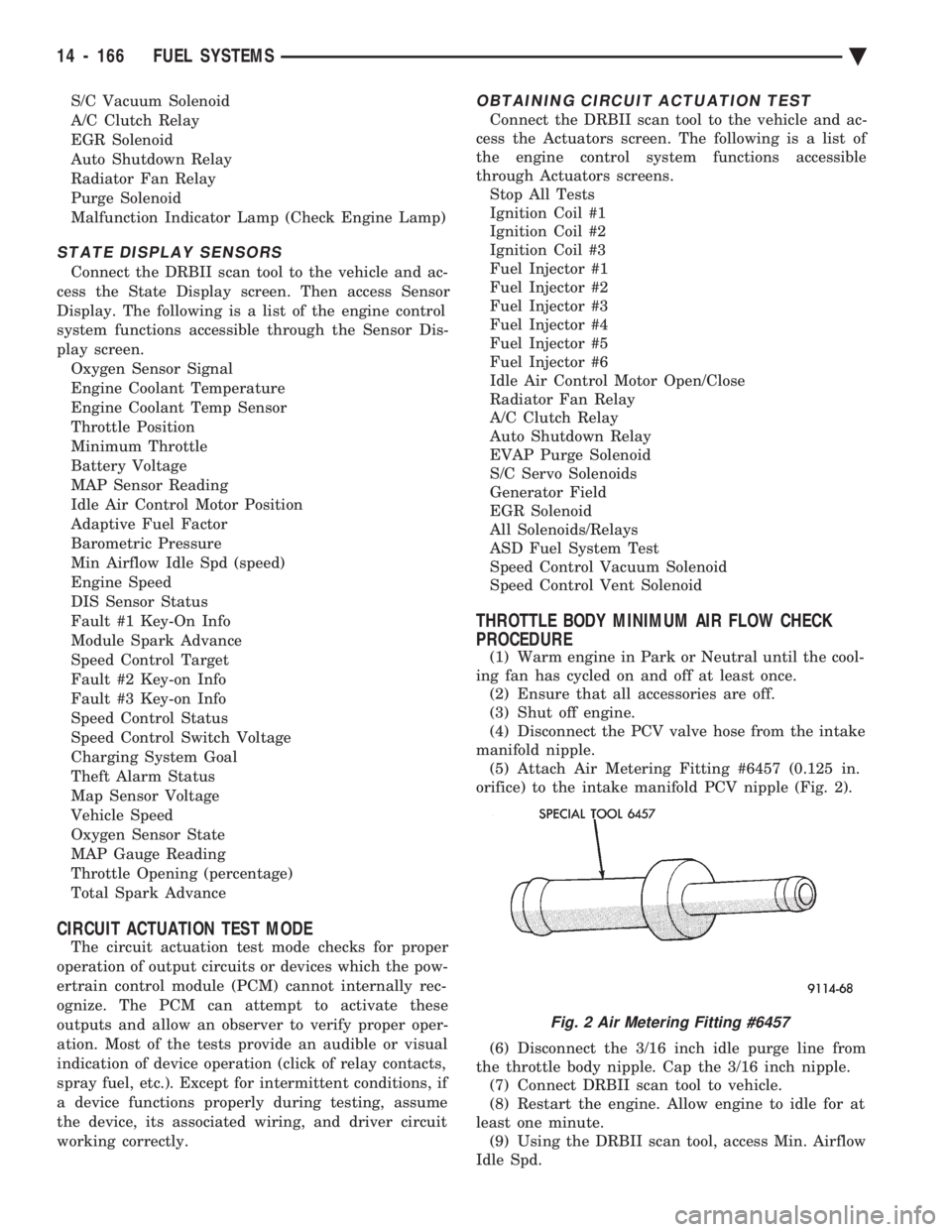
manifold nipple. (5) Attach Air Metering Fitting #6457 (0.125 in.
orifice) to the intake manifold PCV nipple (Fig. 2).
(6) Disconnect the 3/16 inch idle purge line from
the throttle body nipple. Cap the 3/16 inch nipple. (7) Connect DRBII scan tool to vehicle.
(8) Restart the engine. Allow engine to idle for at
least one minute. (9) Using the DRBII scan tool, access Min. Airflow
Idle Spd.
Fig. 2 Air Metering Fitting #6457
14 - 166 FUEL SYSTEMS Ä
Page 1907 of 2438
(10) The following will then occur:
² Idle air control motor will fully close.
² Idle spark advance will become fixed.
² Engine RPM will be displayed on DRBII scan tool.
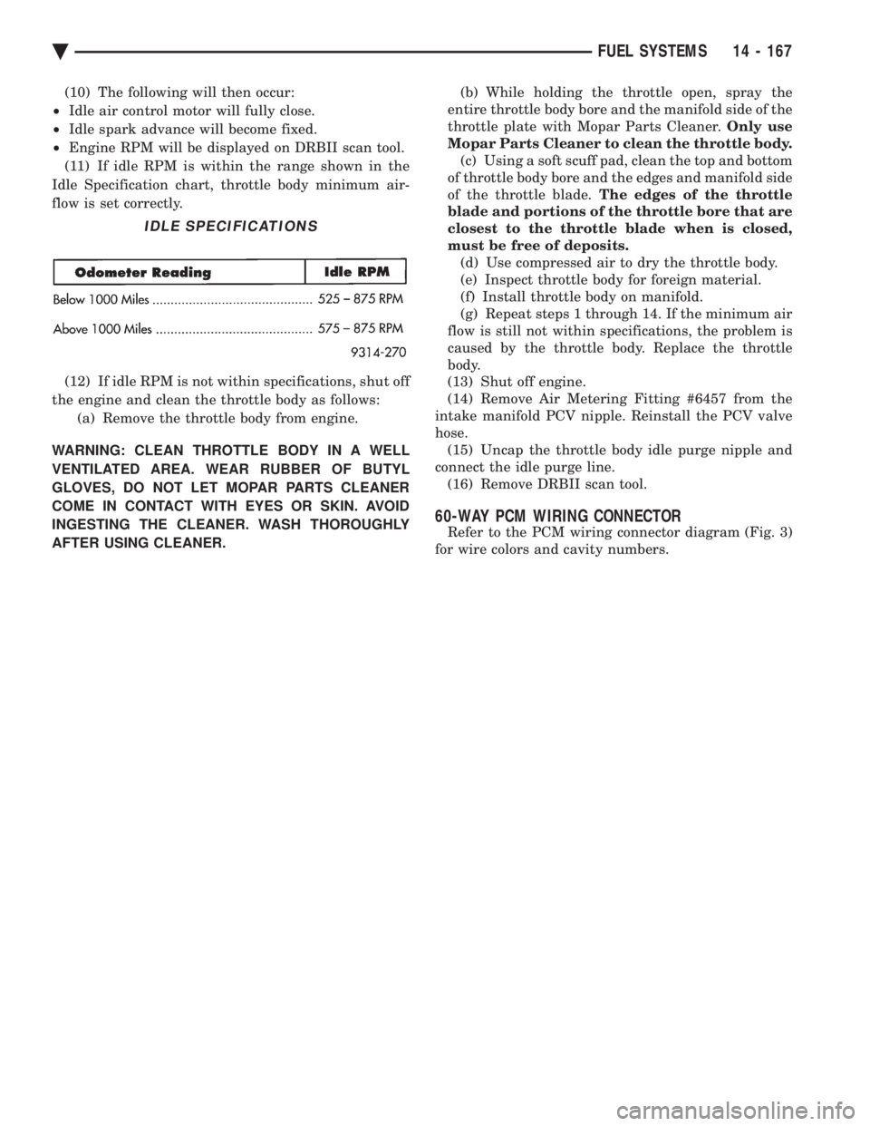
(11) If idle RPM is within the range shown in the
Idle Specification chart, throttle body minimum air-
flow is set correctly.
(12) If idle RPM is not within specifications, shut off
the engine and clean the throttle body as follows: (a) Remove the throttle body from engine.
WARNING: CLEAN THROTTLE BODY IN A WELL
VENTILATED AREA. WEAR RUBBER OF BUTYL
GLOVES, DO NOT LET MOPAR PARTS CLEANER
COME IN CONTACT WITH EYES OR SKIN. AVOID
INGESTING THE CLEANER. WASH THOROUGHLY
AFTER USING CLEANER. (b) While holding the throttle open, spray the
entire throttle body bore and the manifold side of the
throttle plate with Mopar Parts Cleaner. Only use
Mopar Parts Cleaner to clean the throttle body. (c) Using a soft scuff pad, clean the top and bottom
of throttle body bore and the edges and manifold side
of the throttle blade. The edges of the throttle
blade and portions of the throttle bore that are
closest to the throttle blade when is closed,
must be free of deposits. (d) Use compressed air to dry the throttle body.
(e) Inspect throttle body for foreign material.
(f) Install throttle body on manifold.
(g) Repeat steps 1 through 14. If the minimum air
flow is still not within specifications, the problem is
caused by the throttle body. Replace the throttle
body.
(13) Shut off engine.
(14) Remove Air Metering Fitting #6457 from the
intake manifold PCV nipple. Reinstall the PCV valve
hose. (15) Uncap the throttle body idle purge nipple and
connect the idle purge line. (16) Remove DRBII scan tool.
60-WAY PCM WIRING CONNECTOR
Refer to the PCM wiring connector diagram (Fig. 3)
for wire colors and cavity numbers.
IDLE SPECIFICATIONS
Ä FUEL SYSTEMS 14 - 167
Page 2064 of 2438
(7) Press the number 5 on the DRB II scan tool
key pad (Adjustments). (8) Press the number 3 on the DRB II scan tool
key pad (Quick Learn). Then follow the instructions
on the DRB II scan tool screen.
PINION FACTOR PROCEDURE
The vehicle speed readings for the speedometer are
taken from the output speed sensor. Because of dif-
ferent tire sizes and final drive ratios, the transmis-
sion control module must be calibrated to reflect the
different combinations of equipment. A procedure has
been developed called Pinion Factor. It allows the
technician to set the transmission control module ini-
tial setting so that the speedometer readings will be
correct. Failure to perform this procedure will cause a ``No
Speedometer Operation'' condition. This procedure must be performed if the transmis-
sion control module has been replaced. To properly read or reset the Pinion Factor, it is
necessary to use a DRB II scan tool. Perform the fol-
lowing steps with the DRB II scan tool to read or re-
set the Pinion Factor: (1) Plug the DRB II scan tool into the blue CCD
Bus connector. The connector is located under the in-
strument panel on the drivers side of the vehicle. (2) Insert the 1993 DRB II scan tool cartridge into
the DRB II scan tool. (3) The red and green lights on the DRB II scan
tool will light up and then begin flashing. Wait until
the lights stop flashing before continuing with this
procedure. (4) Press the number 4 key (Select System) on the
DRB II scan tool key pad. Item number 4 will not ap-
pear on the DRB II scan tool screen unless you scroll
down. It is not necessary to scroll down to be able to
choose item 4. (5) Press the number 2 on the DRB II scan tool
key pad (Transmission). (6) Press the number 1 on the DRB II scan tool
key pad. Wait for the DRB II scan tool to perform the
following three tests before continuing (These tests
are done automatically by the DRB II scan tool).
² Bus Test
² Initialize
² Transmission Control Module Part Number
(7) Press the number 5 on the DRB II scan tool
key pad (Adjustments). (8) Press the number 2 on the DRB II scan tool
key pad (Pinion Factor). Then follow the instructions
on the DRB II scan tool screen.
TORQUE CONVERTER CLUTCH BREAK-IN
PROCEDURE
A torque converter clutch break-in program is be-
ing used on all models with a 41TE. This program
will properly condition the torque converter clutch. This will eliminate shudder during partial torque
converter clutch operation on a new torque converter.
If the torque converter is replaced, the new clutch
within the torque converter will require break-in.
The current break-in status stored in the transmis-
sion control module will have to be reset to the start
of break-in with the DRB II scan tool. If a new transmission control module is put on the
vehicle, the status will be at the start of break-in.
This status is acceptable regardless of the mileage on
the torque converter. No modification of the break-in
status is required. To properly service these vehicles, it is necessary to
use a DRB II scan tool to read or reset the break-in
status. Perform the following steps with the DRB II
scan tool to reset the break-in status: (1) Plug the DRB II scan tool into the blue CCD
Bus connector. The connector is located under the in-
strument panel on the drivers side of the vehicle. (2) Insert the 1993 DRB II scan tool cartridge into
the DRB II scan tool. (3) The red and green lights on the DRB II scan
tool will light up and then begin flashing. Wait until
the lights stop flashing before continuing with this
procedure. (4) Press the number 4 key (Select System) on the
DRB II scan tool key pad. Item number 4 will not ap-
pear on the DRB II scan tool screen unless you scroll
down. It is not necessary to scroll down to be able to
choose item 4. (5) Press the number 2 on the DRB II scan tool
key pad (Transmission). (6) Press the number 1 on the DRB II scan tool
key pad. Wait for the DRB II scan tool to perform the
following three tests before continuing (These tests
are done automatically by the DRB II scan tool).
² Bus Test
² Initialize
² Transmission Control Module Part Number
(7) Press the number 5 on the DRB II scan tool
key pad (Adjustments). (8) Press the number 1 on the DRB II scan tool
key pad (Reset LU Clutch). The DRB II scan tool will
display one of three screens. (a) LU Clutch Break-in Status: Start
(b) LU Clutch Break-in Status: In-progress
Press ENTER to Reset Break-in status (c) LU Clutch Break-in Status: CompletePress
ENTER to Reset Break-in status
If screen (a) appears, the transmission control mod-
ule is at the beginning of its break-in program. No
further action is required. If screen (b) appears, the transmission control mod-
ule is in the middle of a its break-in program. Press
the enter key on the DRB II scan tool key pad to re-
turn the status to the start of break-in.
21 - 104 TRANSAXLE Ä
Page 2105 of 2438
41TE ON-BOARD DIAGNOSTICS INDEX
page page
CCD Bus .............................. 145
Diagnostic Trouble Code Charts ............ 146
Diagnostic Trouble Codes ................. 145
DRB II Scan Tool ....................... 146 General Information
...................... 145
Limp-In Mode .......................... 145
On-Board Diagnostics Information ........... 145
GENERAL INFORMATION
The information in this manual is designed to help
the technician understand and repair the transaxle
with the aid of the built in on-board diagnostics. Chrysler Corporation has developed a com-
plete set of diagnostic manuals which cover the
diagnosis of the 41TE transaxle. They have been
designed to make transaxle diagnosis accurate
and simple. Use these manuals with the DRB II
scan tool and the latest cartridge, when diagnos-
ing transaxle problems.
ON-BOARD DIAGNOSTICS INFORMATION
The 41TE transaxle is controlled and monitored by
the transmission control module. The transmission
control module monitors critical input and output
circuits within the transaxle. Some circuits are tested continuously; others are
checked only under certain conditions. Each circuit
monitored by the transmission control module has a
corresponding fault message assigned to it that can be
read with the DRB II scan tool. If the on-board diagnostic system senses that one of
the circuits is malfunctioning, the corresponding code
is stored in memory. If the malfunction goes away after
the code is stored, the transmission control module will
erase the code after 75 key cycles.
CCD BUS
In order to diagnose the 41TE transaxle, diagnostic
trouble codes in the transmission control module's
memory should be read. Use the Diagnostic Readout
Box (DRB II) scan tool to read codes. If more than one
diagnostic trouble code exists, diagnostic priority
should be given to the most recent code. With CCD bus
bias and communication problems, the DRB II scan
tool displays an appropriate message. Diagnostic
trouble codes might not be accessible until the bus
problem is fixed. The following is a list of probable
causes for a bus problem:
² Open or short to ground/battery in either or both
CCD bus wires (pins 4 and 43).
² Open or short to ground/battery in either or both
41TE transaxle's bias wires (pin 5 and 44) on vehicles
requiring the transaxle to bias the bus.
² Open or short to ground/battery in the diagnostic
connector bus wire. ²
Internal failure of any module connected to the bus.
The CCD bus should have 2.5 volts (+2.5 volts on
CCD+ and -2.5 volts on CCD-). The bus error message displayed by the DRB II scan
tool should be helpful in diagnosing the CCD bus. For more information on diagnosing CCD bus prob-
lems, refer to the 1993 Diagnostic Procedures Manual
(non-communication with the CCD bus). All other
problems refer to the 1993 Body Vehicle Communica-
tions Diagnostic Procedures Manual.
DIAGNOSTIC TROUBLE CODES
Diagnostic Trouble Codes are two-digit numbers that
identify which circuit is malfunctioning. A code can be
set for hydraulic and mechanical reasons as well as for
electrical problems. In most cases, codes do not pin-
point which specific component is defective. Diagnostic trouble codes can only be read with
the use of the DRB II scan tool or equivalent.
HARD FAULTS
Any Diagnostic trouble code that comes back within
3 engine starts (reset count 3 or less) is a ``Hard Fault''.
This means that the defect is there every time the
transmission control module checks that circuit.
SOFT FAULTS
A ``Soft Fault'' is one that occurs intermittently. It is
not there every time the transmission control module
checks the circuit. Most soft faults are caused by wiring
or connector problems. Intermittent defects must be
looked for under the specific conditions that caused
them.
LIMP-IN MODE
The transmission control module continuously
checks for electrical and internal transaxle problems.
When a problem is sensed, the transmission control
module stores a diagnostic trouble code. All but twelve
of these codes cause the transaxle to go into the
``Limp-in mode''. While in this mode, electrical power is
taken away from the transaxle. When this happens,
the only transaxle ranges that will function are:
Ä TRANSAXLE 21 - 145
Page 2370 of 2438
AUTOMATIC TEMPERATURE CONTROL (ATC) INDEX
page page
Ambient Temperature Sensor ............... 67
ATC Computer/Control Panel ................ 66
Blend-Air Door Actuator .................... 69
Computer Aided Diagnostic Tests ............ 72
Diagnostic Trouble Code Definitions .......... 73
Diagnostic Trouble Code Service Procedures . . . 74
Erasing Diagnostic Trouble Codes ............ 83
Fresh/Recirc Door Actuator ................. 68 General InformationÐComponent Operation
.... 66
In-Car Temperature Sensor/Aspirator Assembly . . 70
Manual A/C Mode ........................ 66
Mode Door Actuator ...................... 69
NonÐComputer Aided Diagnostic Tests ....... 72
Power Module ........................... 67
Sun Sensor ............................. 71
Water Temperature Sensor ................. 71
GENERAL INFORMATIONÐCOMPONENT
OPERATION
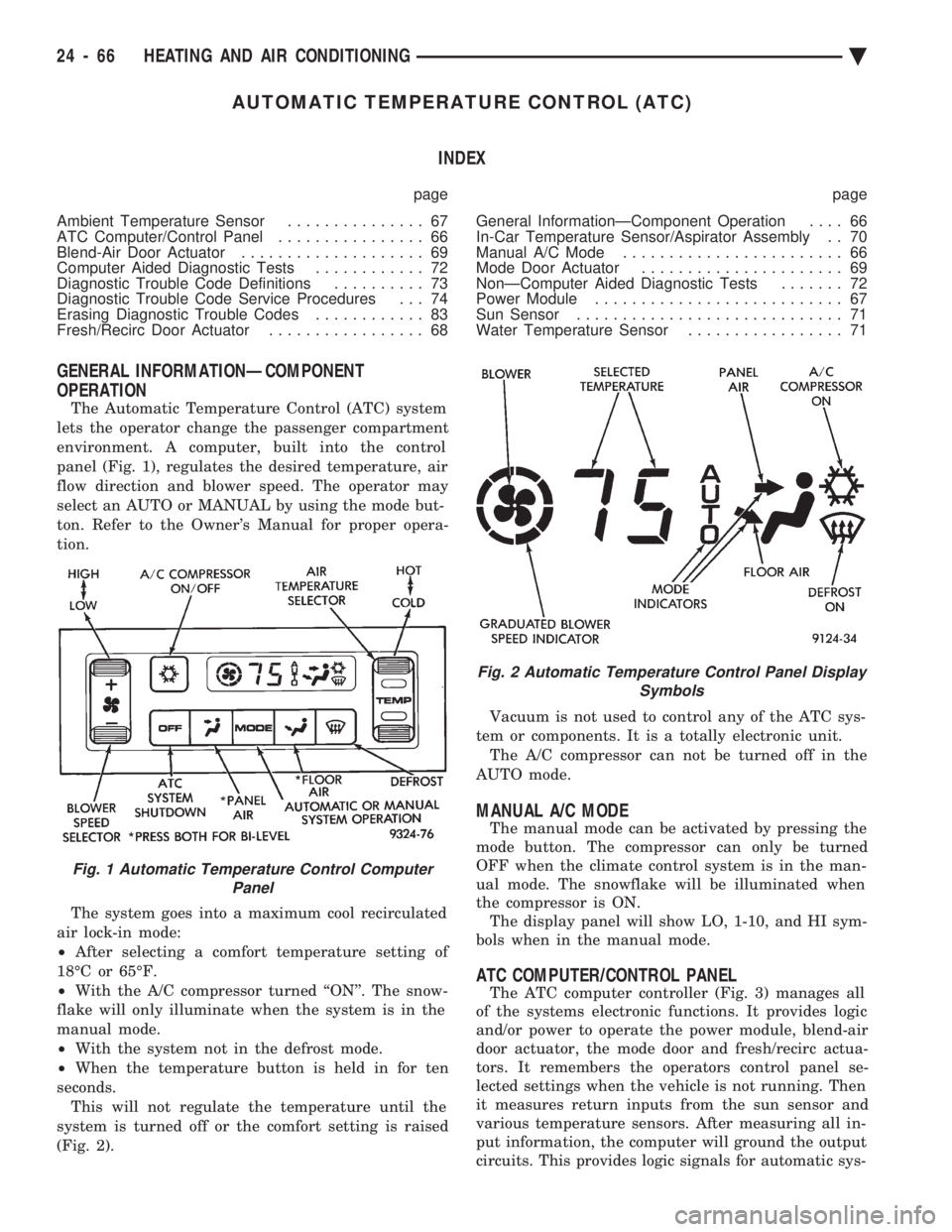
The Automatic Temperature Control (ATC) system
lets the operator change the passenger compartment
environment. A computer, built into the control
panel (Fig. 1), regulates the desired temperature, air
flow direction and blower speed. The operator may
select an AUTO or MANUAL by using the mode but-
ton. Refer to the Owner's Manual for proper opera-
tion.
The system goes into a maximum cool recirculated
air lock-in mode:
² After selecting a comfort temperature setting of
18ÉC or 65ÉF.
² With the A/C compressor turned ``ON''. The snow-
flake will only illuminate when the system is in the
manual mode.
² With the system not in the defrost mode.
² When the temperature button is held in for ten
seconds. This will not regulate the temperature until the
system is turned off or the comfort setting is raised
(Fig. 2). Vacuum is not used to control any of the ATC sys-
tem or components. It is a totally electronic unit. The A/C compressor can not be turned off in the
AUTO mode.
MANUAL A/C MODE
The manual mode can be activated by pressing the
mode button. The compressor can only be turned
OFF when the climate control system is in the man-
ual mode. The snowflake will be illuminated when
the compressor is ON. The display panel will show LO, 1-10, and HI sym-
bols when in the manual mode.
ATC COMPUTER/CONTROL PANEL
The ATC computer controller (Fig. 3) manages all
of the systems electronic functions. It provides logic
and/or power to operate the power module, blend-air
door actuator, the mode door and fresh/recirc actua-
tors. It remembers the operators control panel se-
lected settings when the vehicle is not running. Then
it measures return inputs from the sun sensor and
various temperature sensors. After measuring all in-
put information, the computer will ground the output
circuits. This provides logic signals for automatic sys-
Fig. 1 Automatic Temperature Control Computer Panel
Fig. 2 Automatic Temperature Control Panel Display Symbols
24 - 66 HEATING AND AIR CONDITIONING Ä
Page 2376 of 2438
NONÐCOMPUTER AIDED DIAGNOSTIC TESTS
Determine whether the operator complaint is due
to a system failure or improper operation of the ATC
system. The system will to go into a maximum heat
or cooling mode if the operator changes the tempera-
ture setting four or more degrees. Check the following:
² Coolant level
² Refrigerant charge
² Drive belt tension
² Radiator air flow
² Radiator fan operation
² Air suction of In-car Temperature Sensor/Aspirator
To check air suction of the Aspirator, place a small
piece of tissue paper over the Aspirator opening on
the instrument panel. This opening is located to the
right of the steering column. The tissue paper should
cling to the opening if system is functioning properly. Bring the engine to normal operating temperature
and proceed with Computer Aided Diagnostic Proce-
dures. Always test the entire system after each re-
pair has been performed.
COMPUTER AIDED DIAGNOSTIC TESTS
The ATC control has a computer capable of trou-
bleshooting the entire ATC system in approximately
60 seconds. The engine must be running and at nor-
mal operating temperature during the test to provide
hot coolant for the heater. During the ATC Diagnostic Test, the computer will
calibrate the Mode and Blend Door actuators.
CAUTION: Do not remove the actuators from the
heater-A/C unit assembly with power applied. Re-
moval should only be done with the Ignition OFF.
The actuators have no mechanical stops to limit the
travel. If the actuator rotates and is not connected
to the unit assembly, it will become un-calibrated.
The Diagnostic Test is capable of checking all elec-
trical signals between the ATC Control Module, ac-
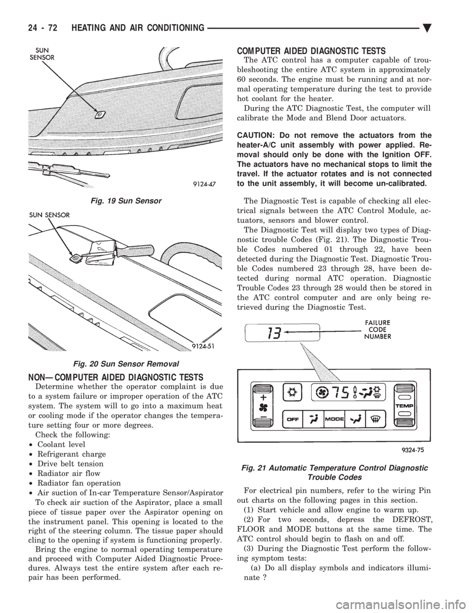
tuators, sensors and blower control. The Diagnostic Test will display two types of Diag-
nostic trouble Codes (Fig. 21). The Diagnostic Trou-
ble Codes numbered 01 through 22, have been
detected during the Diagnostic Test. Diagnostic Trou-
ble Codes numbered 23 through 28, have been de-
tected during normal ATC operation. Diagnostic
Trouble Codes 23 through 28 would then be stored in
the ATC control computer and are only being re-
trieved during the Diagnostic Test.
For electrical pin numbers, refer to the wiring Pin
out charts on the following pages in this section. (1) Start vehicle and allow engine to warm up.
(2) For two seconds, depress the DEFROST,
FLOOR and MODE buttons at the same time. The
ATC control should begin to flash on and off. (3) During the Diagnostic Test perform the follow-
ing symptom tests: (a) Do all display symbols and indicators illumi-
nate ?
Fig. 19 Sun Sensor
Fig. 20 Sun Sensor Removal
Fig. 21 Automatic Temperature Control Diagnostic Trouble Codes
24 - 72 HEATING AND AIR CONDITIONING Ä
Page 2377 of 2438
(b) Does the blower motor operate at its highest
speed ? (c) Feel the outlet temperature. Does it get hot
and then cycle cold ? (d) Does the air flow switch from DEFROST out-
lets and then cycle to PANEL outlets?
If you can answer NO to any of these questions,
proceed to step 4, otherwise proceed to step 5. (4) If you answered NO to:
SYMPTOM A
The display symbols and indicators do not illumi-
nate. Diagnostic Trouble Codes are not displayed.
TEST
After self-diagnostic test is complete, select a mode
that will display the malfunction.
ACTION
If the ATC system operates properly, and the dis-
play does not, replace ATC control panel computer.
SYMPTOM B
The blower motor does not operate.
CAUTION: Stay clear of blower motor and power
module (PM) heat sink. Do not run system for more
than 10 minutes with PM removed from A/C unit.
TEST Check all power module and blower motor connec-
tions. Use a voltmeter to test for 12 volts (ignition)
at both ends of the fuse with ignition ON. If fuse is
good, test the green wire at the blower motor connec-
tor for 12 volts (ignition) to body ground. Turn ignition to the ON position.
With the blower motor still connected, check for 12
volts to body ground on the black/tan wire of the
blower motor two way connector. Check for 12 volts at the Power Module pin #4
(BK/TN). Check for continuity from the Power Module pin
#3 (BK) to chassis ground. Replace the Power Module.
ACTION If 12 volts is not detected, repair feed circuit. Refer
to the Front Wheel Drive Car-Wiring Diagrams Ser-
vice Manual. If 12 volts is not detected, repair wires of the
blower motor or replace the blower motor. If 12 volts is not present, repair wire from the
blower motor connector to the Power Module. If circuit is open, repair ground circuit of the Power
Module. Replace the Power Module (power transistor open).
SYMPTOM C
The outlet air temperature does not become hot
and then cycle to cold during self-test operation. Di-
agnostic Trouble Codes are not displayed.
TEST/ACTION
Make sure the blend-air door is properly attached
to the actuator. If cold air is not discharged from the outlets, check
the base A/C refrigerant system. Make sure heating operation works correctly, (wa-
ter level, thermostat, heater hoses, heater core, etc.).
SYMPTOM D
Air does not flow from DEFROST outlets and then
cycle to PANEL outlets during self-test operation.
TEST/ACTION Check linkages from the mode door actuator for
binding. Check for proper door travel in the unit.
(5) The computer will do one of two things:
² Will return to the control settings that were se-
lected before the Diagnostic Test was started. This
means the test is over. If Diagnostic Trouble Codes
did not occur, and answers to questions (a), (b), (c),
and (d) were YES, the entire system is operating cor-
rectly.
² The blower motor will stop and the computer will
flash a Diagnostic Trouble Code number from 01
through 28. Record the number and then depress the
PANEL button to advance to the next test. If the
ATC control flashes one or more codes 23 to 28, the
digits on the display will flash alternating Zeros. If
you do nothing, these codes will remain stored within
the ATC control computer. After all repairs have
been made erase fault codes. Refer to Erasing Diag-
nostic Trouble Codes 23 through 28 from ATC Con-
trol in this section. Repair all Diagnostic Trouble Codes in the order
that they have been indicated, and then retest the
system. If any blend door test fails, all remaining
blend door tests will be skipped. IF any mode door
tests fail, all remaining mode door tests will be
skipped. Diagnostic Test can be stopped at any time by de-
pressing any button other than PANEL.
DIAGNOSTIC TROUBLE CODE DEFINITIONS
Non-computer aided diagnostics should be per-
formed first. Hood of vehicle should be closed during
the diagnostic test to keep engine heat from effecting
the ambient temperature sensor. Also refer to the wiring Pin out charts.
² DIAGNOSTIC TROUBLE CODE 1
Involves the wiring or the ATC control head.
² DIAGNOSTIC TROUBLE CODES 2, 13, 14, 15,
20, and 23
Ä HEATING AND AIR CONDITIONING 24 - 73