1993 CHEVROLET DYNASTY ECO mode
[x] Cancel search: ECO modePage 1812 of 2438
tween the flashes representing the first and second
digits of the code. Longer pauses separate individual
trouble codes.(3) Refer to the Diagnostic Trouble Code Charts at
the end of this group.
STATE DISPLAY TEST MODE
The switch inputs to the powertrain control module
(PCM) have two recognized states; HIGH and LOW.
For this reason, the PCM cannot recognize the differ-
ence between a selected switch position versus an
open circuit, a short circuit, or a defective switch. If
the State Display screen shows the change from
HIGH to LOW or LOW to HIGH, assume the entire
switch circuit to the PCM functions properly. From
the state display screen, access either State Display
Inputs and Outputs or State Display Sensors.
STATE DISPLAY INPUTS AND OUTPUTS
Connect the DRBII scan tool to the vehicle and ac-
cess the State Display screen. Then access Inputs and
Outputs. The following is a list of the engine control
system functions accessible through the Inputs and
Outputs screen.
² Park/Neutral Switch (automatic transaxle only)
² Speed Control Resume
² Speed Control On/Off
² Speed Control Set
² Brake Switch
² A/C Switch Sense
² S/C Vent Solenoid
² S/C Vacuum Solenoid
² A/C Clutch Relay
² Auto Shutdown Relay
² Radiator Fan Relay
² (Duty Cycle) EVAP Purge Solenoid
² Malfunction Indicator (Check Engine) Lamp
STATE DISPLAY SENSORS
Connect the DRBII scan tool to the vehicle and ac-
cess the State Display screen. Then access Sensor
Display. The following is a list of the engine control
system functions accessible through the Sensor Dis-
play screen.
² Oxygen Sensor Signal
² Engine Coolant Temperature
² Engine Coolant Temp Sensor
² Throttle Position
² Minimum Throttle
² Battery Voltage
² MAP Sensor Reading
² Idle Air Control Motor Position
² Adaptive Fuel Factor
² Barometric Pressure
² Min Airflow Idle Spd (Speed)
² Engine Speed
² Fault #1 Key-On Info
² Module Spark Advance ²
Speed Control Target
² Fault #2 Key-on Info
² Fault #3 Key-on Info
² Speed Control Status
² Charging System Goal
² Theft Alarm Status
² Battery Temperature
² Flex Fuel (Methanol Concentration) Sensor Volt-
age
² Methanol Content (percentage)
² Map Sensor Voltage
² Vehicle Speed
² Oxygen Sensor State
² MAP Gauge Reading
² Throttle Opening (percentage)
² Total Spark Advance
CIRCUIT ACTUATION TEST MODE
The Circuit Actuation Test Mode checks for proper
operation of output circuits or devices the powertrain
control module (PCM) cannot internally recognize.
The PCM attempts to activate these outputs and al-
low an observer to verify proper operation. Most of
the tests provide an audible or visual indication of
device operation (click of relay contacts, fuel spray,
etc.). Except for intermittent conditions, if a device
functions properly during testing, assume the device,
its associated wiring, and driver circuit work cor-
rectly.
OBTAINING CIRCUIT ACTUATION TEST
Connect the DRBII scan tool to the vehicle and ac-
cess the Actuators screen. The following is a list of
the engine control system functions accessible
through Actuators screens. Subordinate screens for
each actuator test are also listed. Stop All Tests
Ignition Coil No. 1
Fuel Injector No. 1
Fuel Injector No. 2
Fuel Injector No. 3
Fuel Injector No. 4
Idle Air Control Motor Open/Close
Fuel System
Radiator Fan Relay
A/C Clutch Relay
Auto Shutdown Relay
EVAP Purge Solenoid
Speed Control Servo Solenoids
Generator Field
Tachometer Output
Torque Converter Clutch Solenoid
All Solenoids/Relays
Speed Control Vent Solenoid
Speed Control Vacuum Solenoid
ASD Fuel System Test
14 - 72 FUEL SYSTEMS Ä
Page 1819 of 2438
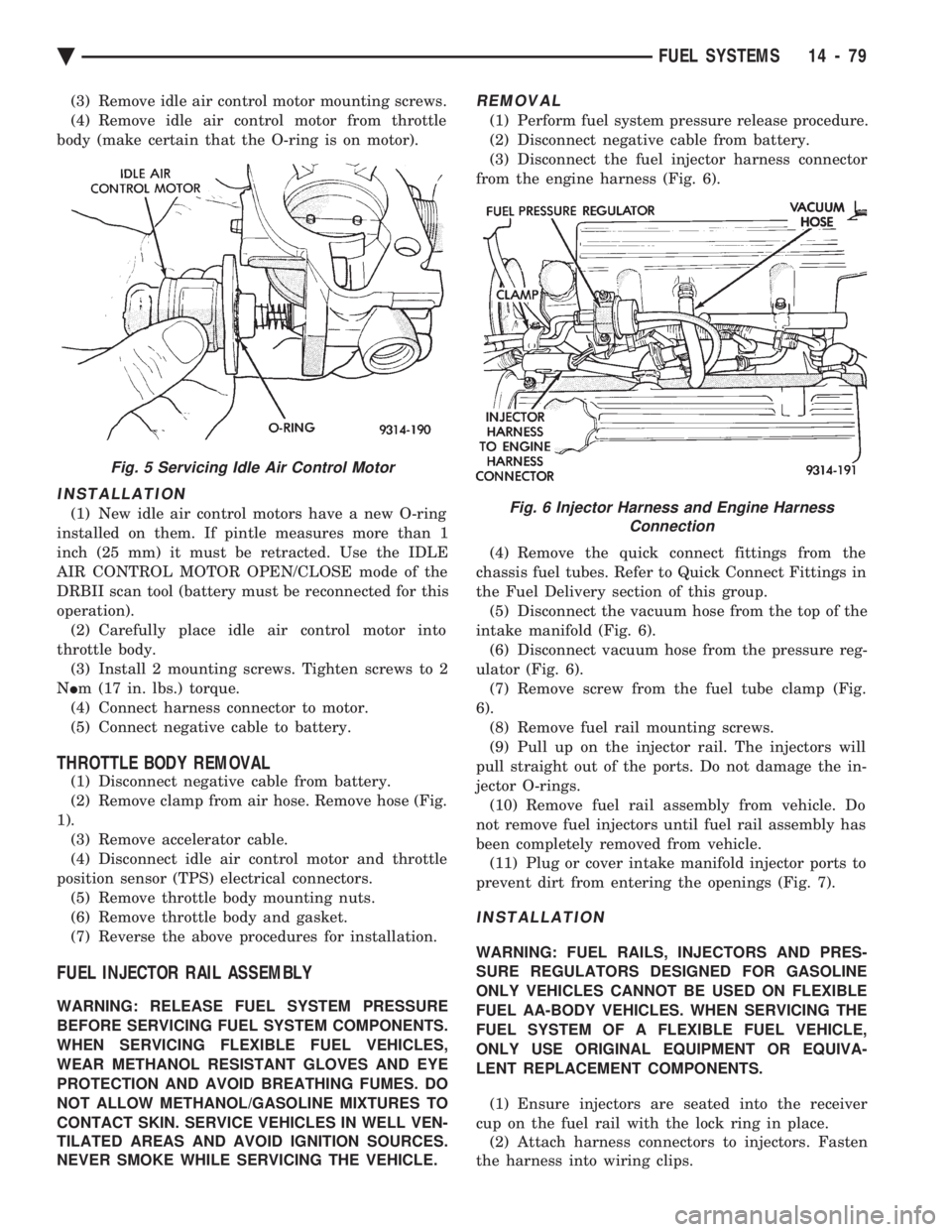
(3) Remove idle air control motor mounting screws.
(4) Remove idle air control motor from throttle
body (make certain that the O-ring is on motor).
INSTALLATION
(1) New idle air control motors have a new O-ring
installed on them. If pintle measures more than 1
inch (25 mm) it must be retracted. Use the IDLE
AIR CONTROL MOTOR OPEN/CLOSE mode of the
DRBII scan tool (battery must be reconnected for this
operation). (2) Carefully place idle air control motor into
throttle body. (3) Install 2 mounting screws. Tighten screws to 2
N Im (17 in. lbs.) torque.
(4) Connect harness connector to motor.
(5) Connect negative cable to battery.
THROTTLE BODY REMOVAL
(1) Disconnect negative cable from battery.
(2) Remove clamp from air hose. Remove hose (Fig.
1). (3) Remove accelerator cable.
(4) Disconnect idle air control motor and throttle
position sensor (TPS) electrical connectors. (5) Remove throttle body mounting nuts.
(6) Remove throttle body and gasket.
(7) Reverse the above procedures for installation.
FUEL INJECTOR RAIL ASSEMBLY
WARNING: RELEASE FUEL SYSTEM PRESSURE
BEFORE SERVICING FUEL SYSTEM COMPONENTS.
WHEN SERVICING FLEXIBLE FUEL VEHICLES,
WEAR METHANOL RESISTANT GLOVES AND EYE
PROTECTION AND AVOID BREATHING FUMES. DO
NOT ALLOW METHANOL/GASOLINE MIXTURES TO
CONTACT SKIN. SERVICE VEHICLES IN WELL VEN-
TILATED AREAS AND AVOID IGNITION SOURCES.
NEVER SMOKE WHILE SERVICING THE VEHICLE.
REMOVAL
(1) Perform fuel system pressure release procedure.
(2) Disconnect negative cable from battery.
(3) Disconnect the fuel injector harness connector
from the engine harness (Fig. 6).
(4) Remove the quick connect fittings from the
chassis fuel tubes. Refer to Quick Connect Fittings in
the Fuel Delivery section of this group. (5) Disconnect the vacuum hose from the top of the
intake manifold (Fig. 6). (6) Disconnect vacuum hose from the pressure reg-
ulator (Fig. 6). (7) Remove screw from the fuel tube clamp (Fig.
6). (8) Remove fuel rail mounting screws.
(9) Pull up on the injector rail. The injectors will
pull straight out of the ports. Do not damage the in-
jector O-rings. (10) Remove fuel rail assembly from vehicle. Do
not remove fuel injectors until fuel rail assembly has
been completely removed from vehicle. (11) Plug or cover intake manifold injector ports to
prevent dirt from entering the openings (Fig. 7).
INSTALLATION
WARNING: FUEL RAILS, INJECTORS AND PRES-
SURE REGULATORS DESIGNED FOR GASOLINE
ONLY VEHICLES CANNOT BE USED ON FLEXIBLE
FUEL AA-BODY VEHICLES. WHEN SERVICING THE
FUEL SYSTEM OF A FLEXIBLE FUEL VEHICLE,
ONLY USE ORIGINAL EQUIPMENT OR EQUIVA-
LENT REPLACEMENT COMPONENTS.
(1) Ensure injectors are seated into the receiver
cup on the fuel rail with the lock ring in place. (2) Attach harness connectors to injectors. Fasten
the harness into wiring clips.
Fig. 5 Servicing Idle Air Control Motor
Fig. 6 Injector Harness and Engine Harness Connection
Ä FUEL SYSTEMS 14 - 79
Page 1830 of 2438
sition, the PCM monitors the crankshaft position and
camshaft position sensor signals to determine engine
speed and ignition timing (coil dwell). If the PCM
does not receive the crankshaft position sensor and
camshaft position sensor signals when the ignition
switch is in the Run position, it de-energizes both re-
lays. When the relays are de-energized, battery volt-
age is not supplied to the fuel injector, ignition coil,
fuel pump and oxygen sensor heating element. The ASD relay and fuel pump relay are located in
the power distribution center (Fig. 16).
IDLE AIR CONTROL MOTORÐPCM OUTPUT
The idle air control motor is mounted on the throt-
tle body (Fig. 14). The PCM operates the motor. The
PCM adjusts engine idle speed through the idle air
control motor to compensate for engine load or ambi-
ent conditions. The throttle body has an air bypass passage that
provides air for the engine at idle (the throttle blade
is closed). The idle air control motor pintle protrudes
into the air bypass passage and regulates air flow
through it. The PCM adjusts engine idle speed by moving the
idle air control motor pintle in and out of the bypass
passage. The adjustments are based on inputs the
PCM receives. The inputs are from the throttle posi-
tion sensor, camshaft position sensor, crankshaft po-
sition sensor, coolant temperature sensor, and
various switch operations (brake and air condition-
ing). Deceleration die out is also prevented by in-
creasing airflow when the throttle is closed quickly
after a driving (speed) condition.
BAROMETRIC READ SOLENOIDÐPCM OUTPUT
The barometric pressure read solenoid is spliced
into the manifold absolute pressure (MAP) sensor
vacuum hose (Fig. 12). The barometric read solenoid
switches the pressure supply to the MAP sensor from
either barometric pressure (atmospheric) or manifold
vacuum. The PCM operates the solenoid. Atmospheric pressure is periodically supplied to
the MAP sensor to measure barometric pressure.
This occurs at closed throttle, once per throttle clo-
sure but no more often than once every 3 minutes
and within a specified RPM band. Barometric infor-
mation is used primarily for boost control and start
fuel enrichment at various altitudes.
CANISTER PURGE SOLENOIDÐPCM OUTPUT
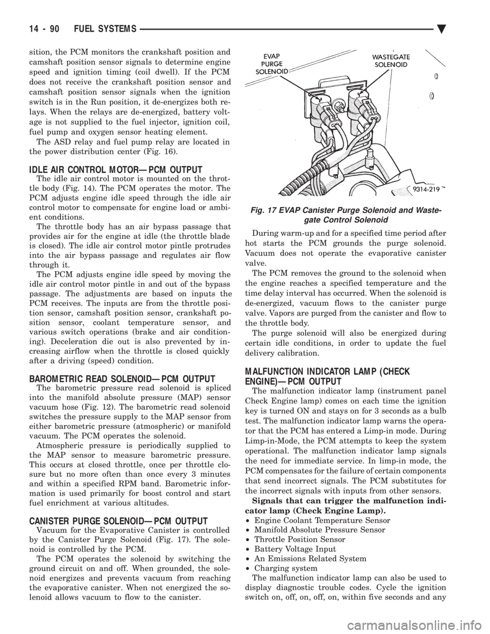
Vacuum for the Evaporative Canister is controlled
by the Canister Purge Solenoid (Fig. 17). The sole-
noid is controlled by the PCM. The PCM operates the solenoid by switching the
ground circuit on and off. When grounded, the sole-
noid energizes and prevents vacuum from reaching
the evaporative canister. When not energized the so-
lenoid allows vacuum to flow to the canister. During warm-up and for a specified time period after
hot starts the PCM grounds the purge solenoid.
Vacuum does not operate the evaporative canister
valve. The PCM removes the ground to the solenoid when
the engine reaches a specified temperature and the
time delay interval has occurred. When the solenoid is
de-energized, vacuum flows to the canister purge
valve. Vapors are purged from the canister and flow to
the throttle body. The purge solenoid will also be energized during
certain idle conditions, in order to update the fuel
delivery calibration.
MALFUNCTION INDICATOR LAMP (CHECK
ENGINE)ÐPCM OUTPUT
The malfunction indicator lamp (instrument panel
Check Engine lamp) comes on each time the ignition
key is turned ON and stays on for 3 seconds as a bulb
test. The malfunction indicator lamp warns the opera-
tor that the PCM has entered a Limp-in mode. During
Limp-in-Mode, the PCM attempts to keep the system
operational. The malfunction indicator lamp signals
the need for immediate service. In limp-in mode, the
PCM compensates for the failure of certain components
that send incorrect signals. The PCM substitutes for
the incorrect signals with inputs from other sensors. Signals that can trigger the malfunction indi-
cator lamp (Check Engine Lamp).
² Engine Coolant Temperature Sensor
² Manifold Absolute Pressure Sensor
² Throttle Position Sensor
² Battery Voltage Input
² An Emissions Related System
² Charging system
The malfunction indicator lamp can also be used to
display diagnostic trouble codes. Cycle the ignition
switch on, off, on, off, on, within five seconds and any
Fig. 17 EVAP Canister Purge Solenoid and Waste- gate Control Solenoid
14 - 90 FUEL SYSTEMS Ä
Page 1832 of 2438
noid is energized. The solenoid mounts to the passen-
ger side inner fender panel, next to the strut tower
(Fig. 17).
MODES OF OPERATION
As input signals to the PCM change, the PCM
adjusts its response to the output devices. For example,
the PCM must calculate a different injector pulse
width and ignition timing for idle than it does for wide
open throttle (WOT). There are several different modes
of operation that determine how the PCM responds to
the various input signals. There are two different areas of operation, OPEN
LOOP and CLOSED LOOP. During OPEN LOOP modes, the PCM receives input
signals and responds according to preset PCM pro-
gramming. Input from the oxygen (O
2) sensor is not
monitored during OPEN LOOP modes. During CLOSED LOOP modes, the PCM does moni-
tor the oxygen (O
2) sensor input. This input indicates
to the PCM whether or not the calculated injector pulse
width results in the ideal air-fuel ratio of 14.7 parts air
to 1 part fuel. By monitoring the exhaust oxygen
content through the O
2sensor, the PCM can fine tune
the injector pulse width to achieve optimum fuel
economy combined with low emissions. The 2.2L Turbo III multi-port fuel injection system
has the following modes of operation:
² Ignition switch ON - Zero RPM
² Engine start-up
² Engine warm-up
² Cruise (Idle)
² Acceleration
² Deceleration
² Wide Open Throttle
² Ignition switch OFF
The engine start-up (crank), engine warm-up, and
wide open throttle modes are OPEN LOOP modes. The
acceleration, deceleration, and cruise modes, with the
engine at operating temperature are CLOSED
LOOP modes (under most operating conditions).
IGNITION SWITCH ON (ZERO RPM) MODE
When the ignition switch activates the fuel injection
system the following actions occur:
²
The PCM calculates basic fuel strategy by determining
atmospheric air pressure from the MAP sensor input.
² The PCM monitors the coolant temperature sensor
and throttle position sensor input. The PCM modifies
fuel strategy based on this input. When the key is in the ON position and the engine is
not running, the auto shutdown (ASD) relay and fuel
pump relay are not energized. Therefore battery volt-
age is not supplied to the fuel pump, ignition coil, fuel
injector or oxygen sensor heating element.
ENGINE START-UP MODE
This is an OPEN LOOP mode. The following actions
occur when the starter motor is engaged. If the PCM receives the camshaft position and crank-
shaft position sensor signals, it energizes the auto
shutdown (ASD) relay and fuel pump relay. These
relays supply battery voltage to the fuel pump, fuel
injectors, ignition coil, and oxygen sensor heating ele-
ment. If the PCM does not receive the camshaft posi-
tion sensor and crankshaft position sensor signals
within approximately one second, it de-energizes the
ASD relay and fuel pump relay. The PCM energizes all injectors until it determines
crankshaft position from the camshaft position sensor
and crankshaft position sensor signals. The PCM de-
termines crankshaft position within 1 engine revolu-
tion. After determining crankshaft position, the PCM be-
gins energizing the injectors in sequence. The PCM
adjusts injector pulse width and controls injector syn-
chronization by turning the individual ground paths to
the injectors On and Off. When the engine idles within 664 RPM of its target
RPM, the PCM compares current MAP sensor value
with the atmospheric pressure value received during
the Ignition Switch On (zero RPM) mode. If the PCM
does not detect a minimum difference between the two
values, it sets a MAP fault into memory. Once the ASD and fuel pump relays have been
energized, the PCM:
² Determines injector pulse width based on coolant
temperature, manifold absolute pressure (MAP) and
the number of engine revolutions since cranking was
initiated.
² Monitors the coolant temperature sensor, camshaft
position sensor, crankshaft position sensor, MAP sen-
sor, and throttle position sensor to determine correct
ignition timing.
ENGINE WARM-UP MODE
This is a OPEN LOOP mode. The following inputs
are received by the PCM:
² engine coolant temperature
² knock sensor
² manifold absolute pressure (MAP)
² engine speed (crankshaft position sensor)
² throttle position
² A/C switch
² battery voltage
The PCM provides a ground path for the injectors to
precisely control injector pulse width (by switching the
ground on and off). The PCM adjusts engine idle speed
through the idle air control motor. Also, the PCM
regulates ignition timing.
14 - 92 FUEL SYSTEMS Ä
Page 1833 of 2438
CRUISE OR IDLE MODE
When the engine is at operating temperature, this is
a CLOSED LOOP mode. During cruising speed the
following inputs are received by the PCM:
² engine coolant temperature
² knock sensor
² manifold absolute pressure
² engine speed (crankshaft position sensor)
² throttle position
² exhaust gas oxygen content
² A/C control positions
² battery voltage
The PCM provides a ground path for the injectors to
precisely control injector pulse width. The PCM adjusts
engine idle speed and ignition timing. The PCM con-
trols the air/fuel ratio according to the oxygen content
in the exhaust gas.
ACCELERATION MODE
This is a CLOSED LOOP mode. The PCM recognizes
an abrupt increase in throttle position or MAP pres-
sure as a demand for increased engine output and
vehicle acceleration. The PCM increases injector pulse
width in response to increased fuel demand.
DECELERATION MODE
This is a CLOSED LOOP mode. During deceleration
the following inputs are received by the PCM:
² engine coolant temperature
² knock sensor
² manifold absolute pressure
² engine speed (crankshaft position sensor)
² throttle position
² exhaust gas oxygen content ²
A/C control positions
² battery voltage
The PCM may receive a closed throttle input from
the throttle position sensor (TPS) at the same time it
senses an abrupt decrease in manifold pressure. This
indicates a hard deceleration. The PCM modifies the
injector sequence. This helps maintain better control
of the air-fuel mixture.
WIDE OPEN THROTTLE MODE
This is an OPEN LOOP mode. During wide-open-
throttle operation, the following inputs are received
by the PCM:
² engine coolant temperature
² knock sensor
² manifold absolute pressure
² engine speed (crankshaft position sensor)
² throttle position
When the PCM senses a wide open throttle condi-
tion it will de-energize the air conditioning relay.
This disables the air conditioning system. The exhaust gas oxygen content input is not ac-
cepted by the PCM during wide open throttle opera-
tion. The PCM will enrichen the air/fuel ratio to
increase performance and compensate for increased
combustion chamber temperature.
IGNITION SWITCH OFF MODE
This is an OPEN LOOP mode. When the ignition
switch is turned to the OFF position, the following
occurs:
² All outputs are turned off.
² No inputs are monitored.
² The PCM shuts down.
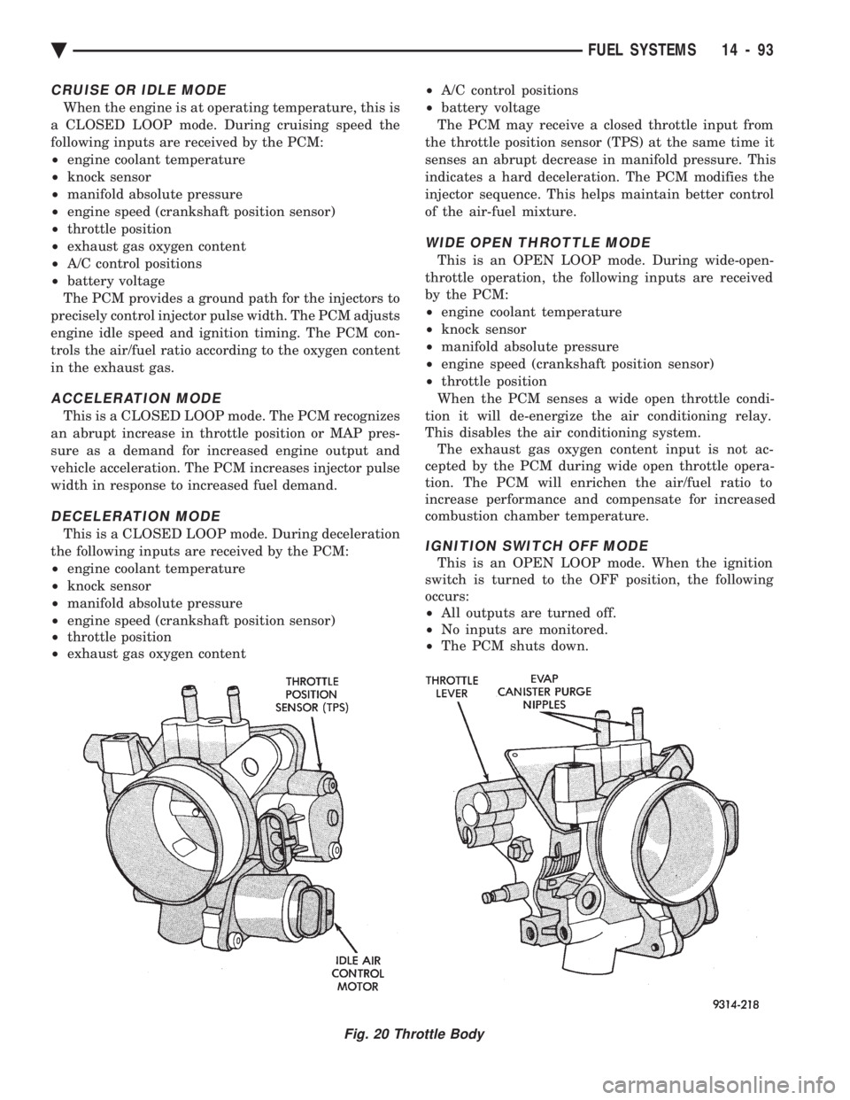
Fig. 20 Throttle Body
Ä FUEL SYSTEMS 14 - 93
Page 1844 of 2438
SYSTEM TESTS
Apply parking brake and/or block wheels be-
fore performing idle check or adjustment, or any
engine running tests.
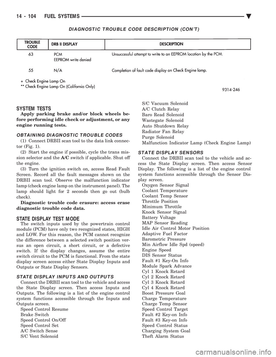
OBTAINING DIAGNOSTIC TROUBLE CODES
(1) Connect DRBII scan tool to the data link connec-
tor (Fig. 1). (2) Start the engine if possible, cycle the trans mis-
sion selector and the A/Cswitch if applicable. Shut off
the engine. (3) Turn the ignition switch on, access Read Fault
Screen. Record all the fault messages shown on the
DRBII scan tool. Observe the malfunction indicator
lamp (check engine lamp on the instrument panel). The
lamp should light for 2 seconds then go out (bulb
check). Diagnostic trouble code erasure: access erase
diagnostic trouble code data.
STATE DISPLAY TEST MODE
The switch inputs used by the powertrain control
module (PCM) have only two recognized states, HIGH
and LOW. For this reason, the PCM cannot recognize
the difference between a selected switch position ver-
sus an open circuit, a short circuit, or a defective
switch. If the display changes, assume the entire
switch circuit to the PCM is functional. From the state
display screen access either State Display Inputs and
Outputs or State Display Sensors.
STATE DISPLAY INPUTS AND OUTPUTS
Connect the DRBII scan tool to the vehicle and access
the State Display screen. Then access Inputs and
Outputs. The following is a list of the engine control
system functions accessible through the Inputs and
Outputs screen. Speed Control Resume
Brake Switch
Speed Control On/Off
Speed Control Set
A/C Switch Sense
S/C Vent Solenoid S/C Vacuum Solenoid
A/C Clutch Relay
Baro Read Solenoid
Wastegate Solenoid
Auto Shutdown Relay
Radiator Fan Relay
Purge Solenoid
Malfunction Indicator Lamp (Check Engine Lamp)
STATE DISPLAY SENSORS
Connect the DRBII scan tool to the vehicle and ac-
cess the State Display screen. Then access Sensor
Display. The following is a list of the engine control
system functions accessible through the Sensor Dis-
play screen. Oxygen Sensor Signal
Coolant Temperature
Coolant Temp Sensor
Throttle Position
Minimum Throttle
Knock Sensor Signal
Battery Voltage
MAP Sensor Reading
Idle Air Control Motor Position
Adaptive Fuel Factor
Barometric Pressure
Min Airflow Idle Spd (speed)
Engine Speed
DIS Sensor Status
Fault #1 Key-On Info
Module Spark Advance
Cyl 1 Knock Retard
Cyl 2 Knock Retard
Cyl 3 Knock Retard
Cyl 4 Knock Retard
Boost Pressure Goal
Charge Temperature
Charge Temp Sensor
Speed Control Target
Fault #2 Key-on Info
Fault #3 Key-on Info
Speed Control Status
Charging System Goal
Theft Alarm Status
DIAGNOSTIC TROUBLE CODE DESCRIPTION (CON'T)
14 - 104 FUEL SYSTEMS Ä
Page 1845 of 2438
Wastegate Duty Cycle
Battery Temperature
Map Sensor Voltage
Vehicle Speed
Oxygen Sensor State
Baro Read Update
MAP Gauge Reading
Throttle Opening (percentage)
Total Spark Advance
CIRCUIT ACTUATION TEST MODE
The purpose of the circuit actuation test mode is to
check for the proper operation of output circuits or
devices which the powertrain control module (PCM)
cannot internally recognize. The PCM can attempt to
activate these outputs and allow an observer to ver-
ify proper operation. Most of the tests available in
this mode provide an audible or visual indication of
device operation (click of relay contacts, spray fuel,
etc.). With the exception of an intermittent condition,
if a device functions properly during its test, assume
the device, its associated wiring, and its driver cir-
cuit are in working order.
OBTAINING CIRCUIT ACTUATION TEST
Connect the DRBII scan tool to the vehicle and ac-
cess the Actuators screen. The following is a list of
the engine control system functions accessible
through Actuators screens. Stop All Tests
Ignition Coil #1
Ignition Coil #2
Fuel Injector #1
Fuel Injector #2
Fuel Injector #3
Idle Air Control Motor Open/Close
Radiator Fan Relay
A/C Clutch Relay
Auto Shutdown Relay
Purge Solenoid
S/C Serv Solenoids
Generator Field
Tachometer Output
Wastegate Solenoid
Baro Read Solenoid
All Solenoids/Relays
Speed Control Vent Solenoid
Speed Control Vacuum Solenoid
ASD Fuel System Test
Fuel Injector #4
THROTTLE BODY MINIMUM AIR FLOW CHECK
PROCEDURE
(1) Warm the engine in neutral until the cooling
fan has cycled on and off at least once. (2) Shut off engine.
(3) Hook-up Tachometer.
(4) Disconnect the PCV valve hose from the nipple
on the intake manifold. (5) Attach air metering fitting, special tool 6457
(0.125 inch orifice), to the intake manifold PCV nip-
ple. (6) Disconnect 3/16 inch manifold vacuum purge
line from the top of the throttle body. Cap the 3/16
inch throttle body nipple. (7) Connect DRBII scan tool.
(8) Restart engine. Allow engine to idle for at least
one minute. (9) Using the DRBII scan tool, access Min. Airflow
Idle Spd. The following will then occur:
² Idle air control motor will fully close.
² Idle spark advance will become fixed.
² Engine RPM will be displayed on the DRBII scan
tool. (10) Check idle RPM with tachometer, if idle RPM
is within the below specification then the throttle
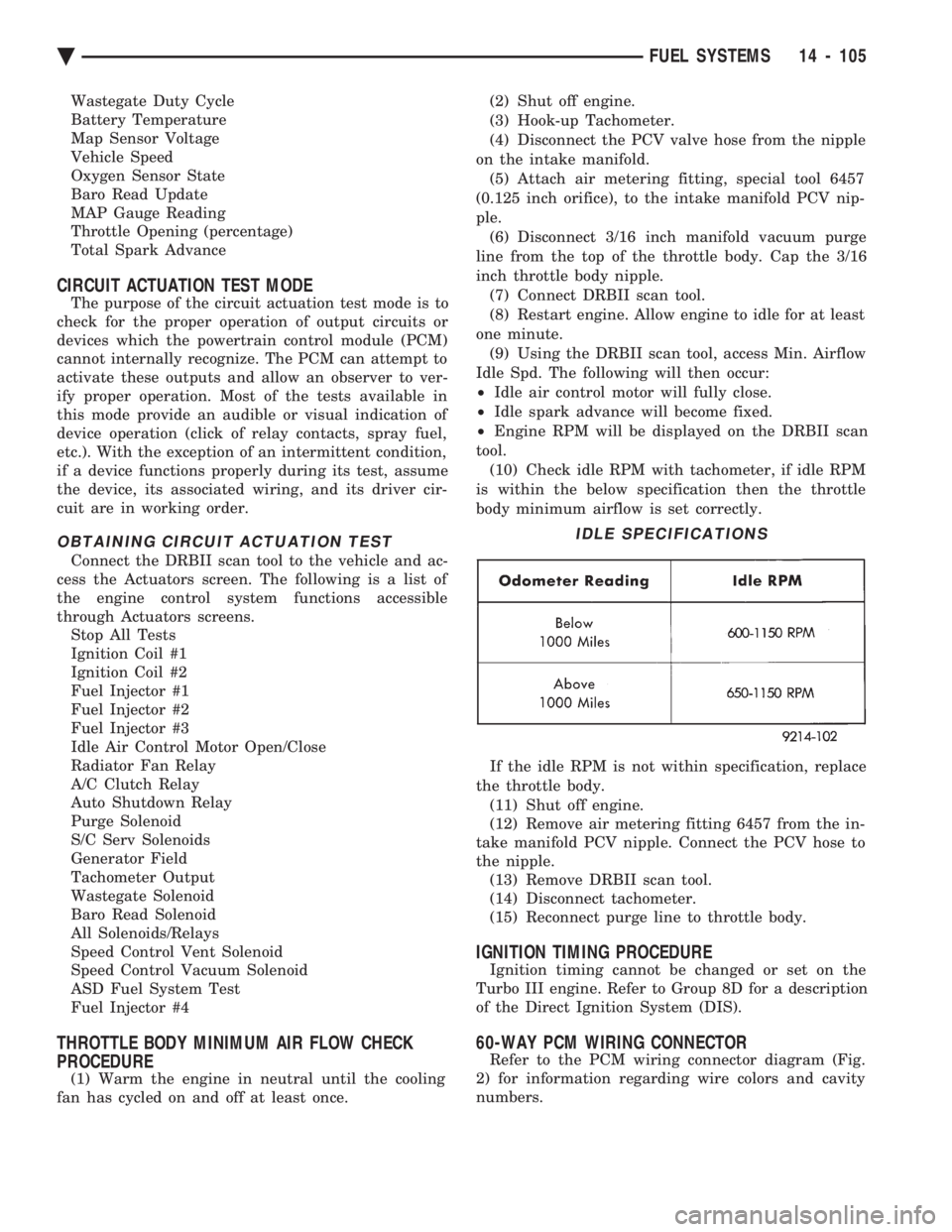
body minimum airflow is set correctly.
If the idle RPM is not within specification, replace
the throttle body. (11) Shut off engine.
(12) Remove air metering fitting 6457 from the in-
take manifold PCV nipple. Connect the PCV hose to
the nipple. (13) Remove DRBII scan tool.
(14) Disconnect tachometer.
(15) Reconnect purge line to throttle body.
IGNITION TIMING PROCEDURE
Ignition timing cannot be changed or set on the
Turbo III engine. Refer to Group 8D for a description
of the Direct Ignition System (DIS).
60-WAY PCM WIRING CONNECTOR
Refer to the PCM wiring connector diagram (Fig.
2) for information regarding wire colors and cavity
numbers.
IDLE SPECIFICATIONS
Ä FUEL SYSTEMS 14 - 105
Page 1860 of 2438
MALFUNCTION INDICATOR LAMP (CHECK ENGINE
LAMP)ÐPCM OUTPUT
The malfunction indicator lamp (instrument panel
Check Engine lamp) comes on each time the ignition
key is turned ON and stays on for 3 seconds as a bulb
test. The malfunction indicator lamp warns the opera-
tor that the PCM has entered a Limp-in mode. During
Limp-in Mode, the PCM attempts to keep the system
operational. The malfunction indicator lamp signals
the need for immediate service. In limp-in mode, the
PCM compensates for the failure of certain components
that send incorrect signals. The PCM substitutes for
the incorrect signals with inputs from other sensors. Signals that can trigger the malfunction indi-
cator lamp (Check Engine Lamp).
² Engine Coolant Temperature Sensor
² Manifold Absolute Pressure Sensor
² Throttle Position Sensor
² Battery Voltage Input
² An Emission Related System (California vehicles)
² Charging system
The malfunction indicator lamp displays diagnostic
trouble codes. Cycle the ignition switch on, off, on, off,
on, within five seconds to display any diagnostic
trouble codes stored in the PCM. Refer to the 3.0L
Multi-Port Fuel InjectionÐOn-Board Diagnostics sec-
tion of this Group for Diagnostic trouble code Descrip-
tions.
DATA LINK CONNECTORÐPCM OUTPUT
The data link connector provides the technician with
the means to connect the DRBII scan tool to diagnosis
the vehicle.
TRANSAXLE CONTROL MODULEÐPCM OUTPUT
The PCM supplies the following information to the
electronic automatic transaxle control module through
the CCD Bus:
² battery temperature ²
brake switch input
² engine coolant temperature
² manifold absolute pressure (MAP)
² speed control information
FUEL INJECTORSÐPCM OUTPUT
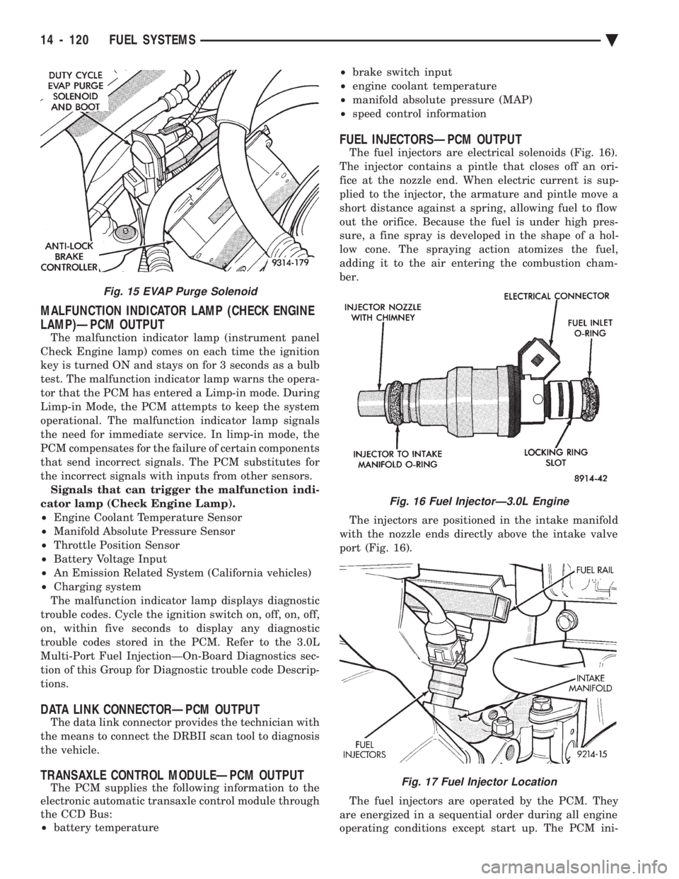
The fuel injectors are electrical solenoids (Fig. 16).
The injector contains a pintle that closes off an ori-
fice at the nozzle end. When electric current is sup-
plied to the injector, the armature and pintle move a
short distance against a spring, allowing fuel to flow
out the orifice. Because the fuel is under high pres-
sure, a fine spray is developed in the shape of a hol-
low cone. The spraying action atomizes the fuel,
adding it to the air entering the combustion cham-
ber.
The injectors are positioned in the intake manifold
with the nozzle ends directly above the intake valve
port (Fig. 16).
The fuel injectors are operated by the PCM. They
are energized in a sequential order during all engine
operating conditions except start up. The PCM ini-
Fig. 16 Fuel InjectorÐ3.0L Engine
Fig. 17 Fuel Injector Location
Fig. 15 EVAP Purge Solenoid
14 - 120 FUEL SYSTEMS Ä