1993 CHEVROLET DYNASTY manual transmission
[x] Cancel search: manual transmissionPage 1919 of 2438
STEERING
CONTENTS
page page
ACUSTAR STANDARD AND TILT STEERING COLUMN ............................ 28
AUTOMATIC TRANSMISSION SHIFTER/IGNITION INTERLOCK .......................... 36
GENERAL INFORMATION .................. 1 POWER STEERING GEAR
................ 25
POWER STEERING PUMPS ................ 1
SPECIFICATIONS AND TIGHTENING REFERENCE .......................... 42
GENERAL INFORMATION
Safety goggles should be worn at all times
when working on any steering gear or pump. Throughout this group, references may be made to
a particular vehicle by letter or number designation.
A chart showing the breakdown of these designations
is included in the Introduction Section at the front of
this service manual. The power steering system consists of these four
major components. Power Steering Pump, Power
Steering Gear, Pressure Hose, and Return Line.
Turning of the steering wheel is converted into lin-
ear travel through the meshing of the helical pinion teeth with the rack teeth. Power assist steering is
provided by an open center, rotary type control valve.
It is used to direct oil from the power steering pump
to either side of the integral steering rack piston. Road feel is controlled by the diameter of a torsion
bar which initially steers the vehicle. As steering ef-
fort increases as in a turn, the torsion bar twists,
causing relative rotary motion between the rotary
valve body and valve spool. This movement directs
oil behind the integral rack piston, which in turn,
builds up hydraulic pressure and assists in the turn-
ing effort.
POWER STEERING PUMPS
INDEX
page page
Checking Power Steering Fluid Level .......... 9
Flow Control Valve Fitting O-Ring Seal ........ 23
General Information ........................ 1
Power Steering Hoses ..................... 11
Power Steering Pressure Switch ............. 10
Power Steering Pump Fluid Reservoirs ........ 22 Power Steering Pump Pressure Test
........... 9
Power Steering Pump Pulley Service .......... 20
Power Steering Pump Removal .............. 12
Power Steering Pump Service ................ 2
Power Steering PumpÐInitial Operation ....... 24
Steering Components Service Diagnosis ........ 2
GENERAL INFORMATION
Hydraulic pressure for operation of the power
steering gear is provided by a belt driven power
steering pump. The power steering pump is a con-
stant flow rate and displacement, vane type pump.
Different styles of Saginaw power steering pumps are
used depending on the engine application of the ve-
hicle. On all four cylinder and 3.0-liter V-6 applications
the Saginaw Ham Can power steering pump is used
(Fig. 1). On the 3.3 & 3.8-liter V-6 and Turbo III applica-
tions, different versions of the Saginaw T/C style
power steering pump is used (Fig. 2). The 3.3 & 3.8 liter V-6 engine application uses the T/C style power
steering pump with a remote mounted reservoir for
the power steering fluid. On the Turbo III application
of the T/C style power steering pump, the power
steering fluid reservoir is integral to the power steer-
ing pump. On the integral reservoir type pump (Fig. 1) the
pump housing and internal components are combined
with the reservoir to form a one-piece mechanism. The Saginaw T/C style power steering pump (Fig.
2), consists of the power steering pump internal com-
ponents and pump housing. The Saginaw T/C style
power steering pump though has no internal reser-
voir for the power steering fluid. Depending on vehi-
Ä STEERING 19 - 1
Page 1937 of 2438
(18) Lower vehicle.
(19) Install the serpentine drive belt. Refer to (Fig.
10) for correct serpentine belt routing. See Cooling,
Group 7 for detailed installation procedure.
CAUTION: Do not use automatic transmission fluid
in power steering system. Only use Mopar T, Power
Steering Fluid, or equivalent.
(20) Fill power steering pump reservoir to correct
fluid level. (21) Connect the negative battery cable on the
negative battery post. (22) Start engine and turn steering wheel several
times from stop to stop to bleed air from fluid in sys-
tem. Stop engine, check fluid level, and inspect sys-
tem for leaks. See Checking Fluid Level.
TURBO III
REMOVE
(1) Disconnect the battery (-) negative cable from
the battery and isolate cable. (2) Raise vehicle See Hoisting, Group 0. Put oil
drain pan under vehicle to catch power steering
fluid. (3) Remove the right front underhood splash shield
for access to the serpentine belt tensioner. (4) Release the tension on the serpentine drive belt
tensioner and remove drive belt from power steering
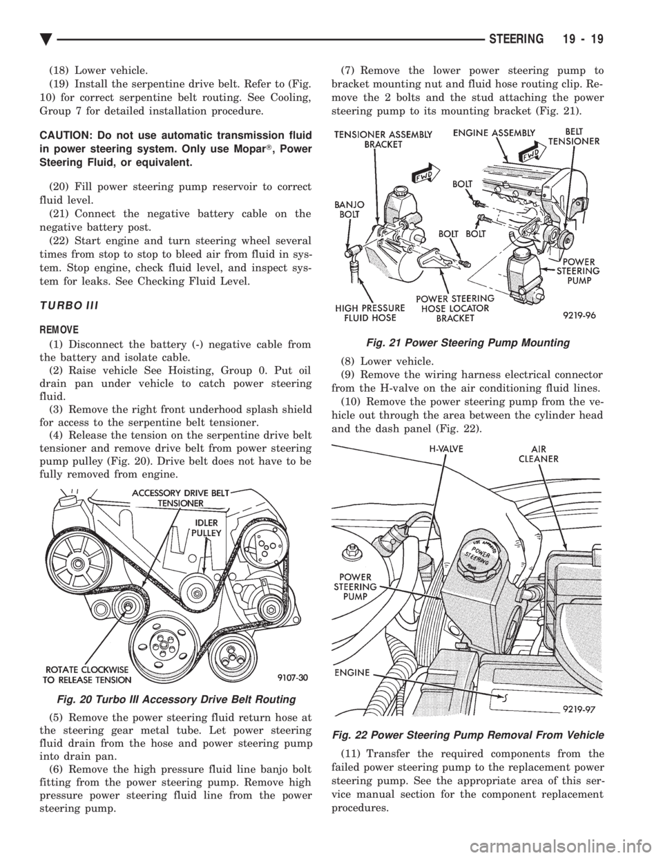
pump pulley (Fig. 20). Drive belt does not have to be
fully removed from engine.
(5) Remove the power steering fluid return hose at
the steering gear metal tube. Let power steering
fluid drain from the hose and power steering pump
into drain pan. (6) Remove the high pressure fluid line banjo bolt
fitting from the power steering pump. Remove high
pressure power steering fluid line from the power
steering pump. (7) Remove the lower power steering pump to
bracket mounting nut and fluid hose routing clip. Re-
move the 2 bolts and the stud attaching the power
steering pump to its mounting bracket (Fig. 21).
(8) Lower vehicle.
(9) Remove the wiring harness electrical connector
from the H-valve on the air conditioning fluid lines. (10) Remove the power steering pump from the ve-
hicle out through the area between the cylinder head
and the dash panel (Fig. 22).
(11) Transfer the required components from the
failed power steering pump to the replacement power
steering pump. See the appropriate area of this ser-
vice manual section for the component replacement
procedures.
Fig. 20 Turbo III Accessory Drive Belt Routing
Fig. 21 Power Steering Pump Mounting
Fig. 22 Power Steering Pump Removal From Vehicle
Ä STEERING 19 - 19
Page 1945 of 2438
bolts and nut on locating stud (Fig. 2). The right rear
crossmember stud is a pilot that correctly locates
the crossmember. Tighten down this bolt first,
then torque all 4 crossmember fasteners to 122
N Im (90 ft. lbs.).
CAUTION: Proper torque on the crossmember to
frame rail mounting bolts is very important.
(3) Torque the 4 bolts (Fig. 3) attaching the steering
gear assembly to front crossmember, to 68 N Im (50 ft.
lbs.). To ensure proper alignment of the steering
gear tighten left front bolt first. (4) Attach the engine damper strut from the engine
to the crossmember (if so equipped). (5) Attach the fluid tubes (Fig. 3) from the power
steering pump to the fittings on the steering gear.
Torque the fluid pressure line to steering gear tube nut
to 31 N Im (275 in. lbs.).
(6) Mount the outer tie rod ends to the steering
knuckles. Install the tie rod end to steering knuckle
attaching nuts. Torque the tie rod end to steering
knuckle nuts to 52 N Im (38 ft. lbs.). Install cotter pin
in tie rod end. (7) Install the front tire and wheel assemblies on
vehicle. Install the wheel lug nuts and torque to 129
N Im (95 ft. lbs.).
(8) Lower vehicle.
CAUTION: Do not use automatic transmission fluid. (9) Fill power steering pump fluid reservoir to the
(Full-Cold) proper level. (10) Start the engine and let run for a few seconds.
Then turn the engine off.
(11) Add fluid if necessary.
(12) Raise front wheels of vehicle off the ground.
(13) Start engine and turn steering wheel several
times from stop to stop to bleed air from fluid in
system. Stop engine, check fluid level, and inspect
system for leaks. Fill pump reservoir to correct
level with Mopar t, Power Steering Fluid, or
equivalent. See Checking Fluid Level.
(14) Lower front wheels of vehicle back on the
ground. (15) Adjust toe (Refer to Group 2 Suspension).
OUTER TIE ROD
REMOVAL
(1) Loosen inner tie rod to outer tie rod jam nut (Fig.
4). (2) Remove outer tie rod to steering knuckle cotter
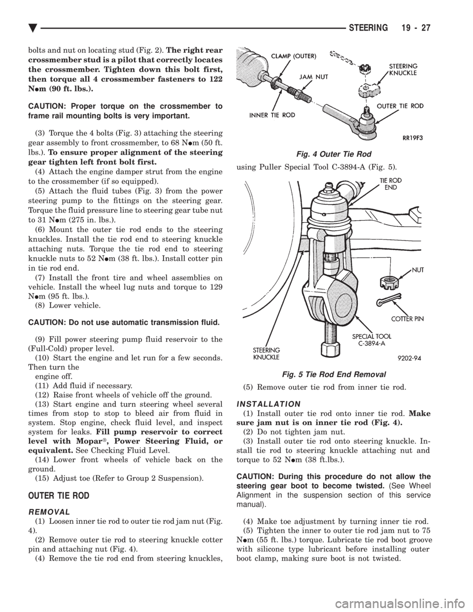
pin and attaching nut (Fig. 4). (4) Remove the tie rod end from steering knuckles, using Puller Special Tool C-3894-A (Fig. 5).
(5) Remove outer tie rod from inner tie rod.
INSTALLATION
(1) Install outer tie rod onto inner tie rod. Make
sure jam nut is on inner tie rod (Fig. 4). (2) Do not tighten jam nut.
(3) Install outer tie rod onto steering knuckle. In-
stall tie rod to steering knuckle attaching nut and
torque to 52 N Im (38 ft.lbs.).
CAUTION: During this procedure do not allow the
steering gear boot to become twisted. (See Wheel
Alignment in the suspension section of this service
manual).
(4) Make toe adjustment by turning inner tie rod.
(5) Tighten the inner to outer tie rod jam nut to 75
N Im (55 ft. lbs.) torque. Lubricate tie rod boot groove
with silicone type lubricant before installing outer
boot clamp, making sure boot is not twisted.
Fig. 4 Outer Tie Rod
Fig. 5 Tie Rod End Removal
Ä STEERING 19 - 27
Page 1954 of 2438
AUTOMATIC TRANSMISSION SHIFTER/IGNITION INTERLOCK INDEX
page page
General Information ....................... 36
Interlock System Adjustment ................ 37 Interlock System Operation Check
............ 36
Shifter/Ignition Interlock Cable ............... 38
GENERAL INFORMATION
The automatic transmission Shifter/Ignition Inter-
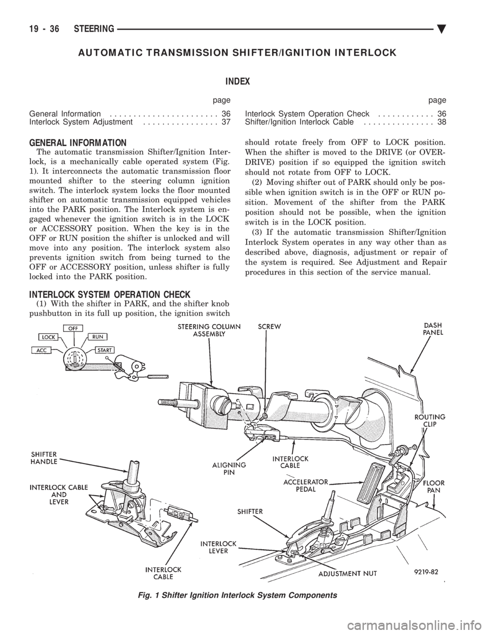
lock, is a mechanically cable operated system (Fig.
1). It interconnects the automatic transmission floor
mounted shifter to the steering column ignition
switch. The interlock system locks the floor mounted
shifter on automatic transmission equipped vehicles
into the PARK position. The Interlock system is en-
gaged whenever the ignition switch is in the LOCK
or ACCESSORY position. When the key is in the
OFF or RUN position the shifter is unlocked and will
move into any position. The interlock system also
prevents ignition switch from being turned to the
OFF or ACCESSORY position, unless shifter is fully
locked into the PARK position.
INTERLOCK SYSTEM OPERATION CHECK
(1) With the shifter in PARK, and the shifter knob
pushbutton in its full up position, the ignition switch should rotate freely from OFF to LOCK position.
When the shifter is moved to the DRIVE (or OVER-
DRIVE) position if so equipped the ignition switch
should not rotate from OFF to LOCK. (2) Moving shifter out of PARK should only be pos-
sible when ignition switch is in the OFF or RUN po-
sition. Movement of the shifter from the PARK
position should not be possible, when the ignition
switch is in the LOCK position. (3) If the automatic transmission Shifter/Ignition
Interlock System operates in any way other than as
described above, diagnosis, adjustment or repair of
the system is required. See Adjustment and Repair
procedures in this section of the service manual.
Fig. 1 Shifter Ignition Interlock System Components
19 - 36 STEERING Ä
Page 1962 of 2438
A-568 HEAVYÐDUTY MANUAL TRANSAXLE
The greater torque of the high output turbo engines
require a stronger transmission. It includes a die-cast
aluminum case and a stronger, coarse-pitch gear set. It
has five forward speed ratios and reverse. Gear ratios
are as follows: 1stÐ3.31, 2ndÐ1.89, 3rdÐ1.28,
4thÐ0.94, 5thÐ0.71, ReverseÐ3.14. Final drive ratio
of 3.85 was selected for maximum performance. All
forward gears are synchronized. To reduce wear, this transaxle, in common with other
manual transaxles, uses SAE 5W-30 engine oil as the
lubricant.
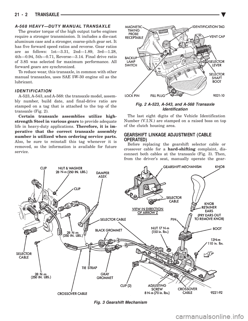
IDENTIFICATION
A-523, A-543, and A-568: the transaxle model, assem-
bly number, build date, and final-drive ratio are
stamped on a tag that is attached to the top of the
transaxle (Fig. 2). Certain transaxle assemblies utilize high-
strength Steel in various gears to provide adequate
life in heavy-duty applications. Therefore, it is im-
perative that the correct transaxle assembly
number is utilized when ordering service parts.
Also, be sure to reinstall this tag whenever it is
removed, so the information is available for future
service. The last eight digits of the Vehicle Identification
Number (V.I.N.) are stamped on a raised boss on top
of the clutch housing area.
GEARSHIFT LINKAGE ADJUSTMENT (CABLE
OPERATED)
Before replacing the gearshift selector cable or
crossover cable for a hard-shiftingcomplaint, dis-
connect both cables at the transaxle (Fig. 3). Then,
from the driver's seat, manually operate the gear-
Fig. 2 A-523, A-543, and A-568 Transaxle Identification
Fig. 3 Gearshift Mechanism
21 - 2 TRANSAXLE Ä
Page 2047 of 2438
OPERATION
The 41TE transaxle provides forward ratios of 2.84,
1.57, 1.00, and 0.69 with torque converter clutch
available in 2nd, direct, or overdrive gear; the Re-
verse ratio is 2.21. The shift lever is conventional
with six positions: P, R, N, OD, 3, and L. When OD
is selected the transaxle shifts normally through all
four speeds with torque converter clutch available in
overdrive; this position is recommended for most
driving. The 3 position is tailored for use in hilly or
mountainous driving. When 3 is selected, the trans-
mission uses only 1st, 2nd, and direct gears with
2nd-direct shift delayed to 40 mph or greater. When
operating in 3 or L positions torque converter clutch
application occurs in direct gear for improved trans-
mission cooling under heavy loads. If high engine
coolant temperature occurs, the torque converter
clutch will also engage in 2nd gear. The L position
provides maximum engine braking for descending
steep grades. Unlike most current transaxles, up-
shifts are provided to 2nd or direct gear at peak en-
gine speeds if the accelerator is depressed. This
provides engine over-speed protection and maximum
performance.
CLUTCH AND GEAR
The transaxle consists of:
² Three multiple disc input clutches
² Two multiple disc grounded clutches
² Four hydraulic accumulators
² Two planetary gear sets
This provides four forward ratios and a reverse ra-
tio. The clutch-apply pistons were designed with cen-
trifugally balanced oil cavities so that quick response
and good control can be achieved at any speed. A
push/pull piston is incorporated for two of the three
input clutches.
CAUTION: Some clutch packs appear similar, but
they are not the same. Do not interchange clutch
components as they might fail.
HYDRAULICS
The hydraulics of the transaxle provide the manual
shift lever select function, main line pressure regula-
tion, and torque converter and cooler flow control.
Oil flow to the friction elements is controlled directly
by four solenoid valves. The hydraulics also include a
unique logic-controlled ``solenoid torque converter
clutch control valve''. This valve locks out the 1st
gear reaction element with the application of 2nd, di-
rect, or overdrive gear elements. It also redirects the
1st gear solenoid output so that it can control torque
converter clutch operation. To regain access to 1st
gear, a special sequence of solenoid commands must
be used to unlock and move the solenoid torque con-
verter clutch control valve. This precludes any appli- cation of the 1st gear reaction element with other
elements applied. It also allows one solenoid to con-
trol two friction elements.
Small, high-rate accumulators are provided in each
controlled friction element circuit. These serve to ab-
sorb the pressure responses, and allow the controls to
read and respond to changes that are occurring.
SOLENOIDS
Since the solenoid valves perform virtually all con-
trol functions, these valves must be extremely dura-
ble and tolerant of normal dirt particles. For that
reason hardened-steel poppet and ball valves are
used. These are free from any close operating clear-
ances, and the solenoids operate the valves directly
without any intermediate element. Direct operation
means that these units must have very high output
so that they can close against the sizeable flow areas
and high line pressures. Fast response is also re-
quired to meet the control requirements. Two of the solenoids are normally-venting and two
are normally-applying; this was done to provide a de-
fault mode of operation. With no electrical power, the
transmission provides 2nd gear in OD, 3,orLshift
lever positions. All other transmission lever positions
will operate normally. The choice of 2nd gear was
made to provide adequate breakaway performance
while still accommodating highway speeds.
SENSORS
There are three pressure switches to identify sole-
noid application and two speed sensors to read input
(torque converter turbine) and output (parking sprag)
speeds. There is also a position switch to indicate the
manual shift lever position. The pressure switches
are incorporated in an assembly with the solenoids.
Engine speed, throttle position, temperature, etc., are
also observed. Some of these signals are read directly
from the engine control sensors; others are read from
a multiplex circuit with the powertrain control mod-
ule.
ELECTRONICS
The 41TE transmission control module is located
underhood in a potted, die-cast aluminum housing
with a sealed, 60-way connector.
ELECTRONIC MODULATED CONVERTER CLUTCH (EMCC)
The EMCC enables the torque converter clutch to
partially engage between 23 to 47 MPH before full
engagement at about 50 MPH and beyond. This fea-
ture is on all vehicles equipped with the 41TE tran-
saxle.
ADAPTIVE CONTROLS
These controls function by reading the input and
output speeds over 140 times a second and respond-
Ä TRANSAXLE 21 - 87
Page 2057 of 2438
first separator plate and watch carefully for the pis-
ton to move forward. The piston should return to its
original position after the air pressure is removed.
UNDERDRIVE CLUTCH
Because this clutch piston cannot be seen, its oper-
ation is checked by function. Air pressure is applied
to the low/reverse and the 2/4 clutches. This locks
the output shaft. Use a piece of rubber hose wrapped
around the input shaft and a pair of clamp-on pliers
to turn the input shaft. Next apply air pressure to
the underdrive clutch. The input shaft should not ro-
tate with hand torque. Release the air pressure and
confirm that the input shaft will rotate.
FLUID LEAKAGE-TORQUE CONVERTER HOUSING
AREA
(1) Check for source of leakage.
Since fluid leakage at or around the torque con-
verter area may originate from an engine oil leak,
the area should be examined closely. Factory fill
fluid is dyed red and, therefore, can be distinguished
from engine oil. (2) Prior to removing the transaxle, perform the
following checks: When leakage is determined to originate from the
transaxle, check fluid level prior to removal of the
transaxle and torque converter. High oil level can result in oil leakage out the vent
in the manual shaft. If the fluid level is high, adjust
to proper level. After performing this operation, inspect for leak-
age. If a leak persists, perform the following opera-
tion on the vehicle to determine if it is the torque
converter or transaxle that is leaking.
LEAKAGE TEST PROBE
(1) Remove torque converter housing dust shield.
(2) Clean the inside of torque converter housing
(lower area) as dry as possible. A solvent spray fol-
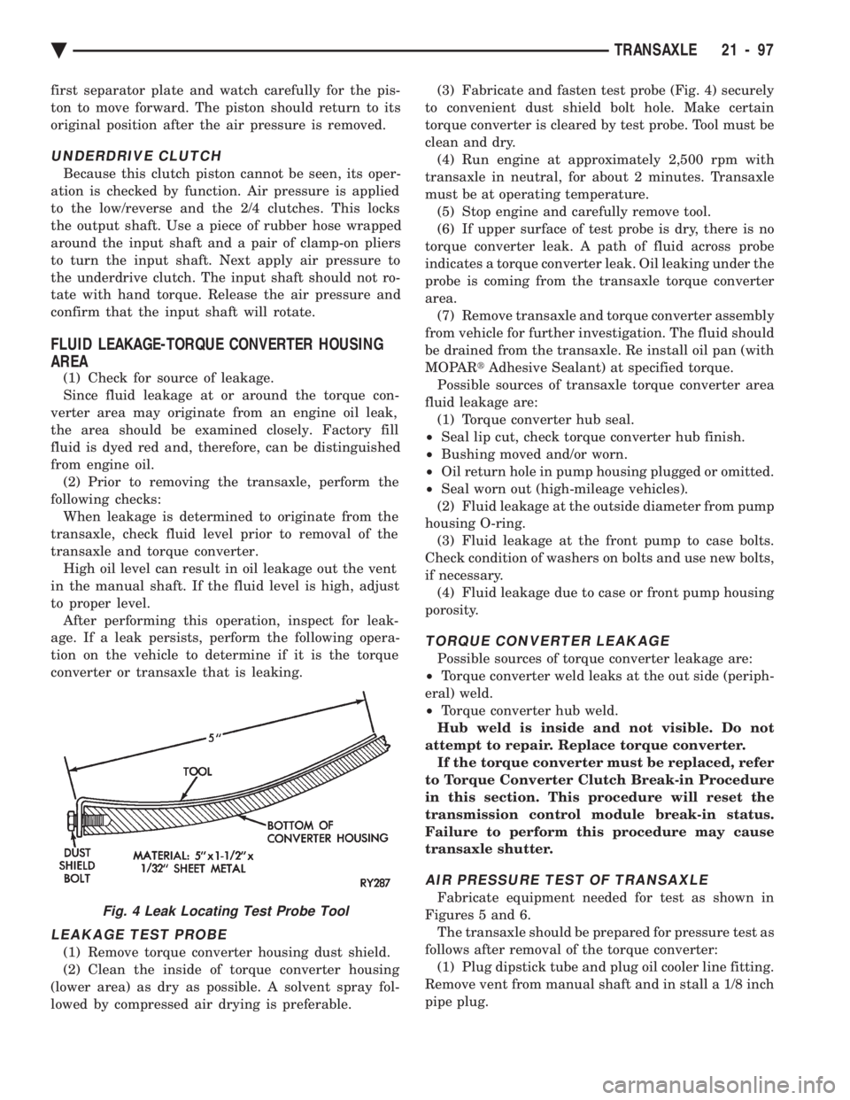
lowed by compressed air drying is preferable. (3) Fabricate and fasten test probe (Fig. 4) securely
to convenient dust shield bolt hole. Make certain
torque converter is cleared by test probe. Tool must be
clean and dry. (4) Run engine at approximately 2,500 rpm with
transaxle in neutral, for about 2 minutes. Transaxle
must be at operating temperature. (5) Stop engine and carefully remove tool.
(6) If upper surface of test probe is dry, there is no
torque converter leak. A path of fluid across probe
indicates a torque converter leak. Oil leaking under the
probe is coming from the transaxle torque converter
area. (7) Remove transaxle and torque converter assembly
from vehicle for further investigation. The fluid should
be drained from the transaxle. Re install oil pan (with
MOPAR tAdhesive Sealant) at specified torque.
Possible sources of transaxle torque converter area
fluid leakage are: (1) Torque converter hub seal.
² Seal lip cut, check torque converter hub finish.
² Bushing moved and/or worn.
² Oil return hole in pump housing plugged or omitted.
² Seal worn out (high-mileage vehicles).
(2) Fluid leakage at the outside diameter from pump
housing O-ring. (3) Fluid leakage at the front pump to case bolts.
Check condition of washers on bolts and use new bolts,
if necessary. (4) Fluid leakage due to case or front pump housing
porosity.
TORQUE CONVERTER LEAKAGE
Possible sources of torque converter leakage are:
² Torque converter weld leaks at the out side (periph-
eral) weld.
² Torque converter hub weld.
Hub weld is inside and not visible. Do not
attempt to repair. Replace torque converter. If the torque converter must be replaced, refer
to Torque Converter Clutch Break-in Procedure
in this section. This procedure will reset the
transmission control module break-in status.
Failure to perform this procedure may cause
transaxle shutter.
AIR PRESSURE TEST OF TRANSAXLE
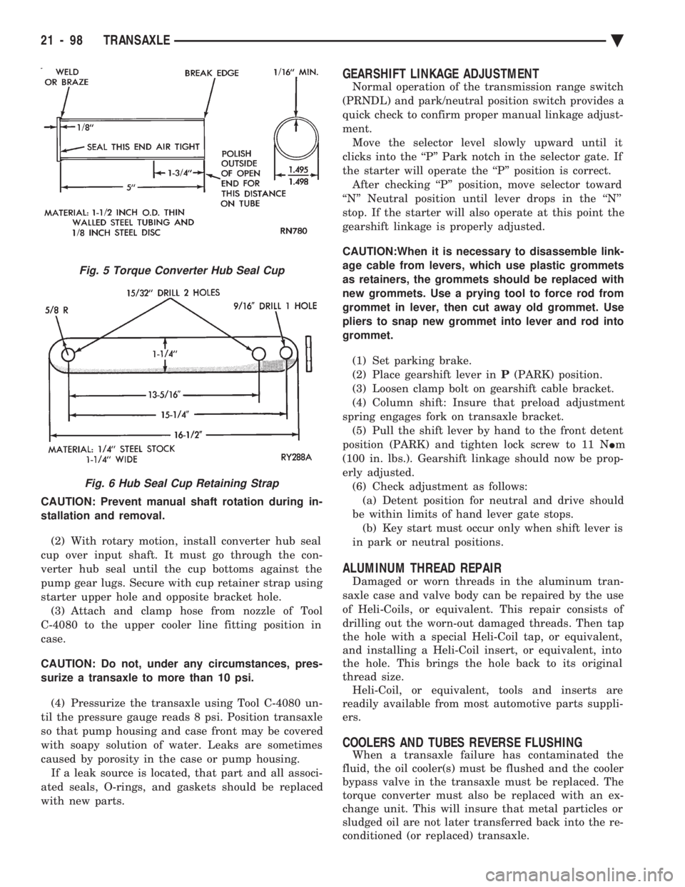
Fabricate equipment needed for test as shown in
Figures 5 and 6. The transaxle should be prepared for pressure test as
follows after removal of the torque converter: (1) Plug dipstick tube and plug oil cooler line fitting.
Remove vent from manual shaft and in stall a 1/8 inch
pipe plug.Fig. 4 Leak Locating Test Probe Tool
Ä TRANSAXLE 21 - 97
Page 2058 of 2438
CAUTION: Prevent manual shaft rotation during in-
stallation and removal. (2) With rotary motion, install converter hub seal
cup over input shaft. It must go through the con-
verter hub seal until the cup bottoms against the
pump gear lugs. Secure with cup retainer strap using
starter upper hole and opposite bracket hole. (3) Attach and clamp hose from nozzle of Tool
C-4080 to the upper cooler line fitting position in
case.
CAUTION: Do not, under any circumstances, pres-
surize a transaxle to more than 10 psi.
(4) Pressurize the transaxle using Tool C-4080 un-
til the pressure gauge reads 8 psi. Position transaxle
so that pump housing and case front may be covered
with soapy solution of water. Leaks are sometimes
caused by porosity in the case or pump housing. If a leak source is located, that part and all associ-
ated seals, O-rings, and gaskets should be replaced
with new parts.
GEARSHIFT LINKAGE ADJUSTMENT
Normal operation of the transmission range switch
(PRNDL) and park/neutral position switch provides a
quick check to confirm proper manual linkage adjust-
ment. Move the selector level slowly upward until it
clicks into the ``P'' Park notch in the selector gate. If
the starter will operate the ``P'' position is correct. After checking ``P'' position, move selector toward
``N'' Neutral position until lever drops in the ``N''
stop. If the starter will also operate at this point the
gearshift linkage is properly adjusted.
CAUTION:When it is necessary to disassemble link-
age cable from levers, which use plastic grommets
as retainers, the grommets should be replaced with
new grommets. Use a prying tool to force rod from
grommet in lever, then cut away old grommet. Use
pliers to snap new grommet into lever and rod into
grommet.
(1) Set parking brake.
(2) Place gearshift lever in P(PARK) position.
(3) Loosen clamp bolt on gearshift cable bracket.
(4) Column shift: Insure that preload adjustment
spring engages fork on transaxle bracket. (5) Pull the shift lever by hand to the front detent
position (PARK) and tighten lock screw to 11 N Im
(100 in. lbs.). Gearshift linkage should now be prop-
erly adjusted. (6) Check adjustment as follows:(a) Detent position for neutral and drive should
be within limits of hand lever gate stops. (b) Key start must occur only when shift lever is
in park or neutral positions.
ALUMINUM THREAD REPAIR
Damaged or worn threads in the aluminum tran-
saxle case and valve body can be repaired by the use
of Heli-Coils, or equivalent. This repair consists of
drilling out the worn-out damaged threads. Then tap
the hole with a special Heli-Coil tap, or equivalent,
and installing a Heli-Coil insert, or equivalent, into
the hole. This brings the hole back to its original
thread size. Heli-Coil, or equivalent, tools and inserts are
readily available from most automotive parts suppli-
ers.
COOLERS AND TUBES REVERSE FLUSHING
When a transaxle failure has contaminated the
fluid, the oil cooler(s) must be flushed and the cooler
bypass valve in the transaxle must be replaced. The
torque converter must also be replaced with an ex-
change unit. This will insure that metal particles or
sludged oil are not later transferred back into the re-
conditioned (or replaced) transaxle.
Fig. 5 Torque Converter Hub Seal Cup
Fig. 6 Hub Seal Cup Retaining Strap
21 - 98 TRANSAXLE Ä