1993 CHEVROLET DYNASTY oil level
[x] Cancel search: oil levelPage 258 of 2438

CAUTION: Do not insert dual function pressure
switch into hydraulic assembly using the socket
and ratchet. Cross threading of the switch may oc-
cur. (1) Install the dual function pressure switch into
the hydraulic assembly by hand until the O-ring
seals are seated. (2) Using Socket, Special Tool 6607, (Fig. 10)
torque the dual function pressure switch into the hy-
draulic assembly to 12 N Im (9 ft. lbs.).
(3) Connect the wiring harness connectors (Fig. 9)
onto the dual function pressure switch and the boost
pressure transducer. Be sure the locking tabs on the
connectors are fully engaged on the switches. (4) Lower the vehicle.
(5) Turn the ignition switch to the on position and
let the system pressurize. Check for any leaks at the
dual function pressure switch. (6) Fully de-pressurize the hydraulic assembly a
second time. This will purge any air out that may
have entered hydraulic assembly when the switch
was removed. Turn the ignition switch to the on po-
sition and let the system pressurize again. (7) Road test vehicle to insure that the brake sys-
tem is performing correctly.
PRIMARY PRESSURE TRANSDUCER
REMOVE
WARNING: FAILURE TO FULLY DE-PRESSURIZE
THE HYDRAULIC BLADDER ACCUMULATOR PRIOR
TO REMOVING PRIMARY PRESSURE TRANS-
DUCER. WILL RESULT IN PERSONAL INJURY
AND/OR DAMAGE TO PAINTED SURFACES OF THE
VEHICLE.
To remove primary pressure transducer (Fig. 11),
from hydraulic assembly, removal of hydraulic as-
sembly from vehicle is notrequired.
(1) Fully de-pressurize the hydraulic accumulator
by pumping brake pedal a minimum of 40 times. Use
procedure described in De-Pressurizing Hydraulic Ac-
cumulator listed earlier in this section. (2) Remove as much brake fluid as possible from
the brake fluid reservoir, using a syringe or equiva-
lent method. (3) Using oil filter band wrench, Special Tool
C-4065 or equivalent, (Fig. 12) loosen bladder accu-
mulator. Then remove bladder accumulator and
brake fluid spray shield from hydraulic assembly. (4) Remove high pressure banjo fitting (Fig. 13)
from hydraulic assembly. (5) Using needle nose pliers, remove the 3 fluid
reservoir retaining pins from the hydraulic assembly
(Fig. 14). Compress barb on opposite side of retaining
pin, to prevent pin from breaking. CAUTION: Be extremely careful during the following
procedure to avoid damaging or puncturing brake
fluid reservoir during its removal.
(6) Remove brake fluid reservoir from hydraulic
assembly by carefullyprying between reservoir and
hydraulic assembly using a blunt pry bar (Fig. 15).
Use a rocking motion to help disengage reservoir
from grommets while prying. (7) Remove brake fluid level sensor from reservoir
and remove fluid reservoir from vehicle. (8) Remove hydraulic assembly wiring harness
connector from the primary pressure transducer (Fig.
16).
Fig. 11 Primary Pressure Transducer Location On Hydraulic Assembly
Fig. 12 Removing Bladder Accumulator
5 - 108 ANTI-LOCK 10 BRAKE SYSTEM Ä
Page 276 of 2438
As soon as the condition goes away, the Anti-Lock
Warning Light is turned off. Although a fault code
will be set in most cases.
BENDIX ABS SYSTEMS DIAGNOSTICS
Bendix Anti-Lock 6 Brake System Diagnostics, be-
yond basic mechanical diagnostics, covered earlier in
this section. Are accomplished by using the DRB II
scan tool. See testing procedures outlined in the Ben-
dix Anti-Lock 6 Diagnostics Manual for the 1992
M.Y. vehicles. Please refer to the above mentioned manual for
any further electronic diagnostics and service proce-
dures that are required on the Bendix Anti-Lock 6
Brake System.
ON-CAR ABS BRAKE SYSTEM SERVICE
GENERAL SERVICE PRECAUTIONS
The following are general cautions which should be
observed when servicing the Anti-Lock brake system
and/or other vehicle systems. Failure to observe
these precautions may result in Anti-Lock Brake
System component damage. If welding work is to be performed on the vehicle,
using an electric arc welder, the (CAB) connector
should be disconnected during the welding operation. The (CAB) connector should never be connected or
disconnected with the ignition switch in the ON po-
sition. Many components of the Anti-Lock Brake System
are not serviceable and must be replaced as an as-
sembly. Do not disassemble any component which is
not designed to be serviced.
CHECKING BRAKE FLUID LEVEL
CAUTION: Only use brake fluid conforming to DOT
3 specifications, such as Mopar or Equivalent. Do
not use any fluid which contains a petroleum base.
Do not use a container which has been used for pe-
troleum based fluids or a container which is wet
with water. Petroleum based fluids will cause swell-
ing and distortion of rubber parts in the hydraulic
brake system. Water will mix with brake fluid, low-
ering the fluid boiling point. Keep all brake fluid
containers capped to prevent contamination. Re-
move the front cap of the master cylinder reservoir
and fill to the bottom of the split ring.
For the specific procedure for the inspection of
brake fluid level and adding of brake to the reser-
voir. Refer to the Service Adjustments Section in this
group of the service manual.
BLEEDING BENDIX ANTI-LOCK 6 BRAKE SYSTEM
The Anti-Lock Brake System must be bled anytime
air is permitted to enter the hydraulic system, due to
disconnection of brake lines, hoses of components. If the Modulator Assembly is removed from the ve-
hicle, both the Base Brake System and the Anti-Lock
Brake System must be bled using the appropriate
procedures. It is important to note that excessive air
in the brake system will cause a soft or spongy feel-
ing brake pedal. During bleeding operations, be sure that the brake
fluid level remains close to the FULL level in the
reservoir. Check the fluid level periodically during
the bleeding procedure and add DOT 3 brake fluid as
required. The Bendix Anti-Lock 6 Brake System must be
bled as two independent braking systems. The non
ABS portion of the brake system is to be bled the
same as any non ABS system. Refer to the Service
Adjustments section in this manual for the proper
bleeding procedure to be used. This brake system can
be either pressure bled or manually bled. The Anti-Lock portion of brake system MUST be
bled separately. This bleeding procedure requires the
use of the DRB II Diagnostic tester and the bleeding
sequence procedure outlined below.
ABS BLEEDING PROCEDURE (FIG. 1)
(1) Assemble and install all brake system compo-
nents on vehicle making sure all hydraulic fluid
lines are installed and properly torqued. (2) Bleed the base brake system. Using the stan-
dard pressure or manual bleeding procedure as out-
lined in the Service Adjustments section of this
service manual. To perform the bleeding procedure on the ABS
unit. The battery and acid shield must be removed
from the vehicle. Reconnect the vehicles battery, to
the vehicles positive and negative battery cables us-
ing jumper cables. This is necessary to allow access
to the 4 bleeder screws located on the top of the Mod-
ulator assembly. (3) Connect the DRB II Diagnostics Tester to the
diagnostics connector. Located behind the Fuse Panel
access cover on the lower section of the dash panel to
the left of the steering column. (It is a blue 6 way
connector). (4) Using the DRB II check to make sure the
(CAB) does not have any fault codes stored. If it does
remove them using the DRB II.
5 - 126 ANTI-LOCK 6 BRAKE SYSTEM Ä
Page 289 of 2438
SERVICE ADJUSTMENTS INDEX
page page
Bleeding Bendix Antilock 4 Brake System ....... 3
Master Cylinder Fluid Level .................. 3 Testing for Fluid Contamination
............... 4
MASTER CYLINDER FLUID LEVEL
Check master cylinder reservoir brake fluid level a
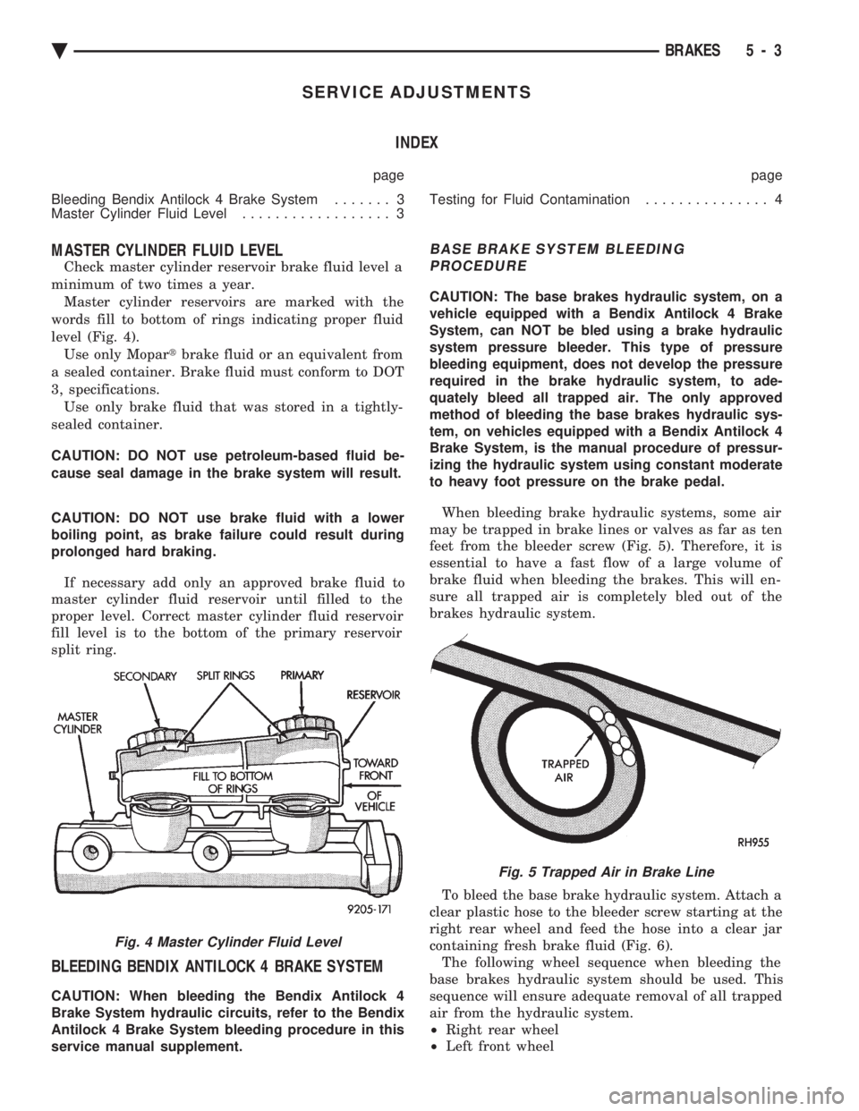
minimum of two times a year. Master cylinder reservoirs are marked with the
words fill to bottom of rings indicating proper fluid
level (Fig. 4). Use only Mopar tbrake fluid or an equivalent from
a sealed container. Brake fluid must conform to DOT
3, specifications. Use only brake fluid that was stored in a tightly-
sealed container.
CAUTION: DO NOT use petroleum-based fluid be-
cause seal damage in the brake system will result.
CAUTION: DO NOT use brake fluid with a lower
boiling point, as brake failure could result during
prolonged hard braking.
If necessary add only an approved brake fluid to
master cylinder fluid reservoir until filled to the
proper level. Correct master cylinder fluid reservoir
fill level is to the bottom of the primary reservoir
split ring.
BLEEDING BENDIX ANTILOCK 4 BRAKE SYSTEM
CAUTION: When bleeding the Bendix Antilock 4
Brake System hydraulic circuits, refer to the Bendix
Antilock 4 Brake System bleeding procedure in this
service manual supplement.
BASE BRAKE SYSTEM BLEEDING PROCEDURE
CAUTION: The base brakes hydraulic system, on a
vehicle equipped with a Bendix Antilock 4 Brake
System, can NOT be bled using a brake hydraulic
system pressure bleeder. This type of pressure
bleeding equipment, does not develop the pressure
required in the brake hydraulic system, to ade-
quately bleed all trapped air. The only approved
method of bleeding the base brakes hydraulic sys-
tem, on vehicles equipped with a Bendix Antilock 4
Brake System, is the manual procedure of pressur-
izing the hydraulic system using constant moderate
to heavy foot pressure on the brake pedal.
When bleeding brake hydraulic systems, some air
may be trapped in brake lines or valves as far as ten
feet from the bleeder screw (Fig. 5). Therefore, it is
essential to have a fast flow of a large volume of
brake fluid when bleeding the brakes. This will en-
sure all trapped air is completely bled out of the
brakes hydraulic system.
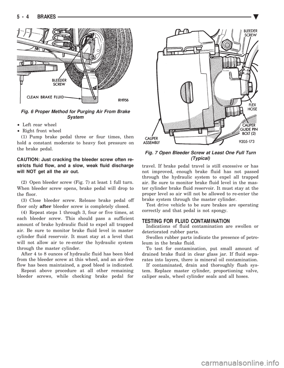
To bleed the base brake hydraulic system. Attach a
clear plastic hose to the bleeder screw starting at the
right rear wheel and feed the hose into a clear jar
containing fresh brake fluid (Fig. 6). The following wheel sequence when bleeding the
base brakes hydraulic system should be used. This
sequence will ensure adequate removal of all trapped
air from the hydraulic system.
² Right rear wheel
² Left front wheel
Fig. 4 Master Cylinder Fluid Level
Fig. 5 Trapped Air in Brake Line
Ä BRAKES 5 - 3
Page 290 of 2438
² Left rear wheel
² Right front wheel
(1) Pump brake pedal three or four times, then
hold a constant moderate to heavy foot pressure on
the brake pedal.
CAUTION: Just cracking the bleeder screw often re-
stricts fluid flow, and a slow, weak fluid discharge
will NOT get all the air out.
(2) Open bleeder screw (Fig. 7) at least 1 full turn.
When bleeder screw opens, brake pedal will drop to
the floor. (3) Close bleeder screw. Release brake pedal off
floor only afterbleeder screw is completely closed.
(4) Repeat steps 1 through 3, four or five times, at
each bleeder screw. This should pass a sufficient
amount of brake hydraulic fluid to expel all trapped
air. Be sure to monitor brake fluid level in master
cylinder fluid reservoir. It must stay at a level that
will not allow air to re-enter the hydraulic system
through the master cylinder. After 4 to 8 ounces of hydraulic fluid has been bled
from the bleeder screw at this wheel, and an air-free
flow has been maintained, a good bleed is indicated. Repeat above procedure at all other remaining
bleeder screws, while checking brake pedal for travel. If brake pedal travel is still excessive or has
not improved, enough brake fluid has not passed
through the hydraulic system to expel all trapped
air. Be sure to monitor brake fluid level in the mas-
ter cylinder brake fluid reservoir. It must stay at the
proper level so air will not be allowed to re-enter the
brake system through the master cylinder. Test drive vehicle to be sure brakes are operating
correctly and that pedal is not spongy.
TESTING FOR FLUID CONTAMINATION
Indications of fluid contamination are swollen or
deteriorated rubber parts. Swollen rubber parts indicate the presence of petro-
leum in the brake fluid. To test for contamination, put small amount of
drained brake fluid in clear glass jar. If fluid sepa-
rates into layers, there is mineral oil contamination. If contaminated, drain and thoroughly flush sys-
tem. Replace master cylinder, proportioning valve,
caliper seals, wheel cylinder seals and all hoses.
Fig. 6 Proper Method for Purging Air From Brake System
Fig. 7 Open Bleeder Screw at Least One Full Turn(Typical)
5 - 4 BRAKES Ä
Page 311 of 2438
LATCHING VERSUS NON-LATCHING ABS FAULTS
Some faults detected by the CAB are latching; the
fault is latched and ABS is disabled until the igni-
tion switch is reset. Thus ABS is disabled even if the
original fault has disappeared. Other faults are non-
latching; any warning lights that are turned on, are
only turned on as long as the fault condition exists.
As soon as the condition goes away, the Antilock
Warning Light is turned off. Although a fault code
will be set in most cases.
BENDIX ANTILOCK 4 BRAKE SYSTEM DIAGNOSTICS
Bendix Antilock 4 Brake System Diagnostics, be-
yond basic mechanical diagnostics, covered earlier in
this section, are accomplished by using the DRB scan
tool. See testing procedures outlined in the 1994 Ben-
dix Antilock 4 Diagnostics Manual. Please refer to the above mentioned manual for
any further electronic diagnostics and service proce-
dures that are required on the Bendix Antilock 4
Brake System.
ON-CAR ABS BRAKE SYSTEM SERVICE
GENERAL SERVICE PRECAUTIONS
The following are general cautions which should be
observed when servicing the Bendix Antilock 4
Brake System and other vehicle electronic systems.
Failure to observe these precautions may result in
Antilock Brake System component damage. If welding work is to be performed on a vehicle us-
ing an electric arc welder, disconnect the 60 way wir-
ing harness connector from the CAB, prior to
performing the welding operation. The wiring harness connector should never be con-
nected or disconnected from the CAB with the igni-
tion key in the ON or Run position. (3) Most components making up the assemblies of
the Bendix Antilock 4 Brake System can not be ser-
viced separately from those assemblies. This will re-
quire replacement of the complete assembly for the
servicing of these components. Do not disassemble
any component from an assembly which is desig-
nated as non-serviceable.
CHECKING BRAKE FLUID LEVEL
CAUTION: Only use brake fluid conforming to DOT
3 specifications, such as Mopar or Equivalent. Do
not use any fluid which contains a petroleum base.
Do not use a container which has been used for pe-
troleum based fluids or a container which is wet
with water. Petroleum based fluids will cause swell-
ing and distortion of rubber parts in the hydraulic
brake system. Water will mix with brake fluid, low-
ering the boiling point of the brake fluid, possibly causing brake fluid to boil resulting in brake fade.
Keep all brake fluid containers capped to prevent
contamination. Remove the front cap of the master
cylinder reservoir and fill to the bottom of the split
ring.
For the specific procedure for the inspection of
brake fluid level and adding of brake to the reser-
voir. Refer to the Service Adjustments Section in this
group of the service manual.
BLEEDING BENDIX ANTILOCK 4 BRAKE SYSTEM
The base brakes and Antilock Brake System must
be bled anytime air is permitted to enter the hydrau-
lic system, due to disconnection of brake lines, hoses
or components. If the Antilock Modulator Assembly is removed
from the vehicle, both the Base Brake System and
the Antilock Brake System must be bled using the
appropriate procedure. It is important to note that
excessive air in the brake system will cause a soft or
spongy feeling brake pedal. During brake bleeding operations, ensure that
brake fluid level remains close to the FULL level in
the reservoir. Check brake fluid level periodically
during bleeding procedure, adding DOT 3 brake fluid
as required.
CAUTION: The base brake and Antilock brake hy-
draulic systems, on the Bendix Antilock 4 Brake
System, can NOT be bled using any type of brake
pressure bleeding equipment. This type of bleeding
equipment does not develop the pressure required
in the brake hydraulic system, to adequately bleed
all trapped air. The only approved method for bleed-
ing air out of the hydraulic system on vehicles
equipped with the Bendix Antilock 4 Brake System,
is the manual procedure of pressurizing the hydrau-
lic system using constant, moderate to heavy foot
pressure on the brake pedal.
The Bendix Antilock 4 Brake System must be bled
as two independent brake systems. The non ABS por-
tion of the brake system is to be bled the same as
any non ABS system. Refer to the Service Adjust-
ments section in this manual for the proper bleeding
procedure to be used. The Bendix Antilock 4 Brake
System can only be bled using a manual method of
pressurizing the brakes hydraulic system. The Antilock portion of brake system MUST be
bled separately. This bleeding procedure requires the
use of the DRB Diagnostic tester and the bleeding se-
quence procedure outlined below.
Ä ANTILOCK 4 BRAKE SYSTEM 5 - 25
Page 343 of 2438
COOLING SYSTEM
CONTENTS
page page
ACCESSORY DRIVE BELTS ............... 24
ENGINE BLOCK HEATER ................. 28
GENERAL INFORMATION .................. 1 SERVICE PROCEDURES
.................. 10
SPECIFICATIONS ....................... 29
GENERAL INFORMATION
Throughout this group, references may be made to
a particular vehicle by letter or number designation.
A chart showing the breakdown of these designations
is included in the Introduction Section at the front of
this service manual.
COOLING SYSTEM
The cooling system consists of an engine cooling
module, thermostat, coolant, a water pump to circu-
late the coolant. The engine cooling module may con-
sist of a radiator, electric fan motor, shroud, radiator
pressure cap, coolant reserve system, transmission oil
cooler, hoses, clamps, air condition condenser, trans-
mission oil lines and charge air cooler.
² When Engine is cold: Thermostat is closed, cooling
system has no flow through the radiator. The coolant
bypass flows through the engine only. ²
When Engine is warm: Thermostat is open, cooling
system has bypass flow and coolant flow through ra-
diator. Its primary purpose is to maintain engine temper-
ature in a range that will provide satisfactory engine
performance and emission levels under all expected
driving conditions. It also provides hot water (cool-
ant) for heater performance and cooling for auto-
matic transmission oil. It does this by transferring
heat from engine metal to coolant, moving this
heated coolant to the radiator, and then transferring
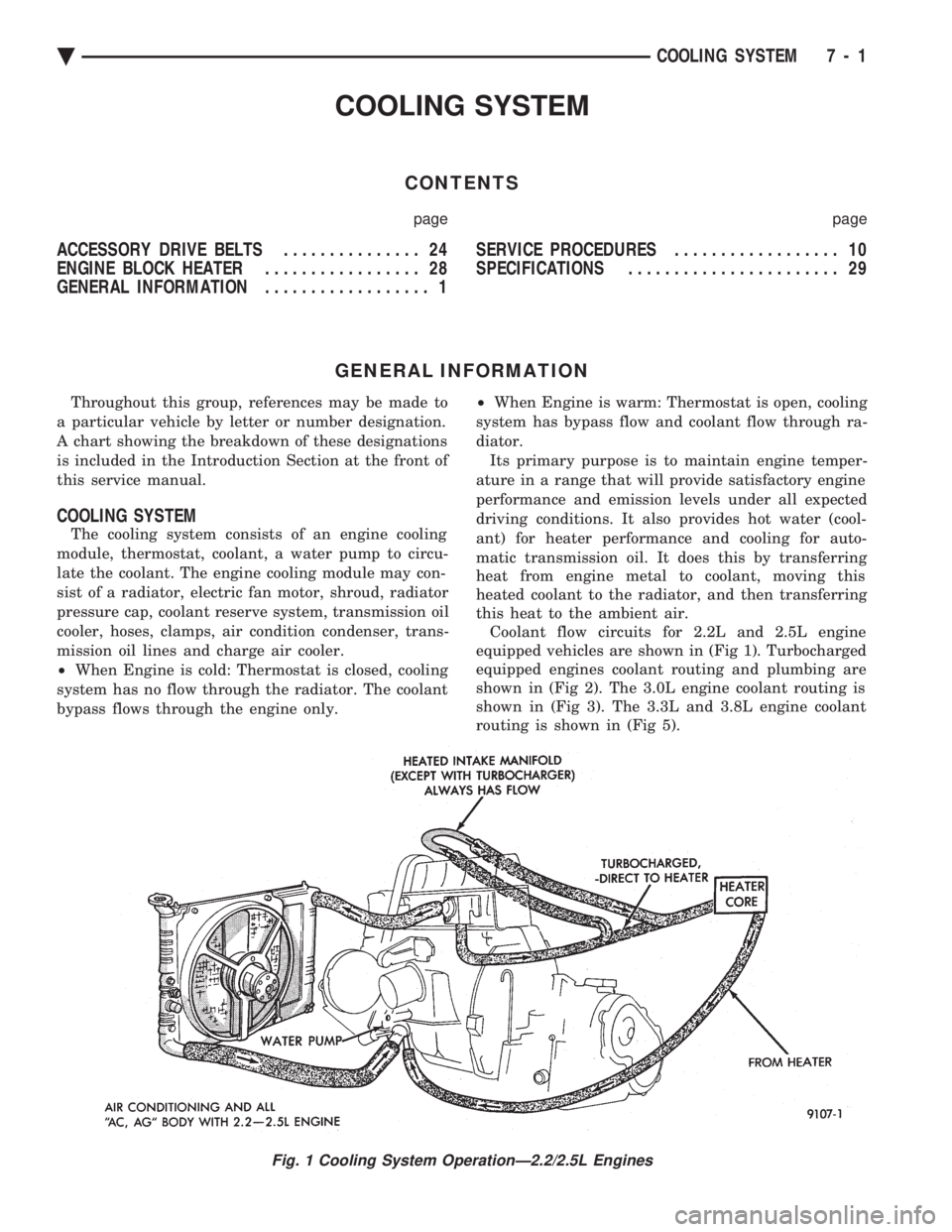
this heat to the ambient air. Coolant flow circuits for 2.2L and 2.5L engine
equipped vehicles are shown in (Fig 1). Turbocharged
equipped engines coolant routing and plumbing are
shown in (Fig 2). The 3.0L engine coolant routing is
shown in (Fig 3). The 3.3L and 3.8L engine coolant
routing is shown in (Fig 5).
Fig. 1 Cooling System OperationÐ2.2/2.5L Engines
Ä COOLING SYSTEM 7 - 1
Page 357 of 2438

-37ÉC (-35ÉF) to -59ÉC (-50ÉF). If it looses color or
becomes contaminated, drain, flush, and replace with
fresh properly mixed solution.
SERVICE
Coolant should be changed at 52,500 miles or three
years, whichever occurs first, then every two years or
30,000 miles.
ROUTINE LEVEL CHECK
Do not remove radiator cap for routine coolant
level inspections. The coolant reserve system provides a quick visual
method for determining the coolant level without re-
moving the radiator cap. Simply observe, with the
engine idling and warmed up to normal operating
temperature, that the level of the coolant in the reserve
tank (Figs. 5 and 6) is between the minimum and
maximum marks.
ADDING ADDITIONAL COOLANT
The radiator cap should not be removed. When
additional coolant is needed to maintain this level, it
should be added to the coolant reserve tank. Use only
50/50 concentration of ethylene glycol type antifreeze
and water.
SERVICE COOLANT LEVEL
The cooling system is closed and designed to main-
tain coolant level to the top of the radiator. When servicing requires a coolant level check in the
radiator, the engine must be offand notunder pres-
sure. Drain several ounces of coolant from the radiator
drain cock while observing the Coolant Recovery Sys-
tem (CRS) Tank. Coolant level in the CRS tank should
drop slightly. Then remove the radiator cap. The radia-
tor should be full to the top. If not, and the coolant level
in the CRS tank is at the MIN mark there is a air leak
in the CRS system. Check hose or hose connections to
the CRS tank, radiator filler neck or the pressure cap
seal to the radiator filler neck for leaks.
LOW COOLANT LEVEL AERATION
Low coolant level in a cross flow radiator will equal-
ize in both tanks with engine off. With engine at
running operating temperature the high pressure inlet
tank runs full and the low pressure outlet tank drops.
If this level drops below the top of the transmission oil
cooler, air will be sucked into the water pump:
² Transmission oil will become hotter.
² High reading shown on the temperature gauge.
² Air in the coolant will also cause loss of flow through
the heater.
² Exhaust gas leaks into the coolant can also cause the
same problems.
DEAERATION
Air can only be removed from the system by gather-
ing under the pressure cap. On the next heat up it will
be pushed past the pressure cap into the CRS tank by
thermal expansion of the coolant. It then escapes to the
atmosphere in the CRS tank and is replaced with solid
coolant on cool down.
COOLING SYSTEM DRAIN, CLEAN, FLUSH AND
REFILL
Drain, flush, and fill the cooling system at the
mileage or time intervals specified in the Maintenance
Schedule in this Group. If the solution is dirty or rusty
or contains a considerable amount of sediment, clean
and flush with a reliable cooling system cleaner. Care
should be taken in disposing of the used engine coolant
from your vehicle. Check governmental regulations for
disposal of used engine coolant.
DRAINING
To drain cooling system move temperature selector
for heater to full heat with engine running (to provide
vacuum for actuation). Without removing radiator
pressure cap and with system not under pres-
sure, Shut engine off and open draincock. The coolant
reserve tank (Fig. 5) should empty first, then remove
radiator pressure cap. (if not, see Testing Cooling
System for leaks). To vent 2.2/2.5L engines remove the
plug above thermostat housing (Fig. 1). For Turbo III
engines remove coolant temperature sensor in the
thermostat housing (Fig. 2). For 3.3L /3.8L engine
remove the engine temperature sending unit (Fig. 3).
Removal of a plug or other component is required
because the thermostat has no air vent and prevents
air flow through it. This allows the coolant to drain
from the engine block.
Fig. 1 Thermostat Housing Drain/Fill PlugÐ2.2/2.5L Engines
Ä COOLING SYSTEM 7 - 15
Page 359 of 2438
TESTING SYSTEM FOR LEAKS
With engine not running, wipe the radiator filler
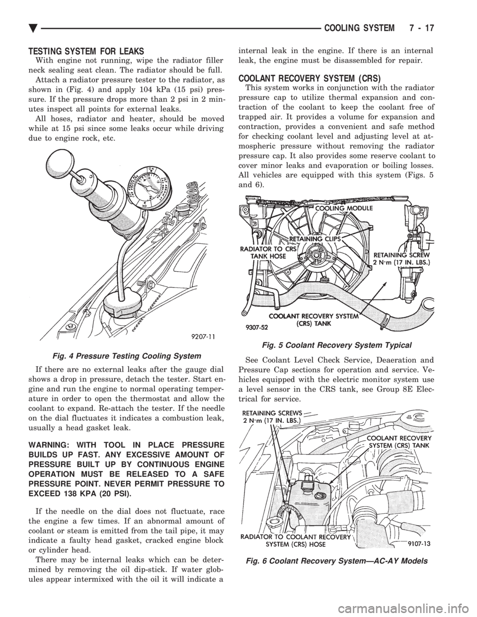
neck sealing seat clean. The radiator should be full. Attach a radiator pressure tester to the radiator, as
shown in (Fig. 4) and apply 104 kPa (15 psi) pres-
sure. If the pressure drops more than 2 psi in 2 min-
utes inspect all points for external leaks. All hoses, radiator and heater, should be moved
while at 15 psi since some leaks occur while driving
due to engine rock, etc.
If there are no external leaks after the gauge dial
shows a drop in pressure, detach the tester. Start en-
gine and run the engine to normal operating temper-
ature in order to open the thermostat and allow the
coolant to expand. Re-attach the tester. If the needle
on the dial fluctuates it indicates a combustion leak,
usually a head gasket leak.
WARNING: WITH TOOL IN PLACE PRESSURE
BUILDS UP FAST. ANY EXCESSIVE AMOUNT OF
PRESSURE BUILT UP BY CONTINUOUS ENGINE
OPERATION MUST BE RELEASED TO A SAFE
PRESSURE POINT. NEVER PERMIT PRESSURE TO
EXCEED 138 KPA (20 PSI).
If the needle on the dial does not fluctuate, race
the engine a few times. If an abnormal amount of
coolant or steam is emitted from the tail pipe, it may
indicate a faulty head gasket, cracked engine block
or cylinder head. There may be internal leaks which can be deter-
mined by removing the oil dip-stick. If water glob-
ules appear intermixed with the oil it will indicate a internal leak in the engine. If there is an internal
leak, the engine must be disassembled for repair.
COOLANT RECOVERY SYSTEM (CRS)
This system works in conjunction with the radiator
pressure cap to utilize thermal expansion and con-
traction of the coolant to keep the coolant free of
trapped air. It provides a volume for expansion and
contraction, provides a convenient and safe method
for checking coolant level and adjusting level at at-
mospheric pressure without removing the radiator
pressure cap. It also provides some reserve coolant to
cover minor leaks and evaporation or boiling losses.
All vehicles are equipped with this system (Figs. 5
and 6).
See Coolant Level Check Service, Deaeration and
Pressure Cap sections for operation and service. Ve-
hicles equipped with the electric monitor system use
a level sensor in the CRS tank, see Group 8E Elec-
trical for service.
Fig. 4 Pressure Testing Cooling System
Fig. 5 Coolant Recovery System Typical
Fig. 6 Coolant Recovery SystemÐAC-AY Models
Ä COOLING SYSTEM 7 - 17