1993 CHEVROLET DYNASTY change time
[x] Cancel search: change timePage 450 of 2438

to the thermostat housing (Fig. 20). The sensor pro-
vides an input voltage to the powertrain control mod-
ule (PCM). The sensor is a variable resistance
(thermistor) with a range of -40ÉF to 265ÉF. As cool-
ant temperature varies, the sensors resistance
changes, resulting in a different input voltage to the
PCM. The PCM contains different spark advance sched-
ules for cold and warm engine operation. The sched-
ules reduce engine emissions and improve
driveability. Because spark advance changes at dif-
ferent engine operating temperatures during warm-
up, all spark advance testing should be done with the
engine fully warmed. The PCM demands slightly richer air-fuel mixtures
and higher idle speeds until the engine reaches nor-
mal operating temperature. The coolant sensor input is also used for radiator
fan control.
MANIFOLD ABSOLUTE PRESSURE (MAP) SENSOR
The MAP sensor reacts to absolute pressure in the
intake manifold and provides an input voltage to the
powertrain control module (PCM). As engine load
changes, manifold pressure varies. The changes in
engine load causes the MAP sensors output voltage
to change. The change in MAP sensor output voltage
results in a different input voltage to the PCM. The input voltage level supplies the PCM with in-
formation relating to ambient barometric pressure
during engine start-up (cranking) and engine load
while its operating. The PCM uses this input along
with inputs from other sensors to adjust air-fuel mix-
ture. On 2.2L TBI, 2.5L TBI and 2.5L MPI (flexible fuel
AA-body) engines, the MAP sensor is mounted to the
dash panel (Fig. 21 or Fig. 22). On 3.0L engines, the
sensor is mounted to a bracket across from the dis-
tributor (Fig. 23). The sensor is connected to the
throttle body or intake manifold with a vacuum hose
and to the PCM electrically.
AUTO SHUTDOWN (ASD) RELAY AND FUEL PUMP
RELAY
The powertrain control module (PCM) operates the
auto shutdown (ASD) relay and fuel pump relay
through one ground path. The PCM operates the re-
lays by switching the ground path on and off. Both
relays turn on and off at the same time. The ASD relay connects battery voltage to the fuel
injector and ignition coil. The fuel pump relay con-
nects battery voltage to the fuel pump and oxygen
sensor heating element. The PCM turns the ground path off when the igni-
tion switch is in the Off position. Both relays are off.
When the ignition switch is in the On or Crank po-
sition, the PCM monitors the distributor pick-up sig-
Fig. 19 Coolant Temperature SensorÐ2.2L TBI, 2.5L TBI and 2.5L MPI Engines
Fig. 20 Coolant Temperature SensorÐ3.0L Engines
Fig. 21 MAP SensorÐ2.2L and 2.5L TBI Engines
8D - 8 IGNITION SYSTEMS Ä
Page 469 of 2438
mal wear can usually be cleaned, have the electrodes
filed and regapped, and then reinstalled. Some fuel refiners in several areas of the United
States have introduced a manganese additive (MMT)
for unleaded fuel. During combustion, fuel with MMT
may coat the entire tip of the spark plug with a rust
colored deposit. The rust color deposits can be misdi-
agnosed as being caused by coolant in the combustion
chamber. Spark plug performance is not affected by
MMT deposits.
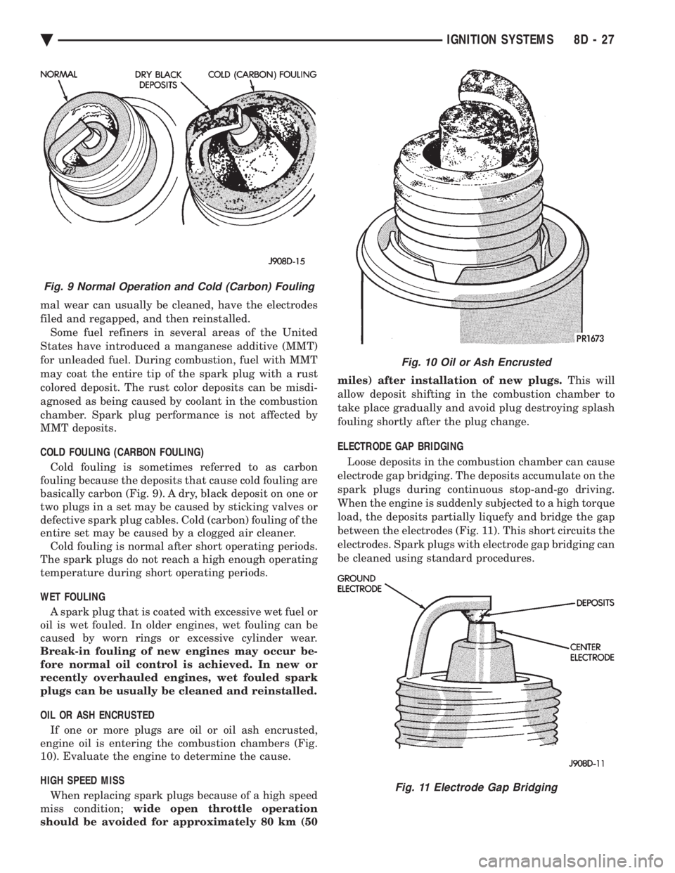
COLD FOULING (CARBON FOULING) Cold fouling is sometimes referred to as carbon
fouling because the deposits that cause cold fouling are
basically carbon (Fig. 9). A dry, black deposit on one or
two plugs in a set may be caused by sticking valves or
defective spark plug cables. Cold (carbon) fouling of the
entire set may be caused by a clogged air cleaner. Cold fouling is normal after short operating periods.
The spark plugs do not reach a high enough operating
temperature during short operating periods.
WET FOULING A spark plug that is coated with excessive wet fuel or
oil is wet fouled. In older engines, wet fouling can be
caused by worn rings or excessive cylinder wear.
Break-in fouling of new engines may occur be-
fore normal oil control is achieved. In new or
recently overhauled engines, wet fouled spark
plugs can be usually be cleaned and reinstalled.
OIL OR ASH ENCRUSTED If one or more plugs are oil or oil ash encrusted,
engine oil is entering the combustion chambers (Fig.
10). Evaluate the engine to determine the cause.
HIGH SPEED MISS When replacing spark plugs because of a high speed
miss condition; wide open throttle operation
should be avoided for approximately 80 km (50 miles) after installation of new plugs.
This will
allow deposit shifting in the combustion chamber to
take place gradually and avoid plug destroying splash
fouling shortly after the plug change.
ELECTRODE GAP BRIDGING
Loose deposits in the combustion chamber can cause
electrode gap bridging. The deposits accumulate on the
spark plugs during continuous stop-and-go driving.
When the engine is suddenly subjected to a high torque
load, the deposits partially liquefy and bridge the gap
between the electrodes (Fig. 11). This short circuits the
electrodes. Spark plugs with electrode gap bridging can
be cleaned using standard procedures.
Fig. 9 Normal Operation and Cold (Carbon) Fouling
Fig. 10 Oil or Ash Encrusted
Fig. 11 Electrode Gap Bridging
Ä IGNITION SYSTEMS 8D - 27
Page 474 of 2438

The coil's low primary resistance allows the PCM to
fully charge the coil for each firing.
COOLANT TEMPERATURE SENSOR
On 2.2L Turbo III engines, the coolant temperature
sensor is installed into the thermostat housing (Fig. 30).
On 3.3L and 3.8L engines, the coolant temperature sensor
is located next to the thermostat housing (Fig. 31).
The coolant temperature sensor provides an input
voltage to the powertrain control module (PCM). The
sensor is a variable resistance (thermistor) with a
range of -40ÉC to 130ÉC (-40ÉF to 265ÉF). As coolant
temperature varies, the sensor resistance changes,
resulting in a different input voltage to the PCM.
The PCM contains different spark advance schedules
for cold and warm engine operation. The schedules reduce
engine emission and improve driveability.
The PCM demands slightly richer air-fuel mixtures
and higher idle speeds until the engine reaches normal
operating temperature. The coolant sensor input is also used for cooling
fan control.
KNOCK SENSORÐTURBO III ENGINE
Turbo III engines use a knock sensor. The sensor gen-
erates a signal when spark detonation occurs in the
combustion chambers. The sensor is mounted on the in-
take manifold behind the PCV breather (Fig. 32). The
sensor provides input voltage used by the powertrain
control module (PCM) to modify spark advance and
boost schedules in order to eliminate detonation.
MANIFOLD ABSOLUTE PRESSURE (MAP) SENSOR
The MAP sensor reacts to absolute pressure in the
intake manifold and provides an input voltage to the
powertrain control module (PCM). As engine load
changes, manifold pressure varies. The changes in
engine load cause the MAP output voltage to change.
The change in MAP sensor output voltage results in
a different input voltage to the PCM.
The input voltage level supplies the PCM with infor-
mation relating to ambient barometric pressure during
engine start-up (cranking) and engine load while its op-
erating. The PCM uses this input along with inputs
from other sensors to adjust air-fuel mixture.
On Turbo III engines, the MAP sensor is mounted
to the front right fender (Fig. 33) On 3.3L and 3.8L
engines, the MAP sensor (Fig. 34) is mounted to the
side of the intake manifold, below the positive crank-
case ventilation (PCV) valve. The sensor is connected
to the PCM electrically.
AUTO SHUTDOWN (ASD) RELAY AND FUEL PUMP
RELAY
The powertrain control module (PCM) operates the
auto shutdown (ASD) relay and fuel pump relay
through one ground path. The PCM operates the re-
lays by switching the ground path on and off. Both
relays turn on and off at the same time.
Fig. 32 Knock SensorÐTurbo III Engine
Fig. 30 Coolant Temperature SensorÐTurbo III En- gines
Fig. 31 Coolant Temperature SensorÐ3.3L and 3.8LEngines
8D - 32 IGNITION SYSTEMS Ä
Page 605 of 2438

INOPERATIVE SYSTEM
If road test verifies an inoperative system with a
correct speedometer operation:
² Inspect fuse
² Check for loose electrical and vacuum connections
at the servo
² Check for correct position of the vacuum check
valve in the hose from servo to vacuum source. The
word VAC on the valve must point toward the vac-
uum source.
² Inspection should also be made to verify that both
ends of the vehicle speed control cable are securely
attached. If either end is loose, the vehicle speed con-
trol will be inoperative.
CHECKING FOR FAULT CODE
(1) When trying to verify a vehicle speed control
electronic malfunction: (a) Connect a DRB II if available.
(b) Plug DRB II into the diagnostic connector in
the engine compartment. (c) Check that either a Fault Code 34 or Fault
Code 15 is indicated. (d) An inoperative vehicle speed control may still
occur without either fault code being indicated. (e) With key inserted in ignition switch, cycle
switch to ON position three times. On third cycle,
leave switch in ON position. (f) After switch has been cycled three times, ob-
serve CHECK ENGINE indicator on instrument
cluster. If a Fault Code is present, indicator will
flash (blink) in a series which will show which
Fault Code is the problem. EXAMPLE: A series of
three flashes in rapid succession, a slight pause,
then four flashes in rapid succession would indicate
Fault Code 34.
(2) If no Fault Code appears, or Fault Code 34 is
observed, refer to:
² The Servo Electrical Test.
² The Powertrain Control Module Electrical Test.
(3) If a fault code 15 is observed, test vehicle speed
sensor. For testing vehicle speed sensor and related compo-
nents refer to the Powertrain Diagnostics Test Proce-
dure Manual. (4) Correct any problems found when performing
these tests and recheck for Fault Code if changes
were made. (5) If no problems were found above, replace pow-
ertrain control module.
VEHICLE SPEED CONTROL ELECTRICAL TESTS
WARNING: IF REMOVAL OF AIR BAG MODULE IS
NECESSARY, REFER TO GROUP 8M, RESTRAINT
SYSTEMS.
Fig. 6 Vehicle Speed ControlÐAC & AY Bodies with 2.5L
Ä VEHICLE SPEED CONTROL 8H - 3
Page 621 of 2438
WINDSHIELD WIPER AND WASHER SYSTEMS
CONTENTS
page page
GENERAL WIPER INFORMATION ........... 1
INTERMITTENT WINDSHIELD WIPER MOTOR AND SWITCH SERVICE PROCEDURES .... 12
WINDSHIELD WASHERS ................. 17 WINDSHIELD WIPER BLADE AND ARM SERVICE
PROCEDURES ......................... 1
WINDSHIELD WIPER MOTOR AND LINKAGE ASSEMBLY SERVICE PROCEDURES ....... 3
GENERAL WIPER INFORMATION
WARNING: ON VEHICLES EQUIPPED WITH AIR-
BAG, SEE GROUP 8M, RESTRAINT SYSTEMS FOR
STEERING WHEEL OR COLUMN REMOVAL PROCE-
DURES.
The windshield wipers can be operated with the
windshield wiper switch only when the ignition
switch is in the ACCESSORY or IGNITION position.
A fuse, located in the fuse block, protects the cir-
cuitry of the wiper system and the vehicle. The wiper motor has permanent magnet fields. The speeds are determined by current flow to the appro-
priate set of brushes. The intermittent wipe system, in addition to low
and high speed, has a delay mode. The delay mode
has a range of 2 to 15 seconds. This is accomplished
by a variable resistor in the wiper switch and is con-
trolled electrically by a relay. The wiper system completes the wipe cycle when
the switch is turned OFF. The blades park in the
lowest portion of the wipe pattern.
WINDSHIELD WIPER BLADE AND ARM SERVICE PROCEDURES
WIPER BLADES
Wiper blades, exposed to the weather for a long pe-
riod of time, tend to lose their wiping effectiveness.
Periodic cleaning of the wiper blade is suggested to
remove the accumulation of salt and road film. The
wiper blades, arms, and windshield should be cleaned
with a sponge or cloth and a mild detergent or nona-
brasive cleaner. If the blades continue to streak or
smear, they should be replaced.
WIPER BLADE ELEMENT CHANGE
(1) Turn wiper switch ON, position blades to a con-
venient place by turning the ignition switch ON and
OFF. (2) Lift wiper arm to raise blade off glass.
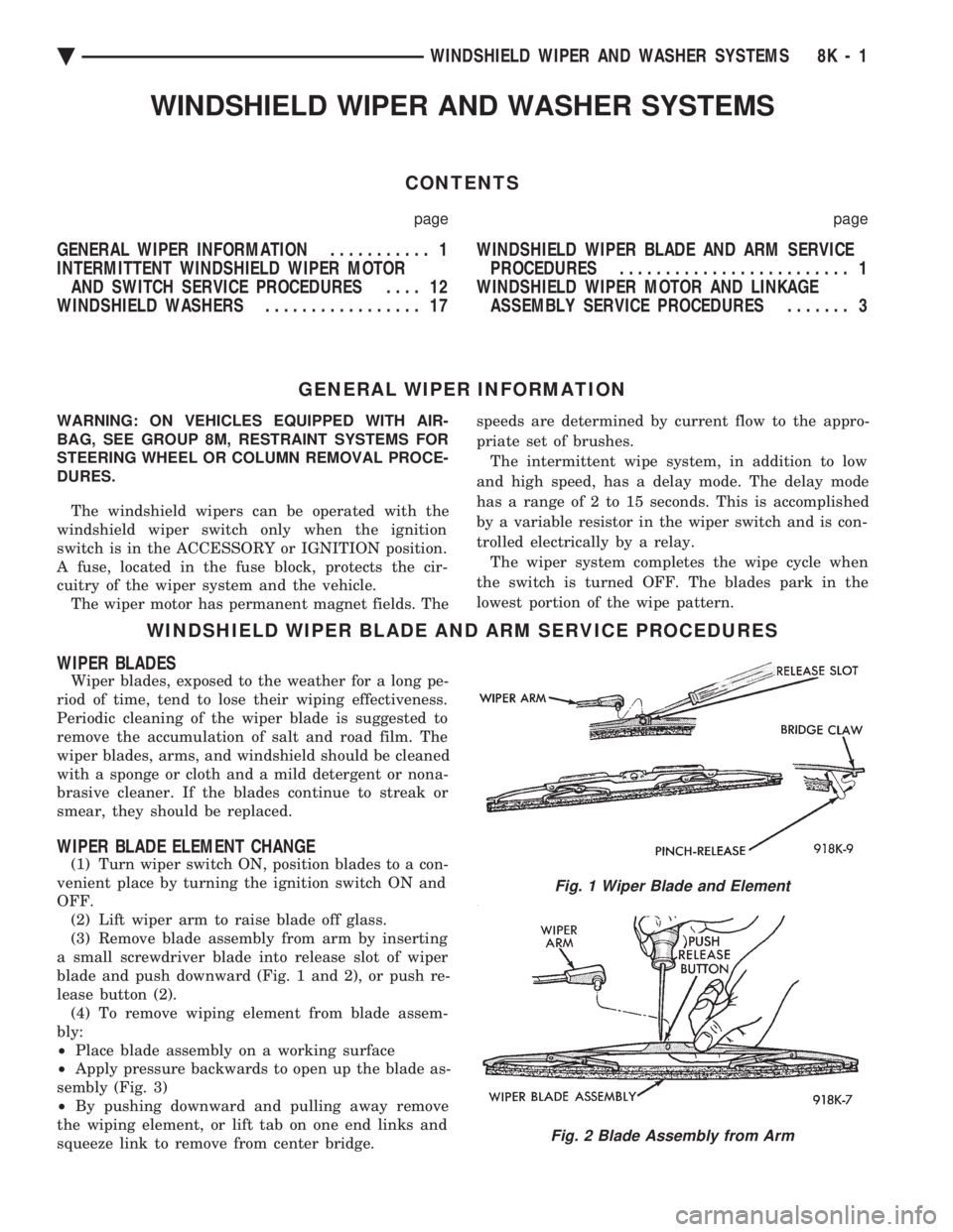
(3) Remove blade assembly from arm by inserting
a small screwdriver blade into release slot of wiper
blade and push downward (Fig. 1 and 2), or push re-
lease button (2). (4) To remove wiping element from blade assem-
bly:
² Place blade assembly on a working surface
² Apply pressure backwards to open up the blade as-
sembly (Fig. 3)
² By pushing downward and pulling away remove
the wiping element, or lift tab on one end links and
squeeze link to remove from center bridge.
Fig. 1 Wiper Blade and Element
Fig. 2 Blade Assembly from Arm
Ä WINDSHIELD WIPER AND WASHER SYSTEMS 8K - 1
Page 683 of 2438

RESTRAINT SYSTEMS
CONTENTS
page page
AIR BAG MODULE ....................... 4
AIR BAG SERVICE AND TEST PROCEDURES . 1
AIR BAG SYSTEM CHECK ................. 3
AIR BAG SYSTEM DIAGNOSTIC MODULE (ASDM) .............................. 5
CLOCKSPRING .......................... 6
CLOCKSPRING CENTERING PROCEDURE .... 6 GENERAL INFORMATION
.................. 1
LEFT FRONT IMPACT SENSOR ............. 4
RIGHT FRONT IMPACT SENSOR ........... 5
SCHEDULED MAINTENANCE INSPECTION .... 3
STEERING COLUMN SWITCHES ............ 7
STEERING WHEEL ....................... 7
AIR BAG SERVICE AND TEST PROCEDURES
WARNING: THIS SYSTEM IS A SENSITIVE, COM-
PLEX ELECTRO-MECHANICAL UNIT. BEFORE AT-
TEMPTING TO DIAGNOSE, REMOVE OR INSTALL
THE AIR BAG SYSTEM COMPONENTS, YOU MUST
FIRST DISCONNECT AND ISOLATE THE NEGATIVE
(GROUND) BATTERY CABLE. FAILURE TO DO SO
COULD RESULT IN ACCIDENTAL DEPLOYMENT
AND POSSIBLE PERSONAL INJURY. WHEN AN UNDEPLOYED AIR BAG ASSEMBLY
IS TO BE REMOVED FROM THE STEERING
WHEEL, DISCONNECT BATTERY GROUND CA-
BLE AND ISOLATE. ALLOW SYSTEM CAPACI-
TOR TO DISCHARGE FOR TWO MINUTES THEN
BEGIN AIR BAG SYSTEM COMPONENT RE-
MOVAL. Vehicles equipped with a Air Bag System must be
inspected every three years or 30,000 miles / 48,000
Km. To inspect system use Passive Restraint System
Diagnostic Procedures Manual. If the Air Bag Module Assembly is defective and
non-deployed, refer to Chrysler Motors current re-
turn list for proper handling procedures.
WARNING: REPLACE AIR BAG SYSTEM COMPO-
NENTS WITH CHRYSLER MOPAR TSPECIFIED RE-
PLACEMENT PARTS. SUBSTITUTE PARTS MAY
VISUALLY APPEAR INTERCHANGEABLE, BUT IN-
TERNAL DIFFERENCES MAY RESULT IN INFERIOR
OCCUPANT PROTECTION.
THE FASTENERS, SCREWS, AND BOLTS, ORIG-
INALLY USED FOR THE AIR BAG COMPO-
NENTS, HAVE SPECIAL COATINGS AND ARE
SPECIFICALLY DESIGNED FOR THE AIR BAG
SYSTEM. THEY MUST NEVER BE REPLACED
WITH ANY SUBSTITUTES. ANYTIME A NEW
FASTENER IS NEEDED, REPLACE WITH THE CORRECT FASTENERS PROVIDED IN THE SER-
VICE PACKAGE OR FASTENERS LISTED IN THE
PARTS BOOKS.
GENERAL INFORMATION
AIR BAG MODULE
The air bag module is the most visible part of the
system (Fig 1). It contains the air bag cushion and
its supporting components. The air bag module con-
tains a housing to which the cushion and inflator are
attached and sealed.
The inflator assembly is mounted to the back of the
module housing. When supplied with the proper elec-
trical signal the inflator assembly will produce a gas
and discharges it directly into the cushion. A protec-
tive cover is fitted to the front of the air bag module
and forms a decorative cover in the center of the
steering wheel. The air bag module is mounted di-
rectly to the steering wheel.
Fig. 1 Air Bag Passive Restraint System
Ä RESTRAINT SYSTEMS 8M - 1
Page 692 of 2438

(6) Steps (3, 4 or 5) above will confirm system op-
eration. Indicator light illumination means that
there is power available at the output of the relay
only, and does not necessarily verify system opera-
tion. (7) If turning the switch ON produced no distinct
current draw on the ammeter the problem should be
isolated in the following manner: (a) Confirm the ignition switch is ON.
(b) Ensure that the heated rear glass feed wire is
connected to the terminal or pigtail and that the
ground wire is in fact grounded. (c) Ensure that the fusible link and control cir-
cuit fuse is operational and all electrical connec-
tions are secure.
(8) When the above steps have been completed and
the system is still inoperative, one or more of the fol-
lowing is defective: (a) Control switch/timer relay module.
(b) All rear window grid lines would have to be
broken or one of the feed wires are not connected
for the system to be inoperative.
(9) If turning the switch ON produces severe volt-
meter deflection, the circuit should be closely
checked for a shorting condition. (10) If the system operation has been verified but
indicator lamp does not light, replace the switch. (11) For detailed wiring information, refer to group
8W, Wiring Diagrams.
GRID TEST
The horizontal grid lines and vertical bus bar lines
printed and fired on inside surface of rear window
glass (Fig. 2) comprise an electrical parallel circuit.
The electrically conductive lines are composed of a
silver-ceramic material which when fired on glass be-
comes bonded to the glass and is highly resistant to
abrasion. It is possible, however, that a break may
occur in an individual grid line resulting in no cur-
rent flow through the line. To detect breaks in grid
lines the following procedure is required: (1) Turn ignition ON and turn control switch to
ON. The indicator light should come on. (2) Using a DC voltmeter with 0-15 volt range,
contact terminal B with negative lead of voltmeter.
With positive lead of voltmeter, contact terminal A
(Fig. 2). The voltmeter should read 10-14 volts. A
lower voltage reading indicates a poor ground con-
nection. (3) With negative lead of voltmeter, contact a good
body ground point. The voltage reading should not
change. (4) Connect negative lead of voltmeter to terminal
B and touch each grid line at Mid-Point with Posi-
tive lead. A reading of approximately 6 volts indi-
cates a line is good. A reading of 0 volts indicates a
break in line between Mid-Point C and terminal A.
A reading of 10-14 volts indicates a break between Mid-Point C and terminal B. Move toward break and
voltage will change as soon as break is crossed (Figs.
2 and 3).
CONTROL SWITCH/TIMER RELAY MODULE TEST
Control switch/timer relay module may be tested
in-vehicle or bench tested. In vehicle testing is ac-
complished in the following manner: (1) Remove the switch, relay assembly from the in-
strument panel or console, see Group 8E, Instrument
Panel and leave the switch connector plugged in. (2) Turn ignition ON.
(3) Using a DC voltmeter, with 0-15 range, check
voltage at terminals B, I and L. (Figs. 3 and 4). Ter-
minals B and I should confirm a voltage of 10 to 14
volts to ground when the ON switch is pressed. Ter-
minal L should confirm voltage to ground. When ter-
minals B and I show no voltage, trace circuit
upstream of switch/relay module for problem (wiring
cut, fusible link or circuit breaker inoperative, bulk-
head connector not operative, etc.) If terminal L in-
dicates voltage, place switch in Off position. If
voltage at L is still indicated or indicator lamp re-
mains on, the switch/relay module should be re-
placed. (4) If the relay checks out to this point, momen-
tarily operate switch to ON position. The indicator
lamp should come on and remain on for approxi-
mately 10 minutes. Terminal L should confirm volt-
age. If the indicator lamp fails to light or voltage at
terminal L is not confirmed the switch/relay module
should be replaced.
Fig. 3 Systems Electrical Circuit
8N - 2 REAR WINDOW DEFOGGER Ä
Page 744 of 2438
(2) The headlamps and parking lamps should turn
ON for about five seconds.
² AUTO MIRROR LED
² DARK LED
² AUTO LAMP LED
² The LED indicators blink for about 5 seconds.
² If the three indicators continue to blink consider-
ably longer than 5 seconds, then the mirror assembly
is defective. (3) The mirror should change to dim state.(a) Place shift selector in reverse (R), with igni-
tion switch ON:
² AUTO MIRROR LED indicator ON
² DARK LED indicator flashing
² Lasting about 15 seconds
(b) The mirror should slowly change to bright
state. (c) If the ignition is not turned OFF within the
15 second time period, the mirror will reset to its
previous setting.
The previous conditions are OK, the mirror is op-
erating properly. If not OK, continue with voltage tests below.
VOLTAGE TEST
To test for voltage insert voltmeter probe into wire
end of connector to contact terminal. Pin 1 ignition voltage (a) Ignition switch OFF, zero volts.
(b) Ignition switch ON, battery voltage.
Pin 2 battery voltage (a) Battery voltage at all times.
(b) No voltage, check 15 amp. fuse.
Pin 3 Ground (a) Continuity to ground.
(b) No voltage
Pin 4 Reverse over-ride (a) Ignition OFF, zero voltage.
(b) Ignition ON shift selector in Reverse (R), bat-
tery voltage. (c) Ignition ON shift selector in any position
other than Reverse (R), zero voltage.
Pin 5 Headlamp relay (a) Battery voltage at all times from headlamp
relay. (b) No battery voltage, test headlamp relay.
Pin 6 Park lamp relay (a) Ignition switch ON, battery voltage feed from
park lamp relay. (b) Ignition switch OFF, zero voltage.
(c) Ignition ON, No battery voltage test park
lamp relay.
If Voltage Test are OK, replace mirror assembly.
If not OK, refer to Wiring Diagrams manual.
8T - 8 POWER MIRRORS Ä