1993 CHEVROLET DYNASTY wheel bolt torque
[x] Cancel search: wheel bolt torquePage 116 of 2438
(3) Install washer and nut. Tighten nut to 27-34
N Im (240-300 in. lbs.) torque while rotating brake
drum. Then back off nut to completely release pre-
load. Finger tighten nut. (4) Position nut lock with one pair of slots in-line
with cotter pin hole. Install cotter pin. Clean and in-
stall grease cap. DISC BRAKE ASSEMBLY
(1) Position caliper support and spindle to axle. In-
stall the 4 spindle mounting bolts finger tight. Then
torque the 4 spindle mounting bolts to 75 N Im (55 ft.
lbs.) torque. (2) Install hub and bearings. (3) Install washer and nut. Tighten to 27-34 N
Im
(240-300 in. lbs.) torque while rotating hub. Then
back off nut to completely release preload. Finger
tighten nut. (4) Position nut lock with one pair of slots in-line
with cotter pin hole. Install cotter pin. Clean and in-
stall grease cap. (5) Install braking disc and adapter. Install caliper
assembly (see Rear Disc Brake) in Brakes Section,
Group 5. (6) Attach brake hose and parking brake cable to
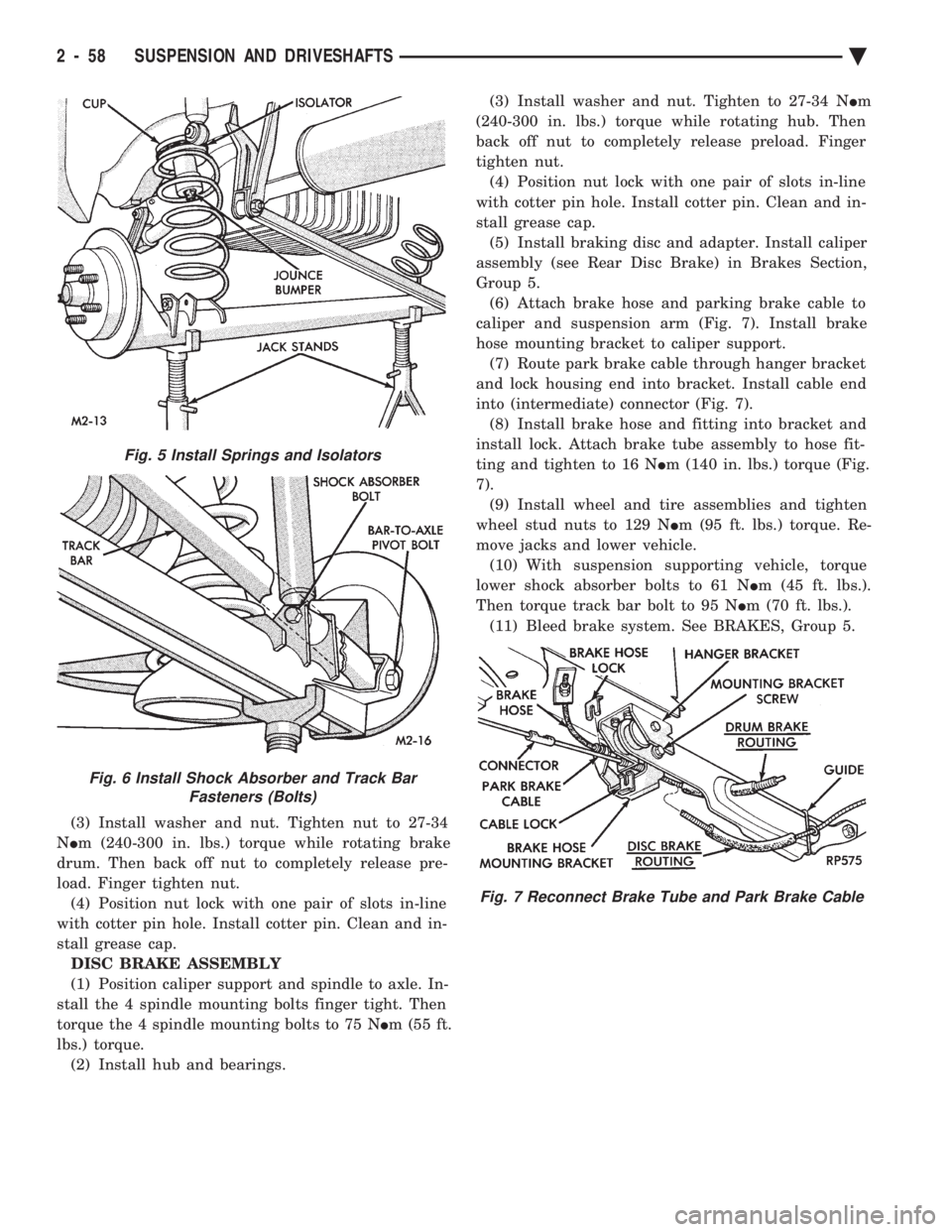
caliper and suspension arm (Fig. 7). Install brake
hose mounting bracket to caliper support. (7) Route park brake cable through hanger bracket
and lock housing end into bracket. Install cable end
into (intermediate) connector (Fig. 7). (8) Install brake hose and fitting into bracket and
install lock. Attach brake tube assembly to hose fit-
ting and tighten to 16 N Im (140 in. lbs.) torque (Fig.
7). (9) Install wheel and tire assemblies and tighten
wheel stud nuts to 129 N Im (95 ft. lbs.) torque. Re-
move jacks and lower vehicle. (10) With suspension supporting vehicle, torque
lower shock absorber bolts to 61 N Im (45 ft. lbs.).
Then torque track bar bolt to 95 N Im (70 ft. lbs.).
(11) Bleed brake system. See BRAKES, Group 5.
Fig. 5 Install Springs and Isolators
Fig. 6 Install Shock Absorber and Track Bar Fasteners (Bolts)
Fig. 7 Reconnect Brake Tube and Park Brake Cable
2 - 58 SUSPENSION AND DRIVESHAFTS Ä
Page 147 of 2438
REAR (STUB) AXLE ALIGNMENT ALL MODELS INDEX
page page
General Information ....................... 89 Rear Wheel Alignment..................... 89
GENERAL INFORMATION
Because front wheel drive vehicles are equipped with
rear suspension incorporating stub axles (or wheel
spindles). It is possible to align both the camber and toe
of the rear wheels.
REAR WHEEL ALIGNMENT
Alignment adjustment if required. Is made by adding
0.010 inch shims (from the service package kit) be-
tween the spindle mounting surface and axle mounting
plate. Each shim equals wheel change by .3É as shown
(for all car lines) in (Figs. 3 to 6). If rear wheel alignment is required, place vehicle on
alignment rack and check alignment specifications.
When recording rear toe-in (vehicle backed onto
alignment rack) REMEMBER to reverse sign
convention; a total toe-in on direct reading
charts is actually toe-out while driving. Maintain
rear alignment within Chrysler Motors recommenda-
tions, found in Specifications.
INSTALLATION OF REAR ALIGNMENT SHIMS
(1) Block front tires so vehicle will not move.
(2) Release parking brake.
(3) Hoist vehicle so that rear suspension is in full
rebound and tires are off the ground. See Hoisting in
Lubrication and Maintenance, Group 0. (4) Remove wheel and tire assembly.
(5) Pry off grease cap.
(6) Remove cotter pin and castle lock.
(7) Remove adjusting nut.
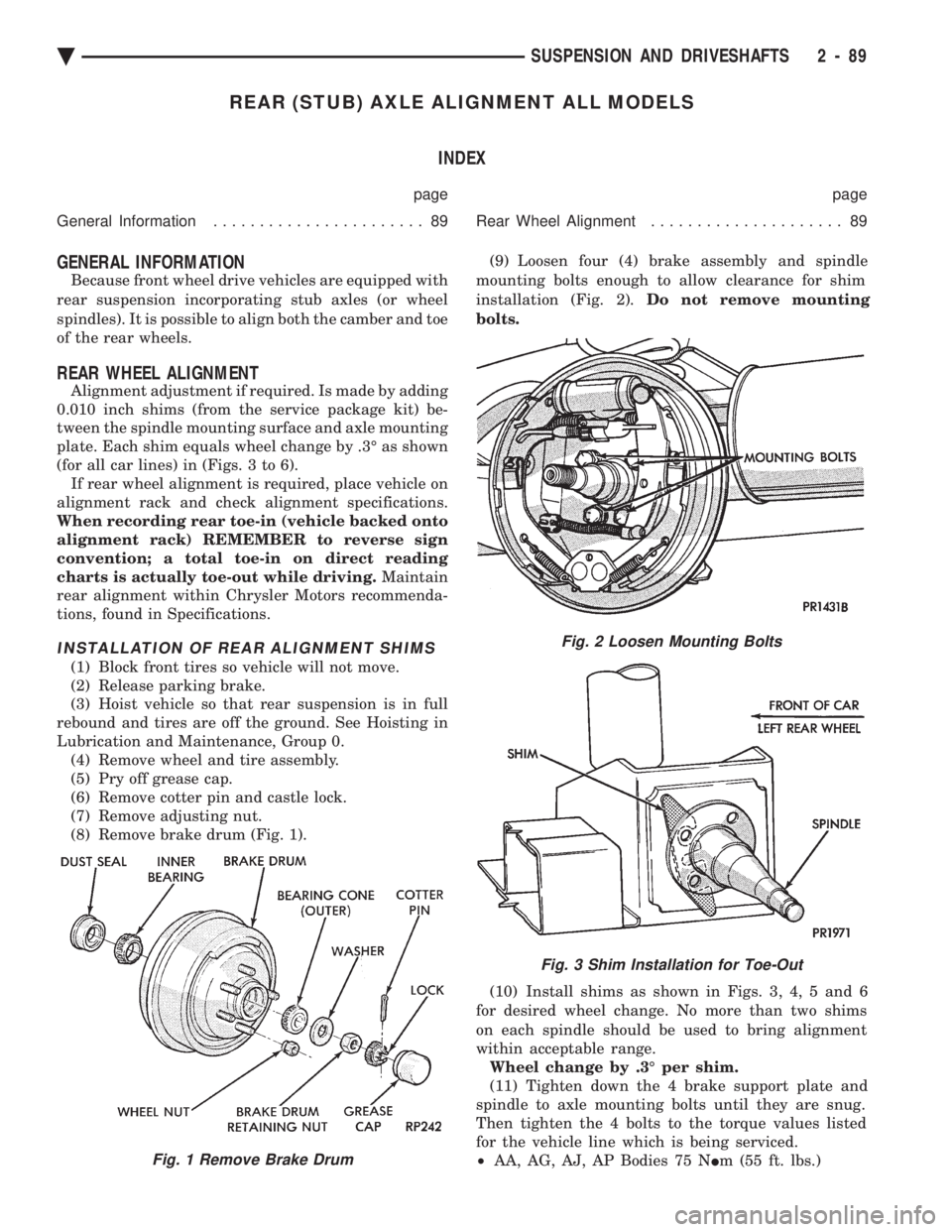
(8) Remove brake drum (Fig. 1). (9) Loosen four (4) brake assembly and spindle
mounting bolts enough to allow clearance for shim
installation (Fig. 2). Do not remove mounting
bolts.
(10) Install shims as shown in Figs. 3, 4, 5 and 6
for desired wheel change. No more than two shims
on each spindle should be used to bring alignment
within acceptable range. Wheel change by .3É per shim.
(11) Tighten down the 4 brake support plate and
spindle to axle mounting bolts until they are snug.
Then tighten the 4 bolts to the torque values listed
for the vehicle line which is being serviced.
² AA, AG, AJ, AP Bodies 75 N Im (55 ft. lbs.)
Fig. 2 Loosen Mounting Bolts
Fig. 3 Shim Installation for Toe-Out
Fig. 1 Remove Brake Drum
Ä SUSPENSION AND DRIVESHAFTS 2 - 89
Page 161 of 2438
BRAKE HOSE AND TUBING
INSPECTION OF BRAKE HOSE AND TUBING
Flexible rubber hose is used at both front brakes and
at the rear axle. Inspection of brake hoses should be
performed whenever the brake system is serviced and
every 7,500 miles or 12 months, whichever comes first
(every engine oil change). Inspect hydraulic brake
hoses for severe surface cracking, scuffing, or worn
spots. Should the fabric casing of the rubber hose be
exposed due to cracks or abrasions in the rubber hose
cover, the hose should be replaced immediately. Even-
tual deterioration of the hose can take place with
possible burst failure. Faulty installation can cause
twisting and wheel, tire or chassis interference. The steel brake tubing should be inspected periodi-
cally for evidence of physical damage or contact with
moving or hot components.
INSTALLATION OF BRAKE HOSE
Always use factory recommended brake hose to en-
sure quality, correct length and superior fatigue life.
Care should be taken to make sure that the tube and
hose mating surfaces are clean and free from nicks and
burrs. Front right and left side hoses are not
interchangeable. Connections should be correct and properly made.
Use new copper seal washers on all connections using
Banjo Bolts and tighten all fittings to their specified
torques. The flexible front hydraulic brake hose should al-
ways be installed on the vehicle by first attaching the
Banjo connector to the caliper assembly. Then bolt the
intermediate hose bracket to the strut assembly allow-
ing the bracket to position the hose to prevent twisting.
Attach the hose to the body bracket and steel brake
tubing. Tighten all fittings to specified torque. The
body bracket and hose end are keyed so that they will
only fit one way. Install rear brake hoses first to the trailing arm
tubes and then to the floor pan tubes. Minimize hose
twisting. Vehicles equipped with rear disc brakes have
brake hoses attached to the caliper on each side. The
brake hose should be first attached by the Banjo bolt to
the caliper and then secured to the hose bracket with
the retaining clip. The attach the steel brake tubing to
the hose fitting.
REPAIR AND INSTALLATION OF BRAKE TUB- ING
Only double wall 4.75mm (3/16 in.) steel tubing
should be used for replacement. Care should be taken
when replacing brake tubing, to be sure the proper
bending and flaring tools and procedures are used, to
avoid kinking. Do not route the tubes against sharp edges, moving components or into hot areas. All
tubes should be properly attached with recommended
retaining clips.
TYPES OF TUBING FLARES
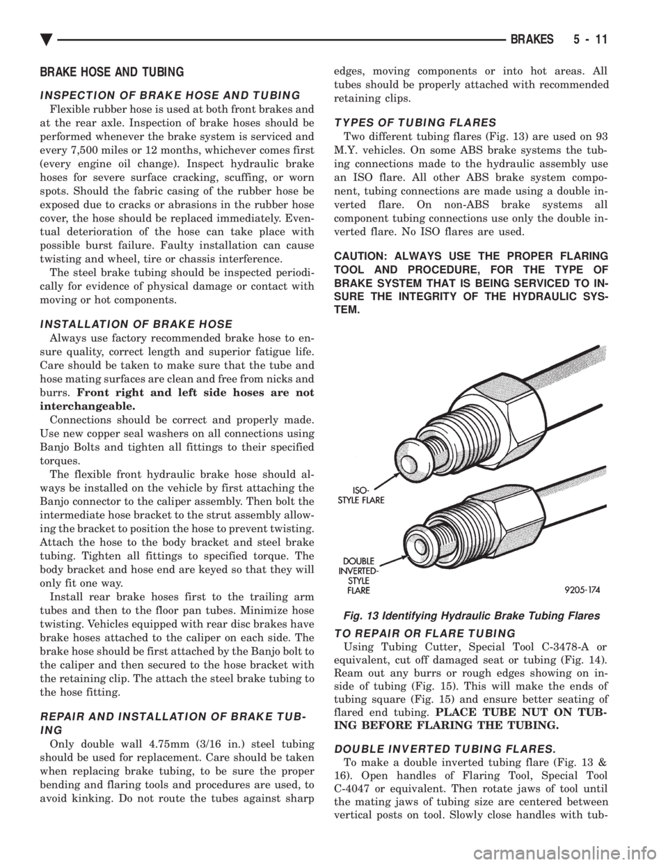
Two different tubing flares (Fig. 13) are used on 93
M.Y. vehicles. On some ABS brake systems the tub-
ing connections made to the hydraulic assembly use
an ISO flare. All other ABS brake system compo-
nent, tubing connections are made using a double in-
verted flare. On non-ABS brake systems all
component tubing connections use only the double in-
verted flare. No ISO flares are used.
CAUTION: ALWAYS USE THE PROPER FLARING
TOOL AND PROCEDURE, FOR THE TYPE OF
BRAKE SYSTEM THAT IS BEING SERVICED TO IN-
SURE THE INTEGRITY OF THE HYDRAULIC SYS-
TEM.
TO REPAIR OR FLARE TUBING
Using Tubing Cutter, Special Tool C-3478-A or
equivalent, cut off damaged seat or tubing (Fig. 14).
Ream out any burrs or rough edges showing on in-
side of tubing (Fig. 15). This will make the ends of
tubing square (Fig. 15) and ensure better seating of
flared end tubing. PLACE TUBE NUT ON TUB-
ING BEFORE FLARING THE TUBING.
DOUBLE INVERTED TUBING FLARES.
To make a double inverted tubing flare (Fig. 13 &
16). Open handles of Flaring Tool, Special Tool
C-4047 or equivalent. Then rotate jaws of tool until
the mating jaws of tubing size are centered between
vertical posts on tool. Slowly close handles with tub-
Fig. 13 Identifying Hydraulic Brake Tubing Flares
Ä BRAKES 5 - 11
Page 175 of 2438
BRAKE SUPPORT ASSEMBLY
REMOVAL
Back off parking brake adjusting nut to provide
slack in cable. With wheel and brake drum removed, disconnect
hydraulic tube from wheel cylinder.Disconnect park-
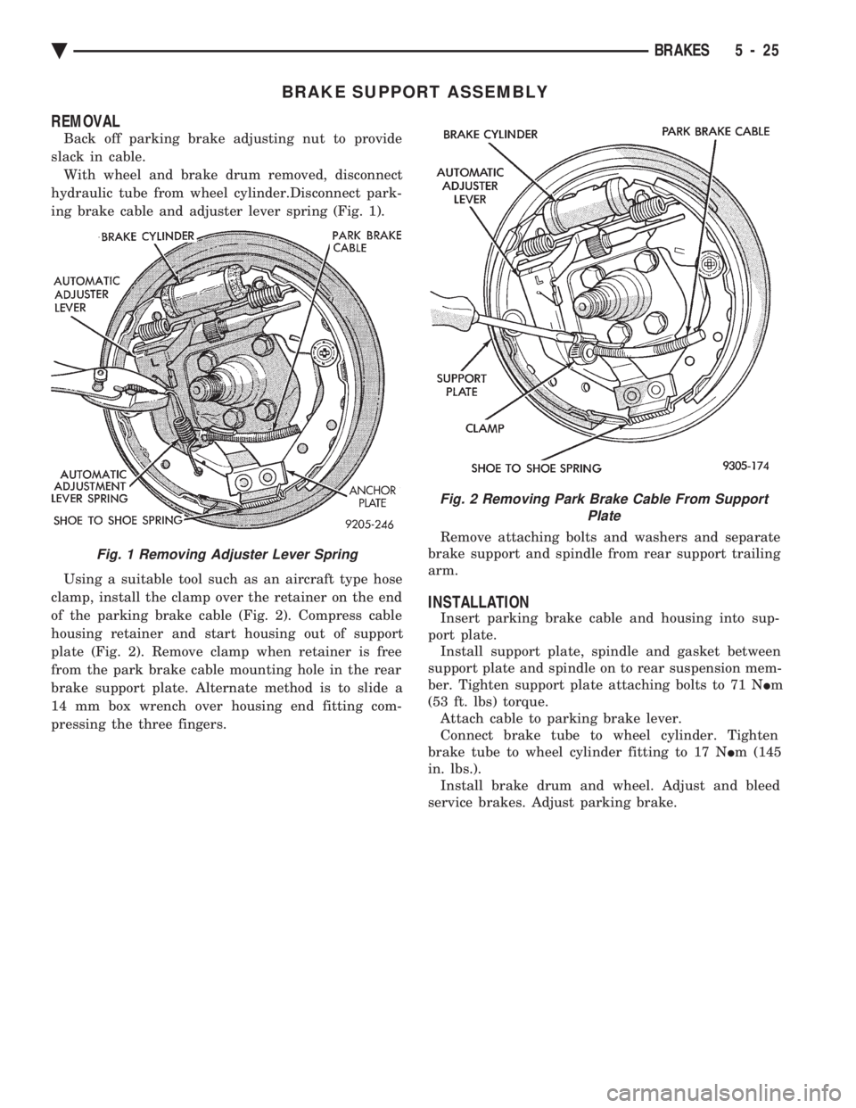
ing brake cable and adjuster lever spring (Fig. 1).
Using a suitable tool such as an aircraft type hose
clamp, install the clamp over the retainer on the end
of the parking brake cable (Fig. 2). Compress cable
housing retainer and start housing out of support
plate (Fig. 2). Remove clamp when retainer is free
from the park brake cable mounting hole in the rear
brake support plate. Alternate method is to slide a
14 mm box wrench over housing end fitting com-
pressing the three fingers. Remove attaching bolts and washers and separate
brake support and spindle from rear support trailing
arm.
INSTALLATION
Insert parking brake cable and housing into sup-
port plate. Install support plate, spindle and gasket between
support plate and spindle on to rear suspension mem-
ber. Tighten support plate attaching bolts to 71 N Im
(53 ft. lbs) torque. Attach cable to parking brake lever.
Connect brake tube to wheel cylinder. Tighten
brake tube to wheel cylinder fitting to 17 N Im (145
in. lbs.). Install brake drum and wheel. Adjust and bleed
service brakes. Adjust parking brake.
Fig. 1 Removing Adjuster Lever Spring
Fig. 2 Removing Park Brake Cable From Support Plate
Ä BRAKES 5 - 25
Page 187 of 2438
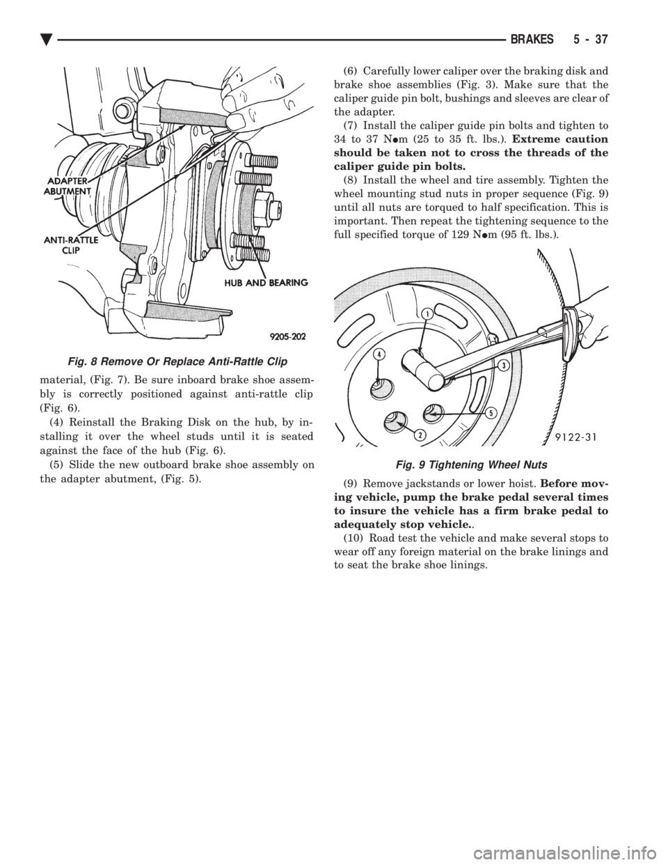
material, (Fig. 7). Be sure inboard brake shoe assem-
bly is correctly positioned against anti-rattle clip
(Fig. 6). (4) Reinstall the Braking Disk on the hub, by in-
stalling it over the wheel studs until it is seated
against the face of the hub (Fig. 6). (5) Slide the new outboard brake shoe assembly on
the adapter abutment, (Fig. 5). (6) Carefully lower caliper over the braking disk and
brake shoe assemblies (Fig. 3). Make sure that the
caliper guide pin bolt, bushings and sleeves are clear of
the adapter. (7) Install the caliper guide pin bolts and tighten to
34 to 37 N Im (25 to 35 ft. lbs.). Extreme caution
should be taken not to cross the threads of the
caliper guide pin bolts. (8) Install the wheel and tire assembly. Tighten the
wheel mounting stud nuts in proper sequence (Fig. 9)
until all nuts are torqued to half specification. This is
important. Then repeat the tightening sequence to the
full specified torque of 129 N Im (95 ft. lbs.).
(9) Remove jackstands or lower hoist. Before mov-
ing vehicle, pump the brake pedal several times
to insure the vehicle has a firm brake pedal to
adequately stop vehicle. .
(10) Road test the vehicle and make several stops to
wear off any foreign material on the brake linings and
to seat the brake shoe linings.
Fig. 8 Remove Or Replace Anti-Rattle Clip
Fig. 9 Tightening Wheel Nuts
Ä BRAKES 5 - 37
Page 190 of 2438
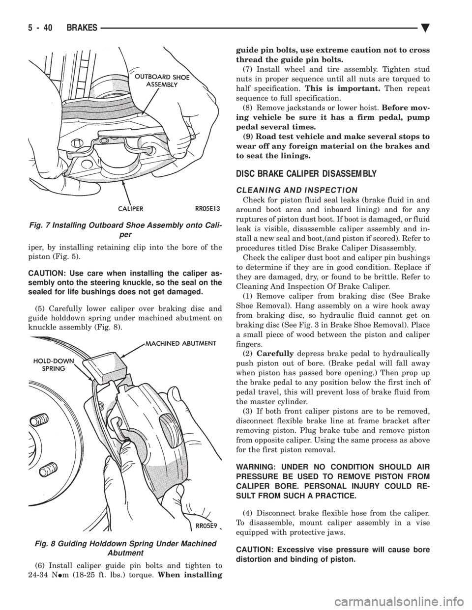
iper, by installing retaining clip into the bore of the
piston (Fig. 5).
CAUTION: Use care when installing the caliper as-
sembly onto the steering knuckle, so the seal on the
sealed for life bushings does not get damaged.
(5) Carefully lower caliper over braking disc and
guide holddown spring under machined abutment on
knuckle assembly (Fig. 8).
(6) Install caliper guide pin bolts and tighten to
24-34 N Im (18-25 ft. lbs.) torque. When installing guide pin bolts, use extreme caution not to cross
thread the guide pin bolts.
(7) Install wheel and tire assembly. Tighten stud
nuts in proper sequence until all nuts are torqued to
half specification. This is important. Then repeat
sequence to full specification. (8) Remove jackstands or lower hoist. Before mov-
ing vehicle be sure it has a firm pedal, pump
pedal several times. (9) Road test vehicle and make several stops to
wear off any foreign material on the brakes and
to seat the linings.
DISC BRAKE CALIPER DISASSEMBLY
CLEANING AND INSPECTION
Check for piston fluid seal leaks (brake fluid in and
around boot area and inboard lining) and for any
ruptures of piston dust boot. If boot is damaged, or fluid
leak is visible, disassemble caliper assembly and in-
stall a new seal and boot,(and piston if scored). Refer to
procedures titled Disc Brake Caliper Disassembly. Check the caliper dust boot and caliper pin bushings
to determine if they are in good condition. Replace if
they are damaged, dry, or found to be brittle. Refer to
Cleaning And Inspection Of Brake Caliper. (1) Remove caliper from braking disc (See Brake
Shoe Removal). Hang assembly on a wire hook away
from braking disc, so hydraulic fluid cannot get on
braking disc (See Fig. 3 in Brake Shoe Removal). Place
a small piece of wood between the piston and caliper
fingers. (2) Carefully depress brake pedal to hydraulically
push piston out of bore. (Brake pedal will fall away
when piston has passed bore opening.) Then prop up
the brake pedal to any position below the first inch of
pedal travel, this will prevent loss of brake fluid from
the master cylinder. (3) If both front caliper pistons are to be removed,
disconnect flexible brake line at frame bracket after
removing piston. Plug brake tube and remove piston
from opposite caliper. Using the same process as above
for the first piston removal.
WARNING: UNDER NO CONDITION SHOULD AIR
PRESSURE BE USED TO REMOVE PISTON FROM
CALIPER BORE. PERSONAL INJURY COULD RE-
SULT FROM SUCH A PRACTICE.
(4) Disconnect brake flexible hose from the caliper.
To disassemble, mount caliper assembly in a vise
equipped with protective jaws.
CAUTION: Excessive vise pressure will cause bore
distortion and binding of piston.
Fig. 7 Installing Outboard Shoe Assembly onto Cali- per
Fig. 8 Guiding Holddown Spring Under MachinedAbutment
5 - 40 BRAKES Ä
Page 197 of 2438
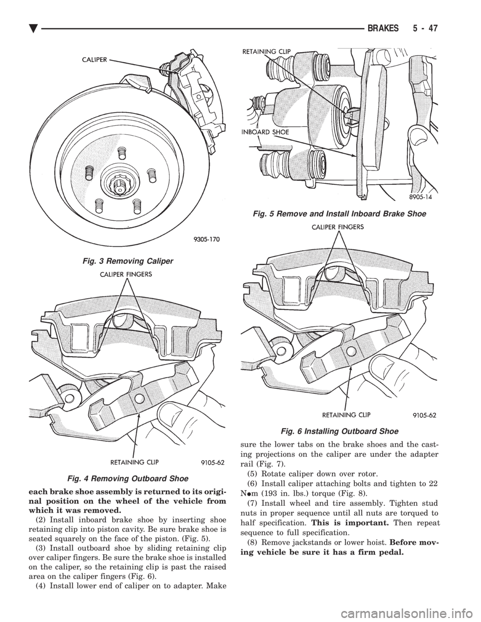
each brake shoe assembly is returned to its origi-
nal position on the wheel of the vehicle from
which it was removed. (2) Install inboard brake shoe by inserting shoe
retaining clip into piston cavity. Be sure brake shoe is
seated squarely on the face of the piston. (Fig. 5). (3) Install outboard shoe by sliding retaining clip
over caliper fingers. Be sure the brake shoe is installed
on the caliper, so the retaining clip is past the raised
area on the caliper fingers (Fig. 6). (4) Install lower end of caliper on to adapter. Make sure the lower tabs on the brake shoes and the cast-
ing projections on the caliper are under the adapter
rail (Fig. 7). (5) Rotate caliper down over rotor.
(6) Install caliper attaching bolts and tighten to 22
N Im (193 in. lbs.) torque (Fig. 8).
(7) Install wheel and tire assembly. Tighten stud
nuts in proper sequence until all nuts are torqued to
half specification. This is important. Then repeat
sequence to full specification. (8) Remove jackstands or lower hoist. Before mov-
ing vehicle be sure it has a firm pedal.
Fig. 5 Remove and Install Inboard Brake Shoe
Fig. 6 Installing Outboard Shoe
Fig. 3 Removing Caliper
Fig. 4 Removing Outboard Shoe
Ä BRAKES 5 - 47
Page 254 of 2438

SYSTEM RELAY, ANTI-LOCK WARNING LAMP RELAY AND PUMP/MOTOR RELAYS (FIG. 2)
REMOVE
See (Fig. 2) Power Distribution Center. Find the lo-
cation of the pump/motor relay in the (PDC). Remove
pump/motor relay by pulling upward and install by
pushing firmly into position. Do not twist the relay
when removing or installing it. See (Fig. 10) in the Relay And Warning Lamp Sec-
tion of this group, for the location of the Anti-Lock
system relay and the Yellow Lamp relay. Remove
the relay from the vehicle using the following proce-
dure. (1) Disconnect the wiring harness connectors from
the relays. Connectors are removed from the relays
by disengaging the connector locking tab from relay
and pulling strait off relay, do not twist. (2) Then remove the relay pack to inner fender at-
taching bolt.
INSTALL The Anti-Lock system and Yellow Lamp relay are
installed using the following procedure. (1) Mount the relay pack to the inner fender with
the anti-rotation tab on the bracket around lip of in-
ner fender hole (Fig. 10). (2) Install the relay pack to inner fender mounting
bolt and torque to 4 N Im (35 in. lbs.). (3) Connect the wiring harness connectors onto the
relays until the locking tabs on the connectors and
relays are fully engaged. Do not twist connectors when
installing them on the relays.
WHEEL SPEED SENSORS
INSPECTION
Inspect tone wheels (Fig. 3) for any missing or broken
teeth, this can cause erratic speed sensor signals.
Tone wheels should show no evidence of contact with
the wheel speed sensor. If contact was made, determine
cause and correct. Excessive runout of the tone wheels can cause erratic
wheel speed sensor signals. Replace assembly if runout
exceeds approximately 0.25 mm (0.010 inch).
FRONT WHEEL SPEED SENSOR
REMOVAL
(1) Raise vehicle and remove front wheel and tire
assembly. (2) Remove screw from clip (Fig. 4) that holds sensor
assembly grommet into fender shield. (3) Carefully, pull sensor assembly grommet from
fender shield. When removing grommet from
fender shield, do not pull on speed sensor cable. (4) Unplug speed sensor cable connector, from ve-
hicle wiring harness. (5) Remove the 2 screws (Fig. 4) that secure the
speed sensor cable, routing tube to the fender well. (6) Remove the 2 sensor assembly grommets from
the retainer bracket, on the strut damper (Fig. 4). (7) Remove speed sensor assembly to steering
knuckle attaching bolt (Fig. 4). (8) Carefully, remove sensor head from steering
knuckle. If the sensor has seized, due to corrosion, use
a hammer and punch to tap edge of sensor ear
Fig. 2 Pump/Motor and Anti-Lock System Relays
Fig. 3 Tone Wheel (Typical)
5 - 104 ANTI-LOCK 10 BRAKE SYSTEM Ä